EP0021995B1 - Dispositif d'entrainement de bande - Google Patents
Dispositif d'entrainement de bande Download PDFInfo
- Publication number
- EP0021995B1 EP0021995B1 EP19800400899 EP80400899A EP0021995B1 EP 0021995 B1 EP0021995 B1 EP 0021995B1 EP 19800400899 EP19800400899 EP 19800400899 EP 80400899 A EP80400899 A EP 80400899A EP 0021995 B1 EP0021995 B1 EP 0021995B1
- Authority
- EP
- European Patent Office
- Prior art keywords
- cylinder
- piston
- ring
- chamber
- bearings
- Prior art date
- Legal status (The legal status is an assumption and is not a legal conclusion. Google has not performed a legal analysis and makes no representation as to the accuracy of the status listed.)
- Expired
Links
Images

Classifications
-
- B—PERFORMING OPERATIONS; TRANSPORTING
- B21—MECHANICAL METAL-WORKING WITHOUT ESSENTIALLY REMOVING MATERIAL; PUNCHING METAL
- B21B—ROLLING OF METAL
- B21B39/00—Arrangements for moving, supporting, or positioning work, or controlling its movement, combined with or arranged in, or specially adapted for use in connection with, metal-rolling mills
- B21B39/006—Pinch roll sets
-
- B—PERFORMING OPERATIONS; TRANSPORTING
- B21—MECHANICAL METAL-WORKING WITHOUT ESSENTIALLY REMOVING MATERIAL; PUNCHING METAL
- B21B—ROLLING OF METAL
- B21B31/00—Rolling stand structures; Mounting, adjusting, or interchanging rolls, roll mountings, or stand frames
- B21B31/16—Adjusting or positioning rolls
- B21B31/20—Adjusting or positioning rolls by moving rolls perpendicularly to roll axis
- B21B31/32—Adjusting or positioning rolls by moving rolls perpendicularly to roll axis by liquid pressure, e.g. hydromechanical adjusting
-
- B—PERFORMING OPERATIONS; TRANSPORTING
- B21—MECHANICAL METAL-WORKING WITHOUT ESSENTIALLY REMOVING MATERIAL; PUNCHING METAL
- B21C—MANUFACTURE OF METAL SHEETS, WIRE, RODS, TUBES, PROFILES OR LIKE SEMI-MANUFACTURED PRODUCTS OTHERWISE THAN BY ROLLING; AUXILIARY OPERATIONS USED IN CONNECTION WITH METAL-WORKING WITHOUT ESSENTIALLY REMOVING MATERIAL
- B21C47/00—Winding-up, coiling or winding-off metal wire, metal band or other flexible metal material characterised by features relevant to metal processing only
- B21C47/34—Feeding or guiding devices not specially adapted to a particular type of apparatus
-
- B—PERFORMING OPERATIONS; TRANSPORTING
- B21—MECHANICAL METAL-WORKING WITHOUT ESSENTIALLY REMOVING MATERIAL; PUNCHING METAL
- B21C—MANUFACTURE OF METAL SHEETS, WIRE, RODS, TUBES, PROFILES OR LIKE SEMI-MANUFACTURED PRODUCTS OTHERWISE THAN BY ROLLING; AUXILIARY OPERATIONS USED IN CONNECTION WITH METAL-WORKING WITHOUT ESSENTIALLY REMOVING MATERIAL
- B21C47/00—Winding-up, coiling or winding-off metal wire, metal band or other flexible metal material characterised by features relevant to metal processing only
- B21C47/34—Feeding or guiding devices not specially adapted to a particular type of apparatus
- B21C47/3408—Feeding or guiding devices not specially adapted to a particular type of apparatus for monitoring the lateral position of the material
- B21C47/3425—Feeding or guiding devices not specially adapted to a particular type of apparatus for monitoring the lateral position of the material without lateral edge contact
Definitions
- the present invention relates to a drive device, in particular of laminated metal strip.
- This device is intended to be mounted next to a tape winder in a broadband rolling mill.
- the tape runs between two parallel drive rollers. mounted in a cage.
- the lower roller - whose diameter and weight are smaller than those of the upper roller - is fixedly mounted in the cage.
- the upper roller is mounted at its ends in bearings which are guided vertically in the cage and are maneuvered by hydraulic cylinders. 'The upper post can be lifted when the belt is engaged so as to allow passage to the belt when the latter is directed towards a machine located downstream.
- the downward movement of the upper roller is limited by stops against which the bearings can be applied.
- the air gap between the rollers which is adjusted by means of the stops is slightly less than the thickness of the laminated strip when the strip is engaged.
- the chocks of the upper cylinder are moved by driving members and the chocks of the lower cylinder rest on piston rods sliding in cylinders of cylinders.
- the object of the invention is to provide a laminated strip drive device provided with actuators for operating the lower roller, the construction of which makes it possible to bring said roller to an intermediate position remote from the upper roller while waiting for the engagement of the band. In this waiting position the impact of engagement of the strip can be absorbed.
- This drive device is provided with a displacement system of the upper roller which ensures a rapid stroke of this roller and which applies the bearings against stops so as to make up for part of the games by carrying out a prestressing.
- the position of these stops is adjustable depending on the thickness of the laminated strip.
- the device makes it possible, after engagement of the strip between the driving rollers, to adjust the pressure force on this strip, this adjustment being obtainable separately on each bearing mounted at the end of the lower roller. It makes it possible to use a constant and preset hydraulic pressure, when the rollers are in the standby position of the strip or when this strip is engaged between these rollers.
- the device according to the invention is characterized in that it includes stops limiting the stroke of the bearings of the upper roller and that the jack has a ring which slides on the rod side in the cylinder under the action of hydraulic means making it possible to bring the ring to a low position where it limits upwards the stroke of the piston to an intermediate position so that the lower roller is separated from the upper roller before the engagement of the strip.
- the hydraulic means associated with the ring consist of a hydraulic chamber formed in the cylinder above the ring which slides with sealing in said cylinder and on the rod which crosses with sealing said cylinder, this chamber being connected to a pipe. hydraulic fluid supply.
- the device shown in Figure 1 is used to drive a metal strip 2 which has just been laminated and which will be wound. It comprises two lateral frames 3 which are arranged on either side of the metal strip 2. The latter passes between two driving rollers 4 and 5 whose axes 41 and 51 are horizontal. Bearings 42 and 52 are mounted respectively at the ends of the rollers 4 and 5. These bearings 42 and 52 are guided respectively by vertical slides 31 and 32 formed by lights of the side frames 3. Thus the rollers 4 and 5 can move relatively in a vertical plane. These driving rollers 4 and 5 are rotated, about the axes 41 and 51 respectively, using drive means which are not shown in the drawings.
- the upper roller 5 can be moved vertically using motor means.
- These drive means are constituted by double-acting hydraulic cylinders which are each associated with a bearing 52 of the upper roller.
- Each of these jacks comprises a cylinder 61 which is fixed to the frame 3 and a piston 62 which is integral with a rod 63 hinged to an associated bearing 52.
- the upper roller is in the high position when the winding device is not used and the belt is directed to a machine located downstream. It is in the low position during use of the winding device. In this low position, the bearings 52 of the upper roller are applied against stops 7 integral with the frame 3 and whose vertical position can be adjusted.
- These adjustable stops can be of the wedge type or of the screw jack type or of any other equivalent type.
- stops are adjusted by the operator so that the interval between the upper roller and the lower roller is slightly less than the thickness of the metal strip.
- the bearings 52 of the upper roller are applied against the stops 7 with an application force which is greater than the maximum separation force generated between the two drive rollers so as to create a preload of the elements associated with. each level.
- Each frame 3 is equipped with a hydraulic cylinder which is identified as a whole by the reference 1.
- Each of these cylinders comprises a cylinder 11 resting on the frame 3 and a piston 12 which is integral with a rod 13 on which rests a bearing 42 of the lower roller.
- the piston delimits, on the side of its lower face and the bottom of the cylinder, a lower chamber 14 which is supplied by a conduit 15. The pressurization of this chamber 14 moves the piston 12 vertically upwards.
- Each cylinder is equipped with means capable of limiting the stroke of the piston upwards.
- each cylinder comprises a ring 16 which is housed on the rod side in the cylinder so as to limit the stroke of the piston 12 upwards.
- Each ring-16 can slide with sealing on the rod 13 which itself crosses with sealing the cylinder 11. Furthermore this ring 16 can slide with sealing in the bore of the cylinder 11 so as to form a sealed annular chamber 17 on the side from its upper side.
- This annular chamber 17 which surrounds the rod 13 is connected to a hydraulic fluid supply pipe 18.
- the ring 16 can be applied in the low position against a stop so as to define an intermediate position of the piston situated between the ends stroke of this piston. This stop is constituted by the bottom of the cylinder 11.
- the ring 16 has a bell shape which allows it to abut against the bottom of the cylinder 11 when the chamber 17 is pressurized. Due to the bell shape of the ring 16, the diameter of the piston 12 is less than the diameter of the inner bore of the cylinder 11.
- the piston 12 is free to move inside the ring 16, the upper flange of which can be applied against the shoulder formed by the pin and its rod.
- the diameter of the lower chamber 14 is preferably less than the diameter of the piston 12.
- the annular surface for applying pressure to the ring, on the side of the annular chamber 17, is greater than the surface for applying pressure to the underside of the piston, on the side of the chamber 14.
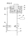
- the hydraulic circuit represented by FIG. 2 comprises an electro-hydraulic distributor 20 which controls the supply of hydraulic liquid to the upper chamber 17 from the supply line 23.
- a pressure regulator 21 the control of which is the arrangement of the operator modifies the pressure of the hydraulic fluid between the supply line 23 located upstream and the line 15 opening into the lower chamber 14.
- a hydraulic damper 19 is connected to the line 15 located downstream of the pressure regulator 21.
- the lower roller 4 Before the engagement of the metal strip between the rollers, the lower roller 4 is in the low and fixed position. This position is obtained by pressurizing the chambers 14 and 17. Because the pressures in these chambers are equal and that the application surface in the chamber 17 is greater than the application surface in the chamber 14, the ring 16 is in abutment against the lower bottom of the cylinder 11. Le. piston 12 is applied against the collar of the ring 16. The position of the upper roller 5 is adjusted by the stops 7.
- the bearings 52 of the upper roller remain applied against the stops 7.
- the rollers 4 and 5 are separated.
- the bearings 42 of the lower roller can then move slightly downwards by pushing the piston 12 and by discharging the liquid from the chamber 14 (or by compressing a fluid in the chamber 14).
- the mobile assembly formed by the lower roller and by its bearings is lighter than the mobile assembly formed by the upper roller and its bearings. As a result, the harmful effects due to the shocks caused by the introduction of the strip are relatively reduced.
- the pressure in the annular chamber 17 is removed using the distributor 20. Therefore the ring 16 is free to move inside the cylinder 17 and it can therefore rise until it comes to abut against the upper bottom - rod side - of the cylinder.
- the stroke of the piston 12 is therefore increased by the stroke of the ring 16.
- the pressurization of the upper chamber 17 corresponds to an intermediate position where the stroke of the piston is limited upwards.
- the elimination of the pressurization of the upper chamber 17 allows the movement of the piston over its entire stroke.
- the lower roller 4 is applied to the metal strip with a force corresponding to the pressure prevailing in the chamber 14. This pres sion is constant but it is adjustable by the operator according to the dimensional characteristics of the strip 2. This adjustment of the pressure in the chamber 14 can be obtained using the pressure regulator 21.
- the pressure can be adjusted differently between the cylinders located on the right and on the left side of the strip so as to compensate for any symmetry defects in the drive device or in the guide of the strip.
- the annular chamber 17 is again pressurized by actuating the distributor 20 so as to return the lower roller to its intermediate or fixed standby position.
Landscapes
- Engineering & Computer Science (AREA)
- Mechanical Engineering (AREA)
- Advancing Webs (AREA)
- Registering, Tensioning, Guiding Webs, And Rollers Therefor (AREA)
- Winding Of Webs (AREA)
Description
- Là présente invention est relative à un dispositif d'entraînement, notamment de bande métallique laminée. Ce dispositif est destiné à être monté à côté d'une enrouleuse de bande dans un laminoir à large bande.
- Dans des dispositifs connus d'entraînement de bande, la bande paase entre deux rouleaux d'entraînement parallèles. montés dans une cage. Le rouleau inférieur - dont le diamètre et le poids sont plue faibles que ceux du rouleau supérieur - est monté fixe dans la cage. Le rouleau supérieur est monté à ses extrémités dans des paliers qui sont guidés verticalement dans la cage et sont manoeuvres par des vérins hydrauliques. 'Le routeau supérieur peut être soulevé lors de l'engagement de la bande de façon à laisser le passage à la bande lorsque celle-ci est dirigée vers une machine située en aval. Le mouvement du rouleau supérieur vers le bas est limité par des butées contre lesquelles les paliers peuvent être appliqués. L'entrefer entre les rouleaux qui est réglé à l'aide des butées est légèrement inférieur à l'épaisseur de la bande laminée lors de l'engagement de la bande. Dans le brevet FR-A-2 281 799 cet entrefer est réglable en fonction de l'épaisseur de la bande laminée par réglage de la position verticale des butées. Dans le brevet FR-A-2 371 976 l'engagement de la bande est favorisé par un vérin pneumatique monté à la suite d'un vérin hydraulique. Toutefois ces dispositifs présentent des inconvénients. Les parties mobiles présentent une Inertie importante lors de l'engagement de la bande laminée et les préréglages ne sont pas faciles à réaliser.
- Dans la cage de laminoir que décrit le certificat d'addition FR-E-85 442, les empoises du cylindre supérieur sont déplacées par des organes moteurs et les empoises du cylindre inférieur reposent sur des tiges de pistons coulissant dans des cylindres de vérins.
- L'invention a pour but de fournir un dispositif d'entraînement de bande laminée pourvu de vérins de manoeuvre du rouleau inférieur dont la construction permet d'amener ledit rouleau à une position intermédiaire éloignée du rouleau supérieur pendant l'attente de l'engagement de la bande. Dans cette position d'attente l'impact d'engagement de la bande peut être amorti. Ce dispositif d'entraînement est pourvu d'un système de déplacement du rouleau supérieur qui assure une course rapide de ce rouleau et qui applique les paliers contre des butées de manière à rattraper une partie des jeux en réalisant une précontrainte. La position de ces butées est réglable en fonction de l'épaisseur de la bande laminée. Le dispositif permet, après engagement de la bande entre les rouleaux entraîneurs, de régler la force de pression sur cette bande, ce réglage pouvant être obtenu séparément sur chaque palier monté à l'extrémité du rouleau inférieur. Il permet d'utiliser une pression hydraulique constante et préréglée, lorsque les rouleaux sont en position d'attente de la bande ou lorsque cette bande est engagée entre ces rouleaux.
- Par rapport au dispositif connu du FR-E-85 442 qui comprend un rouleau supérieur monté à ses extrémités dans des paliers guidés verticalement dans un bâti et des moyens moteurs pour déplacer lesdits paliers et un rouleau inférieur monté à ses extrémités dans des paliers guidés verticalement par le bâti et déplacées chacun par un vérin hydraulique comprenant un cylindre et une tige solidaire d'un piston délimitant une chambre inférieure connectée à un circuit hydraulique, le dispositif selon l'invention est caractérisé par le fait qu'il comporte des butées limitant la course des paliers du rouleau supérieur et que le vérin comporte une bague qui coulisse coté tige dans le cylindre sous l'action de moyens hydrauliques permettant d'amener la bague jusqu'à une position basse où elle limite vers le haut la course du piston à une position intermédiaire de manière que le rouleau inférieur soit écarté du rouleau supérieur avant l'engagement de la bande.
- Selon une caractéristique les moyens hydrauliques associés à la bague sont constitués par une chambre hydraulique formée dans le cylindre au dessus de la bague qui coulisse avec étanchéité dans ledit cylindre et sur la tige laquelle traverse avec étanchéité ledit cylindre, cette chambre étant connectée à une conduite d'alimentation en liquide hydraulique.
- L'invention va maintenant être décrite avec plus de détails en se référant à un mode de réalisation donné à titre d'exemple et représenté par les dessins annexés.
- La figure 1 représente schématiquement en vue latérale et en coupe, le dispositif d'entraînement de bande selon l'invention.
- La figure 2 représente le circuit hydraulique d'un vérin de déplacement du rouleau inférieur du dispositif.
- Le dispositif représenté par la figure 1 sert à entraîner une bande métallique 2 qui vient d'être laminée et qui va être enroulée. Il comprend deux bâtis latéraux 3 qui sont disposés de part et d'autre de la bande métallique 2. Celle-ci passe entre deux rouleaux entraîneurs 4 et 5 dont les axes 41 et 51 sont horizontaux. Des paliers 42 et 52 sont montés respectivement aux extrémités des rouleaux 4 et 5. Ces paliers 42 et 52 sont guidés respectivement par des glissières verticales 31 et 32 formées par des lumières des bâtis latéraux 3. Ainsi les rouleaux 4 et 5 peuvent se déplacer relativement dans un plan vertical. Ces rouleaux entraîneurs 4 et 5 sont entraînés en rotation, autour des axes 41 et 51 respectivement, à l'aide de moyens d'entraînement qui ne sont pas représentés par les dessins.
- Le rouleau supérieur 5 peut être déplacé verticalement à l'aide de moyens moteurs. Ces moyens moteurs sont constitués par des vérins hydrauliques à double effet qui sont associés chacun à un palier 52 du rouleau supérieur. Chacun de ces vérins comprend un cylindre 61 qui est fixé au bâti 3 et un piston 62 qui est solidaire d'une tige 63 articulée à un palier 52 associé. Le rouleau supérieur est en position haute lorsque le dispositif d'enroulement n'est pas utilisé et que la bande est dirigée vers une machine située en aval. Il est en position basse pendant l'utilisation du dispositif d'enroulement. Dans cette position basse, les paliers 52 du rouleau supérieur sont appliqués contre des butées 7 solidaires du bâti 3 et dont la position verticale peut être réglée. Ces butées réglables peuvent être du type à coin ou de type à vérin à vis ou de tout autre type équivalent. Ces butées sont réglées par l'opérateur de telle sorte que l'intervalle entre le rouleau supérieur et le rouleau inférieur soit légèrement inférieur à l'épaisseur de la bande métallique. Les paliers 52 du rouleau supérieur sont appliqués contre les butées 7 avec une force d'application qui est supérieure à l'effort maximal de séparation engendré entre les deux rouleaux d'entraînement de façon à créer une précontrainte des éléments associés à. chaque palier.
- Chaque bâti 3 est équipé d'un vérin hydraulique qui est repéré dans son ensemble par la référence 1. Chacun de ces vérins comprend un cylindre 11 s'appuyant sur le bâti 3 et un piston 12 qui est solidaire d'une tige 13 sur laquelle repose un palier 42 du rouleau inférieur. Le piston délimite, du côté de sa face inférieure et du fond du cylindre, une chambre inférieure 14 qui est alimentée par un conduit 15. La mise en pression de cette chambre 14 déplace verticalement le piston 12 vers le haut. Chaque vérin est équipé de moyens capables de limiter la course du piston vers le haut. A cet effet chaque vérin comprend une bague 16 qui est logée du côté tige dans le cylindre de manière à limiter la course du piston 12 vers le haut. Chaque bague-16 peut coulisser avec étanchéité sur la tige 13 qui traverse elle-même avec étanchéité le cylindre 11. Par ailleurs cette bague 16 peut coulisser avec étanchéité dans l'alésage du cylindre 11 de manière à former une chambre annulaire étanche 17 du côté de sa face supérieure. Cette chambre annulaire 17 qui entoure la tige 13 est connectée à une conduite d'alimentation en liquide hydraulique 18. La bague 16 est susceptible d'être appliquée en position basse contre une butée de manière à définir une position intermédiaire du piston située entre les fins de course de ce piston. Cette butée est constituée par le fond du cylindre 11. La bague 16 a une forme en cloche qui lui permet de venir buter contre le fond du cylindre 11 lorsque la chambre 17 est mise en pression. Du fait de la forme en cloche de la bague 16, le diamètre du piston 12 est inférieur au diamètre de l'alésage intérieur du cylindre 11. Le piston 12 est libre de se déplacer à l'intérieur de la bague 16 dont la collerette supérieure peut s'appliquer contre l'épaulement formé par le pîston et sa tige. Le diamètre de la chambre inférieure 14 est de préférence inférieur au diamètre du piston 12. La surface annulaire d'application de la pression sur la bague, du côté de la chambre annulaire 17, est supérieure à la surface d'application de la pression sur la face inférieure du piston, du côté de la chambre 14. De ce fait, lorsque les chambres 17 et 14 sont alimentées sous des pressions égales, la bague 16 est appliquée contre le fond inférieur du cylindre 11.
- Le circuit hydraulique représenté par la figure 2 comporte un distributeur électrohydrau- lique 20 qui contrôle l'alimentation en liquide hydraulique de la chambre supérieure 17 à partir de la conduite d'alimentation 23. Un régulateur de pression 21 dont la commande est la disposition de l'opérateur modifie la pression du liquide hydraulique entre la conduite d'alimentation 23 située en amont et la conduite 15 débouchant dans la chambre inférieure 14. Un amortisseur hydraulique 19 est branché sur la conduite 15 située en aval du régulateur de pression 21.
- Le fonctionnement du dispositif d'entraînement va maintenant être expliqué en se référant aux figures 1 et 2.
- Avant l'engagement de la bande métallique entre les rouleaux, le rouleau inférieur 4 se trouve en position basse et fixe. Cette position est obtenue en mettant sous pression les chambres 14 et 17. Du fait que les pressions dans ces chambres sont égales et que la surface d'application dans la chambre 17 est supérieure à la surface d'application dans la chambre 14, la bague 16 se trouve en butée contre le fond inférieur du cylindre 11. Le. piston 12 est appliqué contre la collerette de la bague 16. La position du rouleau supérieur 5 est réglée par les butées 7.
- Lors de l'engagement de la bande métallique entre les rouleaux, les paliers 52 du rouleau supérieur restent appliqués contre les butées 7. Les rouleaux 4 et 5 sont écartés. Les paliers 42 du rouleau inférieur peuvent alors se déplacer légèrement vers le bas en repoussant le piston 12 et en refoulant le liquide de la chambre 14 (ou en comprimant un fluide dans la chambre 14). L'ensemble mobile formé par le rouleau inférieur et par ses paliers est plus léger que l'ensemble mobile formé par le rouleau supérieur et ses paliers. De ce fait, les effets néfastes dûs aux chocs causés par l'introduction de la bande sont relativement réduits.
- Dès que la bande métallique s'est introduite entre les rouleaux entraîneurs, la pression dans la chambre annulaire 17 est supprimée à l'aide du distributeur 20. De ce fait la bague 16 est libre de se déplacer à l'intérieur du cylindre 17 et elle peut donc monter jusqu'à venir buter contre le fond supérieur - côté tige - du cylindre. La course du piston 12 est donc augmentée de la course de la bague 16. La mise en pression de la chambre supérieure 17 correspond à une position intermédiaire où la course du piston est limitée vers le haut. Au contraire la suppression de la mise en pression de la chambre supérieure 17 permet le mouvement du piston sur toute sa course. Le rouleau inférieur 4 est appliqué sur la bande métallique avec une force correspondant à la pression régnant dans la chambre 14. Cette pression est constante mais elle est réglable par l'opérateur en fonction des caractéristiques dimensionnelles de la bande 2. Ce réglage de la pression dans la chambre 14 peut être obtenu à l'aide du régulateur de pression 21. La pression peut être réglée différemment entre les vérins situés du côté droit et du côté gauche de la bande de façon à compenser les défauts de symétrie éventuels dans le dispositif d'entraînement ou dans le guidage de la bande.
- Lorsque la fin de la bande métallique 2 quitte les rouleaux entraîneurs, la chambre annulaire 17 est de nouveau mise sous pression par manceu- vre du distributeur 20 de manière à ramener le rouleau inférieur dans sa position intermédiaire ou d'attente fixe.
Claims (6)
Applications Claiming Priority (2)
| Application Number | Priority Date | Filing Date | Title |
|---|---|---|---|
| FR7916350 | 1979-06-26 | ||
| FR7916350A FR2459692A1 (fr) | 1979-06-26 | 1979-06-26 | Dispositif d'entrainement de bande |
Publications (2)
| Publication Number | Publication Date |
|---|---|
| EP0021995A1 EP0021995A1 (fr) | 1981-01-07 |
| EP0021995B1 true EP0021995B1 (fr) | 1983-07-13 |
Family
ID=9227087
Family Applications (1)
| Application Number | Title | Priority Date | Filing Date |
|---|---|---|---|
| EP19800400899 Expired EP0021995B1 (fr) | 1979-06-26 | 1980-06-18 | Dispositif d'entrainement de bande |
Country Status (4)
| Country | Link |
|---|---|
| EP (1) | EP0021995B1 (fr) |
| DE (1) | DE3064116D1 (fr) |
| ES (1) | ES492749A0 (fr) |
| FR (1) | FR2459692A1 (fr) |
Families Citing this family (7)
| Publication number | Priority date | Publication date | Assignee | Title |
|---|---|---|---|---|
| DE3507251A1 (de) * | 1985-03-01 | 1986-09-04 | SMS Schloemann-Siemag AG, 4000 Düsseldorf | Treibapparat fuer walzband |
| DE3529720A1 (de) * | 1985-08-20 | 1987-03-05 | Mannesmann Ag | Anordnung eines hydraulischen anstellzylinders |
| DE59504983D1 (de) * | 1995-01-16 | 1999-03-11 | Mannesmann Ag | Vorrichtung zum Führen von warmgewalztem Band durch einen Induktor |
| FR2820061B1 (fr) * | 2001-01-30 | 2003-05-02 | Vai Clecim | Dispositif d'entrainement et de guidage d'une bande |
| CN101733286B (zh) * | 2008-11-04 | 2012-10-03 | 上海重型机器厂有限公司 | 用于调整中厚板轧机轧制线标高的装置及其调整方法 |
| CN115532912B (zh) * | 2022-10-24 | 2026-04-14 | 南通超力卷板机制造有限公司 | 一种金属材料滚弯成形不等厚避让装置及避让方法 |
| CN117282899B (zh) * | 2023-11-27 | 2024-02-02 | 山西恒冠重工集团有限公司 | 一种法兰加工用锻压装置 |
Family Cites Families (6)
| Publication number | Priority date | Publication date | Assignee | Title |
|---|---|---|---|---|
| US2796781A (en) * | 1953-11-09 | 1957-06-25 | Aetna Standard Eng Co | Roll adjusting mechanism |
| FR85442E (fr) * | 1960-03-14 | 1965-08-06 | Moeller & Neumann Verwalt Ges | Dispositif hydraulique de mise à poste pour laminoirs |
| FR1539009A (fr) * | 1967-05-22 | 1968-09-13 | Spidem Ste Nle | Perfectionnement aux vérins et applications |
| US3645120A (en) * | 1970-02-19 | 1972-02-29 | Gulf & Western Ind Prod Co | Coiling apparatus |
| NL177287C (nl) * | 1974-08-13 | 1985-09-02 | Hoesch Werke Ag | Aandrijfinrichting voor bandvormig walsgoed. |
| DE2653725C2 (de) * | 1976-11-26 | 1983-03-17 | SMS Schloemann-Siemag AG, 4000 Düsseldorf | Zweirollen-Treibvorrichtung für Bandhaspel |
-
1979
- 1979-06-26 FR FR7916350A patent/FR2459692A1/fr active Granted
-
1980
- 1980-06-18 DE DE8080400899T patent/DE3064116D1/de not_active Expired
- 1980-06-18 EP EP19800400899 patent/EP0021995B1/fr not_active Expired
- 1980-06-25 ES ES492749A patent/ES492749A0/es active Granted
Also Published As
| Publication number | Publication date |
|---|---|
| ES8102859A1 (es) | 1981-02-16 |
| FR2459692B1 (fr) | 1982-09-24 |
| FR2459692A1 (fr) | 1981-01-16 |
| DE3064116D1 (en) | 1983-08-18 |
| ES492749A0 (es) | 1981-02-16 |
| EP0021995A1 (fr) | 1981-01-07 |
Similar Documents
| Publication | Publication Date | Title |
|---|---|---|
| EP0006076B1 (fr) | Elévateur à cabine autonome pour grimper le long d'un mât | |
| EP3556634B1 (fr) | Véhicule ferroviaire et procédé de circulation associé | |
| FR2729936A1 (fr) | Systeme de securite pour dispositif de separation des charges dans un couloir de stockage dynamique | |
| EP0292413B1 (fr) | Dispositif compensateur de charge pour un engin de manutention et procédé pour la mise en oeuvre d'une telle compensation | |
| EP0161119A1 (fr) | Mécanisme d'actionnement de frein à disque | |
| EP1110857B1 (fr) | Dispositif d'équilibrage d'un navire, notamment en roulis | |
| EP0021995A1 (fr) | Dispositif d'entrainement de bande | |
| EP3254924A1 (fr) | Véhicule ferroviaire pourvu d'un nivellement et procédé de circulation associé | |
| CH332160A (fr) | Mécanisme amortisseur de chocs du chariot mobile d'une machine de bureau | |
| EP0564345B1 (fr) | Dispositif de sertissage de boîtes de conserve à grande cadence | |
| FR2564052A1 (fr) | Ralentisseur de wagon de chemin de fer | |
| BE488601A (fr) | ||
| FR2670696A1 (fr) | Machine a dessabler. | |
| EP1226886B1 (fr) | Dispositif d'entrainement et de guidage d'une bande | |
| EP0133399B1 (fr) | Dispositif de sécurité hydraulique pour mécanisme de serrage des cylindres de laminoir | |
| US4255829A (en) | Installation for removal of surplus material from a block of cellular concrete | |
| BE1012724A3 (fr) | Moteur lineaire pneumatique pour vanne de commande cryogenique. | |
| EP0001363A1 (fr) | Dispositif d'obturation de l'extrémité d'une conduite de remplissage de citerne | |
| FR2539178A1 (fr) | Porte a commande par chaine a double securite | |
| FR2471299A1 (fr) | Ensemble de prise de courant a deperchage et reperchage automatiques, pour vehicules a traction electrique, notamment les trolleybus | |
| CA1326246C (fr) | Dispositif de serrage de cadres | |
| CH576388A5 (en) | Ramp for loading and unloading vehicles - is counterbalanced using closed circuit hydraulic rams with balancing pressure exerted by springs | |
| EP0044785B1 (fr) | Presse pneumatique pour le bombage de feuilles de verre | |
| CH335499A (fr) | Robinet de commande pour installation de freinage à fluide sous pression | |
| CH361953A (fr) | Dispositif d'avancement automatique pas à pas d'un élément allongé dans une machine |
Legal Events
| Date | Code | Title | Description |
|---|---|---|---|
| PUAI | Public reference made under article 153(3) epc to a published international application that has entered the european phase |
Free format text: ORIGINAL CODE: 0009012 |
|
| AK | Designated contracting states |
Designated state(s): BE DE NL |
|
| 17P | Request for examination filed |
Effective date: 19801126 |
|
| GRAA | (expected) grant |
Free format text: ORIGINAL CODE: 0009210 |
|
| AK | Designated contracting states |
Designated state(s): BE DE NL |
|
| REF | Corresponds to: |
Ref document number: 3064116 Country of ref document: DE Date of ref document: 19830818 |
|
| PLBE | No opposition filed within time limit |
Free format text: ORIGINAL CODE: 0009261 |
|
| STAA | Information on the status of an ep patent application or granted ep patent |
Free format text: STATUS: NO OPPOSITION FILED WITHIN TIME LIMIT |
|
| PGFP | Annual fee paid to national office [announced via postgrant information from national office to epo] |
Ref country code: BE Payment date: 19840630 Year of fee payment: 5 |
|
| 26N | No opposition filed | ||
| PGFP | Annual fee paid to national office [announced via postgrant information from national office to epo] |
Ref country code: DE Payment date: 19840808 Year of fee payment: 5 |
|
| PGFP | Annual fee paid to national office [announced via postgrant information from national office to epo] |
Ref country code: NL Payment date: 19850630 Year of fee payment: 6 |
|
| PG25 | Lapsed in a contracting state [announced via postgrant information from national office to epo] |
Ref country code: BE Effective date: 19860630 |
|
| BERE | Be: lapsed |
Owner name: SECIM Effective date: 19860630 |
|
| PG25 | Lapsed in a contracting state [announced via postgrant information from national office to epo] |
Ref country code: NL Effective date: 19870101 |
|
| NLV4 | Nl: lapsed or anulled due to non-payment of the annual fee | ||
| PG25 | Lapsed in a contracting state [announced via postgrant information from national office to epo] |
Ref country code: DE Effective date: 19870303 |