EP0021888B1 - Moniteur de station de maintenance, et station de maintenance le comportant - Google Patents
Moniteur de station de maintenance, et station de maintenance le comportant Download PDFInfo
- Publication number
- EP0021888B1 EP0021888B1 EP80400747A EP80400747A EP0021888B1 EP 0021888 B1 EP0021888 B1 EP 0021888B1 EP 80400747 A EP80400747 A EP 80400747A EP 80400747 A EP80400747 A EP 80400747A EP 0021888 B1 EP0021888 B1 EP 0021888B1
- Authority
- EP
- European Patent Office
- Prior art keywords
- maintenance
- procedure
- monitor
- recorded
- maintenance station
- Prior art date
- Legal status (The legal status is an assumption and is not a legal conclusion. Google has not performed a legal analysis and makes no representation as to the accuracy of the status listed.)
- Expired
Links
- 238000012423 maintenance Methods 0.000 title claims description 56
- 238000000034 method Methods 0.000 claims description 37
- 238000012800 visualization Methods 0.000 claims description 6
- 230000001360 synchronised effect Effects 0.000 claims 1
- 238000012360 testing method Methods 0.000 description 9
- 238000010586 diagram Methods 0.000 description 8
- 230000002950 deficient Effects 0.000 description 4
- 210000000056 organ Anatomy 0.000 description 3
- 230000006978 adaptation Effects 0.000 description 2
- 230000007547 defect Effects 0.000 description 2
- 230000006870 function Effects 0.000 description 2
- 238000005259 measurement Methods 0.000 description 2
- 238000012544 monitoring process Methods 0.000 description 2
- 238000010998 test method Methods 0.000 description 2
- 238000011161 development Methods 0.000 description 1
- 238000002405 diagnostic procedure Methods 0.000 description 1
- 238000012144 step-by-step procedure Methods 0.000 description 1
- 230000000007 visual effect Effects 0.000 description 1
Images

Classifications
-
- G—PHYSICS
- G05—CONTROLLING; REGULATING
- G05B—CONTROL OR REGULATING SYSTEMS IN GENERAL; FUNCTIONAL ELEMENTS OF SUCH SYSTEMS; MONITORING OR TESTING ARRANGEMENTS FOR SUCH SYSTEMS OR ELEMENTS
- G05B19/00—Programme-control systems
- G05B19/02—Programme-control systems electric
- G05B19/04—Programme control other than numerical control, i.e. in sequence controllers or logic controllers
- G05B19/042—Programme control other than numerical control, i.e. in sequence controllers or logic controllers using digital processors
-
- G—PHYSICS
- G05—CONTROLLING; REGULATING
- G05B—CONTROL OR REGULATING SYSTEMS IN GENERAL; FUNCTIONAL ELEMENTS OF SUCH SYSTEMS; MONITORING OR TESTING ARRANGEMENTS FOR SUCH SYSTEMS OR ELEMENTS
- G05B2219/00—Program-control systems
- G05B2219/20—Pc systems
- G05B2219/24—Pc safety
- G05B2219/24019—Computer assisted maintenance
Definitions
- the present invention relates to a maintenance station monitor.
- maintenance station monitor is meant an apparatus intended to assist a technician assigned to a test station, for monitoring performance and / or locating faults in an electronic, electromechanical and / or hydraulic sub-assembly.
- Any electronic, electromechanical or hydraulic system or equipment poses maintenance problems, a word covering a fairly large number of operations that must be carried out on such a system or equipment, to verify its performance and operation by identifying defective organs or the points of these bodies where certain defects appear and possibly provide a remedy to the failures noted.
- the purpose of direct maintenance is to allow a user to maintain the supported system in operational condition on the site where it is located.
- This maintenance has for this purpose, test means which allow it to diagnose a failure of a system and to provide a remedy by a standard exchange in general at the level of a sub-assembly.
- Industrial type maintenance often complements direct maintenance; a defective item having been isolated on site, it is generally sent to a repair center, which is in most cases the factory where it was manufactured, in order to be repaired there.
- An automatic bench consists of a computer controlling a suitable instrumentation bay.
- Such a bench offers the advantage of using only relatively unskilled personnel for its operation, but its maintenance and the preparation of programs can only be carried out by specialists.
- it has the disadvantage for a user of having been designed to ensure the control of large series of subassemblies deemed good and is therefore poorly suited to the search for faults on defective devices from the sites.
- a manual bench often made up of specific instruments, is generally designed for the control of a particular function and is used by specialists familiar with the equipment they have to control.
- its structure, as for the automatic bench, is adapted to high rates.
- the object of the invention is to define an apparatus called a maintenance station monitor which is designed and produced to assist a user in solving industrial maintenance problems himself, without being hampered by the advantages attached to the maintenance devices of this type currently used, which are in fact disadvantages for him, mainly as a result of poor adaptation to the treatment of a small number of devices, the need to call in specialists, development of complex programs in particular language.
- a maintenance station monitor comprising a logic control unit controlling the maintenance procedure of an electronic, electromechanical and / or hydraulic system from data recorded on a hardware medium , including means of acquiring data concerning the maintenance procedure recorded on the hardware medium, means of presenting this procedure, connected at the output of the control unit, means of intervention by an operator in the process of the procedure and interface means connecting the monitor with at least one instrumentation bay
- the support introduced into the reading device of the acquisition means is a flexible disk in which the text is recorded in plain text a maintenance procedure and in coded form the instructions for ordering an instrumentation bay connected to the monitor and / or device ls programmable from a system subject to maintenance and that the display console belonging to the presentation means clearly displays instructions concerning the step-by-step procedure of the maintenance procedure and that the presentation means include in addition a programmable microfiche projector ensuring under the control of the instructions carried on the flexible disc the visualization of views and / or diagrams whose images are recorded on a support independent of the
- a maintenance monitor has a number of advantages under these conditions. It is first of all capable of controlling any maintenance station, electronic, electromechanical or hydraulic, thanks to the always possible establishment of a complete file of procedures constituting the mass memory of the logic unit and the establishment in this context in clear without using any code; under these conditions the monitor is capable of self-monitoring.
- the presentation means allowing, among other things, the visualization of the procedure, provide a powerful aid to the operator who "sees" the test taking place before his eyes and who, having means of intervention, can act on the progress of the procedure , whereas, according to the prior art, the tests are generally carried out automatically, the intervention of the operator practically never taking place, except sometimes when the test is controlled by a powerful computer.
- the monitor since the systems subject to maintenance require an appropriate instrumentation bay, the monitor has standardized interfaces capable of connecting to any instrumentation bay.
- the maintenance station monitor object of the present invention is in the form of a relatively simple device, which can be portable, capable of piloting, semi-automatically, maintenance stations available to a user who can intervene, if necessary, in the course of the procedure, and whose intervention is facilitated by the visual presentation of the maintenance procedure.
- FIG. 1 represents the functional block diagram of a maintenance station monitor according to the invention. It comprises a logic control unit 1, in the form of a microcomputer or a microprocessor, connected to a data acquisition device 2, or mass memory, of the presentation means 3, connected at the output of the logic unit 1 and interface means 4, allowing the connection of the logic unit to one or more instrumentation bays 5, themselves connected to the systems subject to the maintenance procedure.
- 6 shows the means available to an operator, generally a control console connected to the logic unit 1.
- the link 7 in broken lines between the presentation means 3 and the console 6, indicates the intervention possible and often requested from the operator.
- FIG. 2 gives a more detailed representation of the block diagram of the monitor according to the invention.
- the logic control unit 1 around which the monitor is built, comprises a central unit 8 with a clock 9 and a central memory 10 comprising a read-only memory 11 which can constitute the software and a random access memory or buffer memory 12.
- Buses interconnection 13 connect the various components of the logic control unit 1, to the various essential means which have been set out in the description of FIG. 1 and to other auxiliary means, through adaptation couplers grouped under the reference 14.
- the so-called data acquisition means 2 consist, in a first version of the monitor according to the invention, of a flexible disc player 15 and the presentation means 3 then consist of a display console and a microfiche projector 17, of which the use is advantageously adapted to the fact that the monitor is capable of connecting to any measurement bay and that the operations are very frequent.
- the interconnection bus 13 connects, as has been said, to the control logic unit 1, interface means 4 comprising for example three interfaces 19, 20 and 21, it being understood that this number is not limiting .
- the reference 5 denotes the instrumentation bays themselves connected to the systems whose maintenance is being carried out.
- the data acquisition means consist of a video disc on which all the procedure data are recorded, text, specific instructions, diagrams, figures.
- the presentation means are unique, constituted for example by a cathode ray tube, possibly in color.
- the means. data acquisition 2 are constituted by a flexible disk drive in a first version.
- the maintenance procedure in the form of a plain text, indicating inter alia the elementary tasks that the operator will have to perform during the course of the procedure and coded instructions intended for the control of the measuring devices of the instrumentation bays connected to the monitor, or of programmable devices of the systems subject to maintenance.
- the display console 16 which in the first example perhaps describes a plasma gas screen, presents, step by step, the text of the procedure, as it is recorded on the flexible disk.
- the operation of the monitor comprising a video disc does not differ significantly from that which has just been exposed. Simply there is only one presentation device, a cathode ray tube, instead of two devices.
- each instruction appears sequentially on the display screen and the operator can, therefore, perform the measurements requested from him on the measuring devices; he can assess whether the results are good or bad and can then call a new instruction.
- the operator being able and in certain cases having to intervene during the course of the procedure, he has a numerical keyboard 6 allowing him for example to call any part of the procedure which he wishes to consult.
- the keyboard includes, of course, the on-off control of the monitor and that of its self-control. It also includes a control of a printer 18 provided for automatically obtaining the reference of any test.
- the monitor according to the invention adaptable as has already been said to any kind of test equipment, has a number of interfaces giving it a considerable flexibility of use.
- the monitor can be equipped with at least 5 interface cards of three different types, 3 of these interfaces being referenced 19, 20, 21 in FIG. 2.
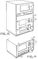
- FIG. 3 presents a schematic view of the monitor showing the arrangement of the means which it comprises, grouped on the front face 22 of the device. From the top to the bottom, we recognize the programmable microfiche projector 17 giving explanatory views of the test procedure, a device 23 for controlling the microfiche projector, with a slot 24 for introducing the microfiche, the control console 6, the alphanumeric plasma display console 16 which gives the plain text of the test procedure, the printer 18 which gives the reference of the tests mainly those whose results are incorrect and the flexible disc player 15.
- Figure 4 presents a schematic view similar to that of Figure 3, for the second version of the monitor using a video disc.
- On the front face 22 of the monitor appear only the cathode ray tube, of presentation 3 grouping the functions of the display console 16 of FIG. 3 and the microfiche projector, the video disc player 25, the keyboard 6 and printer 18.
Landscapes
- Physics & Mathematics (AREA)
- General Physics & Mathematics (AREA)
- Engineering & Computer Science (AREA)
- Automation & Control Theory (AREA)
- Testing And Monitoring For Control Systems (AREA)
Applications Claiming Priority (2)
| Application Number | Priority Date | Filing Date | Title |
|---|---|---|---|
| FR7914721 | 1979-06-08 | ||
| FR7914721A FR2458850A1 (fr) | 1979-06-08 | 1979-06-08 | Moniteur de station de maintenance et station de maintenance le comprenant |
Publications (2)
| Publication Number | Publication Date |
|---|---|
| EP0021888A1 EP0021888A1 (fr) | 1981-01-07 |
| EP0021888B1 true EP0021888B1 (fr) | 1983-10-12 |
Family
ID=9226381
Family Applications (1)
| Application Number | Title | Priority Date | Filing Date |
|---|---|---|---|
| EP80400747A Expired EP0021888B1 (fr) | 1979-06-08 | 1980-05-28 | Moniteur de station de maintenance, et station de maintenance le comportant |
Country Status (3)
| Country | Link |
|---|---|
| EP (1) | EP0021888B1 (enExample) |
| DE (1) | DE3065262D1 (enExample) |
| FR (1) | FR2458850A1 (enExample) |
Families Citing this family (5)
| Publication number | Priority date | Publication date | Assignee | Title |
|---|---|---|---|---|
| DE3215301A1 (de) * | 1982-04-21 | 1983-10-27 | Siemens AG, 1000 Berlin und 8000 München | Foerderanlage mit sende- und empfangsstation, die jeweils individuelle steuersaetze aufweisen, die ueber einen datenbus an eine zentrale programmsteuereinrichtung angeschlossen sind |
| FR2526185A1 (fr) * | 1982-05-03 | 1983-11-04 | Lertie Sa | Procede et appareil de controle de surete de fonctionnement et d'identification de programmes |
| FR2531230A1 (fr) * | 1982-07-27 | 1984-02-03 | Rank Xerox Sa | Ensemble destine au test automatique centralise de circuits imprimes et procede de test de circuits a microprocesseur faisant application de cet ensemble |
| FR2689359B1 (fr) * | 1992-03-27 | 1996-06-14 | Aerospatiale | Dispositif d'aide a la maintenance pour torche a plasma. |
| US6021667A (en) * | 1998-10-01 | 2000-02-08 | Dowty Aerospace Yakima | Automated work station apparatus and method |
Family Cites Families (1)
| Publication number | Priority date | Publication date | Assignee | Title |
|---|---|---|---|---|
| US3992092A (en) * | 1975-02-21 | 1976-11-16 | International Telephone And Telegraph Corporation | Microfilm instruction system |
-
1979
- 1979-06-08 FR FR7914721A patent/FR2458850A1/fr active Granted
-
1980
- 1980-05-28 DE DE8080400747T patent/DE3065262D1/de not_active Expired
- 1980-05-28 EP EP80400747A patent/EP0021888B1/fr not_active Expired
Non-Patent Citations (3)
| Title |
|---|
| ELEKTRONIK. Bd. 23. Heft 2. 1974, Ing. Otto Limann. pp. 64-66 * |
| FELTRON, Microcomputer-Information Gruppe 3.7.1.2/Hewlett-Packard 15.5.1978. * |
| FELTRON, Microcomputer-Information Gruppe 3.7.1-6/Texas Instruments 15.1.1978 * |
Also Published As
| Publication number | Publication date |
|---|---|
| FR2458850B1 (enExample) | 1984-07-06 |
| FR2458850A1 (fr) | 1981-01-02 |
| EP0021888A1 (fr) | 1981-01-07 |
| DE3065262D1 (en) | 1983-11-17 |
Similar Documents
| Publication | Publication Date | Title |
|---|---|---|
| Fisher et al. | Hypermedia image processing reference | |
| US4654852A (en) | On-line problem-determination procedure for diagnosis of faults in a data-processing system | |
| EP1402716B1 (en) | System and method for removing sensitive data from diagnostic images | |
| JP2014002320A (ja) | 内視鏡装置、内視鏡画像記録用フォルダ生成方法及びプログラム | |
| US4954964A (en) | Apparatus and method for expert analysis of metal failure with automated visual aide | |
| FR2541474A1 (fr) | Entretien d'un ascenseur commande par logiciel | |
| EP0997638A3 (en) | System for dynamic diagnosis of apparatus operating conditions | |
| KR100751160B1 (ko) | 의료용 화상 기록 시스템 | |
| EP0021888B1 (fr) | Moniteur de station de maintenance, et station de maintenance le comportant | |
| WO2020054422A1 (ja) | 端末装置、作業機械システム、情報処理方法、およびサーバ装置 | |
| FR3086406A1 (fr) | Banc de test automatise, non intrusif, destine a realiser des tests mecaniques et/ou logiciels et/ou visuels et/ou sonores d’interface homme-machine d’un appareil/equipement | |
| EP0053561A2 (fr) | Testeur spécifique modulaire, automatisé et portable | |
| FR2473766A1 (fr) | Dispositif d'affichage de blocs de sequences | |
| JPH04260178A (ja) | 画像処理装置用検査装置及びその検査方法 | |
| CA1256498A (fr) | Appareil universel de detection de defectuosites dans des systemes a microprocesseur | |
| US20140237431A1 (en) | Endoscope image management apparatus and endoscope image display method | |
| JP2002022503A (ja) | 測定システム、測定器、表示方法、および表示プログラムを記録した記録媒体 | |
| JP6242075B2 (ja) | 内視鏡装置及び内視鏡画像記録用フォルダの表示方法 | |
| KR20020065143A (ko) | Pc 장애 자동 진단과 복구 방법 및 그 장치 | |
| JP2008065555A (ja) | 画像処理装置の機能診断方法及び機能診断システム | |
| JP7768802B2 (ja) | 検査画像表示方法、検査支援装置、検査支援システム、およびプログラム | |
| JPH08272932A (ja) | 画像ファイル装置 | |
| EP4529829A1 (en) | Portable modular system for diagnostic instruments | |
| FR2717902A1 (fr) | Procédé et dispositif d'élaboration de tests de cartes électroniques. | |
| BE1005188A6 (fr) | Procedures pour assurer la securite des donnees. |
Legal Events
| Date | Code | Title | Description |
|---|---|---|---|
| PUAI | Public reference made under article 153(3) epc to a published international application that has entered the european phase |
Free format text: ORIGINAL CODE: 0009012 |
|
| AK | Designated contracting states |
Designated state(s): BE CH DE GB IT LI NL SE |
|
| 17P | Request for examination filed |
Effective date: 19810121 |
|
| ITF | It: translation for a ep patent filed | ||
| GRAA | (expected) grant |
Free format text: ORIGINAL CODE: 0009210 |
|
| AK | Designated contracting states |
Designated state(s): BE CH DE GB IT LI NL SE |
|
| REF | Corresponds to: |
Ref document number: 3065262 Country of ref document: DE Date of ref document: 19831117 |
|
| PGFP | Annual fee paid to national office [announced via postgrant information from national office to epo] |
Ref country code: DE Payment date: 19840402 Year of fee payment: 5 |
|
| PGFP | Annual fee paid to national office [announced via postgrant information from national office to epo] |
Ref country code: CH Payment date: 19840424 Year of fee payment: 5 |
|
| PGFP | Annual fee paid to national office [announced via postgrant information from national office to epo] |
Ref country code: SE Payment date: 19840630 Year of fee payment: 5 Ref country code: BE Payment date: 19840630 Year of fee payment: 5 |
|
| PLBE | No opposition filed within time limit |
Free format text: ORIGINAL CODE: 0009261 |
|
| STAA | Information on the status of an ep patent application or granted ep patent |
Free format text: STATUS: NO OPPOSITION FILED WITHIN TIME LIMIT |
|
| 26N | No opposition filed | ||
| PGFP | Annual fee paid to national office [announced via postgrant information from national office to epo] |
Ref country code: NL Payment date: 19850531 Year of fee payment: 6 |
|
| PG25 | Lapsed in a contracting state [announced via postgrant information from national office to epo] |
Ref country code: SE Effective date: 19860529 |
|
| PG25 | Lapsed in a contracting state [announced via postgrant information from national office to epo] |
Ref country code: LI Effective date: 19860531 Ref country code: CH Effective date: 19860531 Ref country code: BE Effective date: 19860531 |
|
| BERE | Be: lapsed |
Owner name: THOMSON-CSF Effective date: 19860531 |
|
| PG25 | Lapsed in a contracting state [announced via postgrant information from national office to epo] |
Ref country code: NL Effective date: 19861201 |
|
| NLV4 | Nl: lapsed or anulled due to non-payment of the annual fee | ||
| GBPC | Gb: european patent ceased through non-payment of renewal fee | ||
| REG | Reference to a national code |
Ref country code: CH Ref legal event code: PL |
|
| PG25 | Lapsed in a contracting state [announced via postgrant information from national office to epo] |
Ref country code: DE Effective date: 19870203 |
|
| PG25 | Lapsed in a contracting state [announced via postgrant information from national office to epo] |
Ref country code: GB Effective date: 19881118 |
|
| EUG | Se: european patent has lapsed |
Ref document number: 80400747.4 Effective date: 19870225 |