EP0020915B1 - Verfahren zum nahtlosen Verbinden von thermoplastischen Kunststoffhohlprofilen und Vorrichtung zur Durchführung des Verfahrens - Google Patents
Verfahren zum nahtlosen Verbinden von thermoplastischen Kunststoffhohlprofilen und Vorrichtung zur Durchführung des Verfahrens Download PDFInfo
- Publication number
- EP0020915B1 EP0020915B1 EP80102097A EP80102097A EP0020915B1 EP 0020915 B1 EP0020915 B1 EP 0020915B1 EP 80102097 A EP80102097 A EP 80102097A EP 80102097 A EP80102097 A EP 80102097A EP 0020915 B1 EP0020915 B1 EP 0020915B1
- Authority
- EP
- European Patent Office
- Prior art keywords
- profiles
- hollow
- outer mould
- hollow profiles
- supporting device
- Prior art date
- Legal status (The legal status is an assumption and is not a legal conclusion. Google has not performed a legal analysis and makes no representation as to the accuracy of the status listed.)
- Expired
Links
Images
Classifications
-
- B—PERFORMING OPERATIONS; TRANSPORTING
- B29—WORKING OF PLASTICS; WORKING OF SUBSTANCES IN A PLASTIC STATE IN GENERAL
- B29C—SHAPING OR JOINING OF PLASTICS; SHAPING OF MATERIAL IN A PLASTIC STATE, NOT OTHERWISE PROVIDED FOR; AFTER-TREATMENT OF THE SHAPED PRODUCTS, e.g. REPAIRING
- B29C65/00—Joining or sealing of preformed parts, e.g. welding of plastics materials; Apparatus therefor
- B29C65/02—Joining or sealing of preformed parts, e.g. welding of plastics materials; Apparatus therefor by heating, with or without pressure
- B29C65/18—Joining or sealing of preformed parts, e.g. welding of plastics materials; Apparatus therefor by heating, with or without pressure using heated tools
-
- B—PERFORMING OPERATIONS; TRANSPORTING
- B29—WORKING OF PLASTICS; WORKING OF SUBSTANCES IN A PLASTIC STATE IN GENERAL
- B29C—SHAPING OR JOINING OF PLASTICS; SHAPING OF MATERIAL IN A PLASTIC STATE, NOT OTHERWISE PROVIDED FOR; AFTER-TREATMENT OF THE SHAPED PRODUCTS, e.g. REPAIRING
- B29C66/00—General aspects of processes or apparatus for joining preformed parts
- B29C66/01—General aspects dealing with the joint area or with the area to be joined
- B29C66/05—Particular design of joint configurations
- B29C66/10—Particular design of joint configurations particular design of the joint cross-sections
- B29C66/11—Joint cross-sections comprising a single joint-segment, i.e. one of the parts to be joined comprising a single joint-segment in the joint cross-section
- B29C66/114—Single butt joints
- B29C66/1142—Single butt to butt joints
-
- B—PERFORMING OPERATIONS; TRANSPORTING
- B29—WORKING OF PLASTICS; WORKING OF SUBSTANCES IN A PLASTIC STATE IN GENERAL
- B29C—SHAPING OR JOINING OF PLASTICS; SHAPING OF MATERIAL IN A PLASTIC STATE, NOT OTHERWISE PROVIDED FOR; AFTER-TREATMENT OF THE SHAPED PRODUCTS, e.g. REPAIRING
- B29C66/00—General aspects of processes or apparatus for joining preformed parts
- B29C66/01—General aspects dealing with the joint area or with the area to be joined
- B29C66/32—Measures for keeping the burr form under control; Avoiding burr formation; Shaping the burr
- B29C66/324—Avoiding burr formation
- B29C66/3242—Avoiding burr formation on the inside of a tubular or hollow article
-
- B—PERFORMING OPERATIONS; TRANSPORTING
- B29—WORKING OF PLASTICS; WORKING OF SUBSTANCES IN A PLASTIC STATE IN GENERAL
- B29C—SHAPING OR JOINING OF PLASTICS; SHAPING OF MATERIAL IN A PLASTIC STATE, NOT OTHERWISE PROVIDED FOR; AFTER-TREATMENT OF THE SHAPED PRODUCTS, e.g. REPAIRING
- B29C66/00—General aspects of processes or apparatus for joining preformed parts
- B29C66/01—General aspects dealing with the joint area or with the area to be joined
- B29C66/348—Avoiding melting or weakening of the zone directly next to the joint area, e.g. by cooling
-
- B—PERFORMING OPERATIONS; TRANSPORTING
- B29—WORKING OF PLASTICS; WORKING OF SUBSTANCES IN A PLASTIC STATE IN GENERAL
- B29C—SHAPING OR JOINING OF PLASTICS; SHAPING OF MATERIAL IN A PLASTIC STATE, NOT OTHERWISE PROVIDED FOR; AFTER-TREATMENT OF THE SHAPED PRODUCTS, e.g. REPAIRING
- B29C66/00—General aspects of processes or apparatus for joining preformed parts
- B29C66/50—General aspects of joining tubular articles; General aspects of joining long products, i.e. bars or profiled elements; General aspects of joining single elements to tubular articles, hollow articles or bars; General aspects of joining several hollow-preforms to form hollow or tubular articles
- B29C66/51—Joining tubular articles, profiled elements or bars; Joining single elements to tubular articles, hollow articles or bars; Joining several hollow-preforms to form hollow or tubular articles
- B29C66/52—Joining tubular articles, bars or profiled elements
- B29C66/522—Joining tubular articles
- B29C66/5221—Joining tubular articles for forming coaxial connections, i.e. the tubular articles to be joined forming a zero angle relative to each other
-
- B—PERFORMING OPERATIONS; TRANSPORTING
- B29—WORKING OF PLASTICS; WORKING OF SUBSTANCES IN A PLASTIC STATE IN GENERAL
- B29C—SHAPING OR JOINING OF PLASTICS; SHAPING OF MATERIAL IN A PLASTIC STATE, NOT OTHERWISE PROVIDED FOR; AFTER-TREATMENT OF THE SHAPED PRODUCTS, e.g. REPAIRING
- B29C66/00—General aspects of processes or apparatus for joining preformed parts
- B29C66/50—General aspects of joining tubular articles; General aspects of joining long products, i.e. bars or profiled elements; General aspects of joining single elements to tubular articles, hollow articles or bars; General aspects of joining several hollow-preforms to form hollow or tubular articles
- B29C66/63—Internally supporting the article during joining
- B29C66/634—Internally supporting the article during joining using an inflatable core
-
- B—PERFORMING OPERATIONS; TRANSPORTING
- B29—WORKING OF PLASTICS; WORKING OF SUBSTANCES IN A PLASTIC STATE IN GENERAL
- B29C—SHAPING OR JOINING OF PLASTICS; SHAPING OF MATERIAL IN A PLASTIC STATE, NOT OTHERWISE PROVIDED FOR; AFTER-TREATMENT OF THE SHAPED PRODUCTS, e.g. REPAIRING
- B29C66/00—General aspects of processes or apparatus for joining preformed parts
- B29C66/70—General aspects of processes or apparatus for joining preformed parts characterised by the composition, physical properties or the structure of the material of the parts to be joined; Joining with non-plastics material
- B29C66/73—General aspects of processes or apparatus for joining preformed parts characterised by the composition, physical properties or the structure of the material of the parts to be joined; Joining with non-plastics material characterised by the intensive physical properties of the material of the parts to be joined, by the optical properties of the material of the parts to be joined, by the extensive physical properties of the parts to be joined, by the state of the material of the parts to be joined or by the material of the parts to be joined being a thermoplastic or a thermoset
- B29C66/739—General aspects of processes or apparatus for joining preformed parts characterised by the composition, physical properties or the structure of the material of the parts to be joined; Joining with non-plastics material characterised by the intensive physical properties of the material of the parts to be joined, by the optical properties of the material of the parts to be joined, by the extensive physical properties of the parts to be joined, by the state of the material of the parts to be joined or by the material of the parts to be joined being a thermoplastic or a thermoset characterised by the material of the parts to be joined being a thermoplastic or a thermoset
- B29C66/7392—General aspects of processes or apparatus for joining preformed parts characterised by the composition, physical properties or the structure of the material of the parts to be joined; Joining with non-plastics material characterised by the intensive physical properties of the material of the parts to be joined, by the optical properties of the material of the parts to be joined, by the extensive physical properties of the parts to be joined, by the state of the material of the parts to be joined or by the material of the parts to be joined being a thermoplastic or a thermoset characterised by the material of the parts to be joined being a thermoplastic or a thermoset characterised by the material of at least one of the parts being a thermoplastic
- B29C66/73921—General aspects of processes or apparatus for joining preformed parts characterised by the composition, physical properties or the structure of the material of the parts to be joined; Joining with non-plastics material characterised by the intensive physical properties of the material of the parts to be joined, by the optical properties of the material of the parts to be joined, by the extensive physical properties of the parts to be joined, by the state of the material of the parts to be joined or by the material of the parts to be joined being a thermoplastic or a thermoset characterised by the material of the parts to be joined being a thermoplastic or a thermoset characterised by the material of at least one of the parts being a thermoplastic characterised by the materials of both parts being thermoplastics
-
- B—PERFORMING OPERATIONS; TRANSPORTING
- B29—WORKING OF PLASTICS; WORKING OF SUBSTANCES IN A PLASTIC STATE IN GENERAL
- B29C—SHAPING OR JOINING OF PLASTICS; SHAPING OF MATERIAL IN A PLASTIC STATE, NOT OTHERWISE PROVIDED FOR; AFTER-TREATMENT OF THE SHAPED PRODUCTS, e.g. REPAIRING
- B29C66/00—General aspects of processes or apparatus for joining preformed parts
- B29C66/80—General aspects of machine operations or constructions and parts thereof
- B29C66/81—General aspects of the pressing elements, i.e. the elements applying pressure on the parts to be joined in the area to be joined, e.g. the welding jaws or clamps
- B29C66/814—General aspects of the pressing elements, i.e. the elements applying pressure on the parts to be joined in the area to be joined, e.g. the welding jaws or clamps characterised by the design of the pressing elements, e.g. of the welding jaws or clamps
- B29C66/8145—General aspects of the pressing elements, i.e. the elements applying pressure on the parts to be joined in the area to be joined, e.g. the welding jaws or clamps characterised by the design of the pressing elements, e.g. of the welding jaws or clamps characterised by the constructional aspects of the pressing elements, e.g. of the welding jaws or clamps
- B29C66/81455—General aspects of the pressing elements, i.e. the elements applying pressure on the parts to be joined in the area to be joined, e.g. the welding jaws or clamps characterised by the design of the pressing elements, e.g. of the welding jaws or clamps characterised by the constructional aspects of the pressing elements, e.g. of the welding jaws or clamps being a fluid inflatable bag or bladder, a diaphragm or a vacuum bag for applying isostatic pressure
-
- B—PERFORMING OPERATIONS; TRANSPORTING
- B29—WORKING OF PLASTICS; WORKING OF SUBSTANCES IN A PLASTIC STATE IN GENERAL
- B29C—SHAPING OR JOINING OF PLASTICS; SHAPING OF MATERIAL IN A PLASTIC STATE, NOT OTHERWISE PROVIDED FOR; AFTER-TREATMENT OF THE SHAPED PRODUCTS, e.g. REPAIRING
- B29C66/00—General aspects of processes or apparatus for joining preformed parts
- B29C66/80—General aspects of machine operations or constructions and parts thereof
- B29C66/81—General aspects of the pressing elements, i.e. the elements applying pressure on the parts to be joined in the area to be joined, e.g. the welding jaws or clamps
- B29C66/818—General aspects of the pressing elements, i.e. the elements applying pressure on the parts to be joined in the area to be joined, e.g. the welding jaws or clamps characterised by the cooling constructional aspects, or by the thermal or electrical insulating or conducting constructional aspects of the welding jaws or of the clamps ; comprising means for compensating for the thermal expansion of the welding jaws or of the clamps
- B29C66/8181—General aspects of the pressing elements, i.e. the elements applying pressure on the parts to be joined in the area to be joined, e.g. the welding jaws or clamps characterised by the cooling constructional aspects, or by the thermal or electrical insulating or conducting constructional aspects of the welding jaws or of the clamps ; comprising means for compensating for the thermal expansion of the welding jaws or of the clamps characterised by the cooling constructional aspects
- B29C66/81811—General aspects of the pressing elements, i.e. the elements applying pressure on the parts to be joined in the area to be joined, e.g. the welding jaws or clamps characterised by the cooling constructional aspects, or by the thermal or electrical insulating or conducting constructional aspects of the welding jaws or of the clamps ; comprising means for compensating for the thermal expansion of the welding jaws or of the clamps characterised by the cooling constructional aspects of the welding jaws
-
- B—PERFORMING OPERATIONS; TRANSPORTING
- B29—WORKING OF PLASTICS; WORKING OF SUBSTANCES IN A PLASTIC STATE IN GENERAL
- B29C—SHAPING OR JOINING OF PLASTICS; SHAPING OF MATERIAL IN A PLASTIC STATE, NOT OTHERWISE PROVIDED FOR; AFTER-TREATMENT OF THE SHAPED PRODUCTS, e.g. REPAIRING
- B29C66/00—General aspects of processes or apparatus for joining preformed parts
- B29C66/80—General aspects of machine operations or constructions and parts thereof
- B29C66/81—General aspects of the pressing elements, i.e. the elements applying pressure on the parts to be joined in the area to be joined, e.g. the welding jaws or clamps
- B29C66/818—General aspects of the pressing elements, i.e. the elements applying pressure on the parts to be joined in the area to be joined, e.g. the welding jaws or clamps characterised by the cooling constructional aspects, or by the thermal or electrical insulating or conducting constructional aspects of the welding jaws or of the clamps ; comprising means for compensating for the thermal expansion of the welding jaws or of the clamps
- B29C66/8181—General aspects of the pressing elements, i.e. the elements applying pressure on the parts to be joined in the area to be joined, e.g. the welding jaws or clamps characterised by the cooling constructional aspects, or by the thermal or electrical insulating or conducting constructional aspects of the welding jaws or of the clamps ; comprising means for compensating for the thermal expansion of the welding jaws or of the clamps characterised by the cooling constructional aspects
- B29C66/81815—General aspects of the pressing elements, i.e. the elements applying pressure on the parts to be joined in the area to be joined, e.g. the welding jaws or clamps characterised by the cooling constructional aspects, or by the thermal or electrical insulating or conducting constructional aspects of the welding jaws or of the clamps ; comprising means for compensating for the thermal expansion of the welding jaws or of the clamps characterised by the cooling constructional aspects of the clamps
-
- B—PERFORMING OPERATIONS; TRANSPORTING
- B29—WORKING OF PLASTICS; WORKING OF SUBSTANCES IN A PLASTIC STATE IN GENERAL
- B29C—SHAPING OR JOINING OF PLASTICS; SHAPING OF MATERIAL IN A PLASTIC STATE, NOT OTHERWISE PROVIDED FOR; AFTER-TREATMENT OF THE SHAPED PRODUCTS, e.g. REPAIRING
- B29C66/00—General aspects of processes or apparatus for joining preformed parts
- B29C66/80—General aspects of machine operations or constructions and parts thereof
- B29C66/81—General aspects of the pressing elements, i.e. the elements applying pressure on the parts to be joined in the area to be joined, e.g. the welding jaws or clamps
- B29C66/818—General aspects of the pressing elements, i.e. the elements applying pressure on the parts to be joined in the area to be joined, e.g. the welding jaws or clamps characterised by the cooling constructional aspects, or by the thermal or electrical insulating or conducting constructional aspects of the welding jaws or of the clamps ; comprising means for compensating for the thermal expansion of the welding jaws or of the clamps
- B29C66/8182—General aspects of the pressing elements, i.e. the elements applying pressure on the parts to be joined in the area to be joined, e.g. the welding jaws or clamps characterised by the cooling constructional aspects, or by the thermal or electrical insulating or conducting constructional aspects of the welding jaws or of the clamps ; comprising means for compensating for the thermal expansion of the welding jaws or of the clamps characterised by the thermal insulating constructional aspects
- B29C66/81821—General aspects of the pressing elements, i.e. the elements applying pressure on the parts to be joined in the area to be joined, e.g. the welding jaws or clamps characterised by the cooling constructional aspects, or by the thermal or electrical insulating or conducting constructional aspects of the welding jaws or of the clamps ; comprising means for compensating for the thermal expansion of the welding jaws or of the clamps characterised by the thermal insulating constructional aspects of the welding jaws
-
- B—PERFORMING OPERATIONS; TRANSPORTING
- B29—WORKING OF PLASTICS; WORKING OF SUBSTANCES IN A PLASTIC STATE IN GENERAL
- B29C—SHAPING OR JOINING OF PLASTICS; SHAPING OF MATERIAL IN A PLASTIC STATE, NOT OTHERWISE PROVIDED FOR; AFTER-TREATMENT OF THE SHAPED PRODUCTS, e.g. REPAIRING
- B29C66/00—General aspects of processes or apparatus for joining preformed parts
- B29C66/90—Measuring or controlling the joining process
- B29C66/96—Measuring or controlling the joining process characterised by the method for implementing the controlling of the joining process
-
- B—PERFORMING OPERATIONS; TRANSPORTING
- B29—WORKING OF PLASTICS; WORKING OF SUBSTANCES IN A PLASTIC STATE IN GENERAL
- B29C—SHAPING OR JOINING OF PLASTICS; SHAPING OF MATERIAL IN A PLASTIC STATE, NOT OTHERWISE PROVIDED FOR; AFTER-TREATMENT OF THE SHAPED PRODUCTS, e.g. REPAIRING
- B29C35/00—Heating, cooling or curing, e.g. crosslinking or vulcanising; Apparatus therefor
- B29C35/16—Cooling
- B29C2035/1616—Cooling using liquids
-
- B—PERFORMING OPERATIONS; TRANSPORTING
- B29—WORKING OF PLASTICS; WORKING OF SUBSTANCES IN A PLASTIC STATE IN GENERAL
- B29C—SHAPING OR JOINING OF PLASTICS; SHAPING OF MATERIAL IN A PLASTIC STATE, NOT OTHERWISE PROVIDED FOR; AFTER-TREATMENT OF THE SHAPED PRODUCTS, e.g. REPAIRING
- B29C35/00—Heating, cooling or curing, e.g. crosslinking or vulcanising; Apparatus therefor
- B29C35/16—Cooling
- B29C2035/1658—Cooling using gas
Definitions
- thermoplastic hollow plastic profiles in particular pipes
- butt welding It is known to connect thermoplastic hollow plastic profiles, in particular pipes, by butt welding.
- the known methods all work on the principle that the end face of the profile is heated and thus plasticized. Then the heated and plasticized end faces are pushed together and melted together.
- These processes all have the disadvantage that weld beads occur on the weld seam both on the outside and inside of the profile. Such welding beads are particularly undesirable in the case of beverage lines, since deposits easily occur at these points and the lines are also much more difficult to clean. From DE-A-2316500 it is known that the welding beads can be clamped off. Such a method of working cannot be satisfactory since the welds have to be reworked in order to achieve smooth surfaces. This method is not applicable at all to the inside of the profile.
- the object of the invention is to provide an easy-to-use method for seamlessly connecting thermoplastic hollow plastic profiles, whereby by plasticizing the profile end pieces to be connected by butting, these are connected using an outer shape that completely encloses the end pieces and a support device that can be displaced inside the hollow profiles, and which allows in a simple manner to produce seamless and weldless connections of hollow profiles, with no weld beads occurring inside and outside and consequently post-treatment and a change in length of the profiles is avoided.
- the method of operation is particularly suitable for single-chamber profiles, especially pipes.
- the outer shape surrounding the profile advantageously consists of at least two metal half-shells that can be heated.
- these half-shells are set up in such a way that the inner part can be heated to the butt joint and the outer part is equipped with cooling chambers at both ends, viewed in the longitudinal direction of the profile.
- This form which completely surrounds the profile, allows the clamped end pieces to be completely plastified.
- a support device which can be changed in volume and which lies smoothly against the inner surface of the hollow profile, for example an inflatable rubber bellows with a non-stick surface.
- the profile ends are therefore heated and plastified from the outside, but the profile sections further away remain rigid due to the existing cooling zone.
- the pressure caused by thermal expansion connects the profile ends homogeneously. After cooling and demolding, there is a smooth, seamless connection, both inside the profile and on the outer surface.
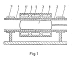
- the pipe sections (1) and (2) which are cut off vertically at the ends, are fixed to one another in a clamping device of any design.
- a clamping device of any design.
- it can consist of two prism-shaped supports mounted on a common frame, on which the pipe pieces are fastened with clamping rings (7) and (7 ').
- a lightweight construction is advantageous, which allows handling without additional aids, even with freely suspended pipelines. Centering devices for aligning the pipe sections are not required.
- the inner support device (3) shown in the drawing as a rubber bellows, is either inserted when the pipe sections are clamped in or subsequently inserted into the connection point using a suitable device.
- the diameter is designed in such a way that it is easy to insert even when the piping is curved and large lengths are involved.
- a short compressed air hose which can be connected to a flexible pipe of any length via a coupling valve, the diameter of the rubber bellows can be adjusted by applying a pressure medium, e.g. Water or air, at least up to the size of the pipe inside diameter.
- the coupled pipe is used to insert and pull out the rubber bellows and at the same time as a pressure medium supply.
- the divided outer shape (4) consists of two half-shells adapted to the tube outer diameter, which can be adjusted using suitable devices, e.g. Quick-release fasteners are connected and placed non-positively around the pipe ends. Due to the execution in brass or similar. good thermal conductivity is achieved.
- the middle chamber (5) preferably contains electrical heating elements.
- the outer cooling chambers (6) and (6 ') are for the passage of a cooling medium, e.g. Water or air. In the drawing, the electrical and coolant connections as well as the commonly used measuring and control devices are omitted.
- the chambers (6 ') and (6) can optionally be separated from the chamber (5) by a heat insulation layer (not shown).
- the required internal pressure which is maintained during the entire welding process, is determined in preliminary tests.
- the required heating capacity (variable in voltage level and duration) and cooling capacity (flow quantity and duration) are also determined. After assembling the mold, these sizes are put in by hand or the parameters set in a program control are started. After the specified time has elapsed, the finished connection point can be removed from the mold in a simple manner.
Description
- Es ist bekannt, thermoplastische Kunststoffhohlprofile, insbesondere Rohre, durch Stumpfschweißen zu verbinden. Die bekannten Verfahren arbeiten alle nach dem Prinzip, daß die Stirnfläche des Profils erwärmt und damit plastifiziert wird. Anschließend werden die so erwärmten und plastifizierten Stirnflächen zusammengestoßen und damit verschmolzen. Diese Verfahren haben alle den Nachteil, daß an der Schweißnaht Schweißwulste sowohl außen als auch im Innern des Profils auftreten. Derartige Schweißwulste sind vor allem bei Getränkeleitungen unerwünscht, da an diesen Stellen leicht Ablagerungen stattfinden und die Leitungen sich auch wesentlich schwerer reinigen lassen. Aus der DE-A-2316500 ist bekannt, daß man die Schweißwulste abklemmen kann. Eine solche Arbeitsweise kann nicht befriedigen, da zur Erzielung glatter Oberflächen die Schweißstellen nachbearbeitet werden müssen. Auf das Profilinnere ist dieses Verfahren überhaupt nicht anwendbar.
- Aus der DE-A-26 33 141 ist ein Verfahren bekannt, bei dem man einen Hohlkörper im Innern des Hohlprofils anbringt. Nach dem Erwärmen der Profilstirnflächen werden diese zusammengestaucht. Mittels beiderseits des Hohlkörpers im Inneren ebenfalls angebrachter Absperrvorrichtungen ist es möglich, in diesem Bereich einen Unterdruck zu erzeugen, durch den das Profil über den ganzen Umfang auf dem etwas kleiner dimensionierten Hohlkörper zum Anliegen gebracht werden soll. Nach Beendigung der Verschweißung werden die Profilstücke etwas auseinandergezogen, wodurch die beim Zusammenstauchen eingetretene Verdickung wieder verringert werden soll. Außerdem wird zur Herstellung des ursprünglichen Profildurchmessers und als Voraussetzung zur Entfernung des Hohlkörpers und der Absperrvorrichtungen durch Überdruck das Profil wieder aufgeweitet. Die vorhandenen Außenschweißwulste müssen nachträglich abgearbeitet bzw. geglättet werden.
- Aus der CH-A-455 254 ist ein Verfahren zum nahtlosen Verbinden von thermoplastischen Kunststoffhohlprofilen durch Plastifizieren der auf Stoß eingespannten, zu verbindenden Profilendstücke bekannt, wobei unter Verwenden einer die Endstücke vollständig umschließenden Außenform und einer im Inneren der Hohlprofile verschiebbaren Stützvorrichtung gearbeitet wird.
- Nach dieser Arbeitsweise ist es sowohl erforderlich, die Profilenden vorzuwärmen, ehe sie in die Form eingespannt werden, als auch anschließend einen erheblichen Preßdruck zum Zusammenstauchen der Profilstücke aufzuwenden. Das Verfahren des Standes der Technik ist nur zum Verbinden von kurzen Rohrstücken geeignet, wobei eine erhebliche Längenverkürzung durch das Zusammenstauchen auftritt. Außerdem ist ein Nacharbeiten der Verbindungsnaht erforderlich, da die beim Stauchen an der Verbindungsnaht austretende Masse auf der Oberfläche des Hohlprofils ungleichmäßig verteilt wird.
- Aufgabe der Erfindung ist es, ein einfach handhabbares Verfahren zum nahtlosen Verbinden von thermoplastischen Kunststoffhohlprofilen bereitzustellen, wobei durch Plastifizieren der auf Stoß eingespannten zu verbindenden Profilendstücke diese unter Verwendung einer die Endstükke vollständig umschließenden Außenform und einer im Innern der Hohlprofile verschiebbaren Stützvorrichtung verbunden werden, und welches auf einfache Weise erlaubt, nahtlose und schweißwulstlose Verbindungen von Hohlprofilen herzustellen, wobei sowohl im Innern als auch außen keine Schweißwülste auftreten und demnach eine Nachbehandlung und eine Längenänderung der Profile vermieden wird.
- Die Lösung der Aufgabe gelingt, wenn man die zu verbindenden, auf Stoß eingespannten Endstücke der Hohlprofile mittels einer beheiz- und teilbaren, die Profilendstücke vollkommen umschließenden Außenform plastifiziert und gleichzeitig eine Volumen veränderbare, unter Überdruck gehaltene Stützvorrichtung einbringt, die sich glatt an die Innenwand der Hohlprofile anlegt.
- Insbesondere ist die Arbeitsweise geeignet bei Einkammerprofilen, besonders Rohren. Die äußere, das Profil umschließende Form besteht vorteilhaft aus mindestens zwei Metallhalbschalen, die beheizbar sind. Insbesondere werden diese Halbschalen so eingerichtet, daß der innere Teil zur Stoßnaht beheizbar ist und der äußere Teil an beiden Enden, jeweils in Längsrichtung des Profils betrachtet, mit Kühlkammern ausgerüstet ist. Diese das Profil vollkommen umschließende Form erlaubt das vollkommene Durchplastifizieren der eingespannten Endstücke. Als zweiter notwendiger Teil befindet sich im Innern des Hohlprofils eine in ihrem Volumen veränderbare Stützvorrichtung, die sich glatt an die Innenfläche des Hohlprofils anlegt, beispielsweise ein aufblasbarer Gummibalg mit nichthaftender Oberfläche.
- Die Profilenden werden demnach von außen beheizt und durchplastifiziert, durch die vorhandene Kühlzone bleiben jedoch die weiter abliegenden Profilteile starr. Der durch die Wärmeausdehnung auftretende Druck verbindet die Profilenden homogen. Nach dem Erkalten und Entformen liegt eine glatte nahtlose Verbindung vor, sowohl im Innern des Profils als auch auf der Außenfläche.
- Als Vorteile gegenüber dem Stand der Technik sind z.B. zu nennen :
- a) Es ist eine einfachere, leichte, transportable Einspannvorrichtung ohne verfahrbare Teile verwendbar
- . b) Nachdem in Vorversuchen die erforderlichen Heiz- und Kühlleistungen bzw. -zeiten ermittelt worden sind, ist nach dem Einrichten der Schweißstelle ein automatischer Ablauf ohne weitere Handgriffe gegeben
- c) Auch bei Querschnittsabweichungen der Fügeteile tritt kein Versatz an den Stoßstellen auf. Eine bei Rohren gegebenenfalls vorhandene Ovalität wird ohne zusätzliche Maßnahmen ausgeglichen
- d) Die Ausgangslänge der Fügeteile bleibt genau erhalten
- e) Ein Nacharbeiten der Schweißstelle ist nicht erforderlich
- f) Infolge der außen und innen nahtlosen, glatten Verbindung ergeben sich bei Rohrleitungen keine Durchflußbehinderungen und problemlose Reinigungsmöglichkeiten
- g) Das Verfahren ist bei Reparaturarbeiten an bestehenden Leitungen oder beim Verbinden gekrümmter Profile, z.B. Rohrbogen, ebenfalls verwendbar, da die innere Stützvorrichtung auch hier problemlos eingeführt werden kann
- h) Festigkeitsmindernde Verunreinigungen in der Schweißnaht werden vermieden, wie sie beim Heizelementschweißen durch verbleibende Rückstände am Heizelement oder beim Warmgasschweißen durch thermischoxidativen Abbau auftreten können.
- Anhand der Fig. 1, die schematisch einen Längsschnitt der Vorrichtung in einer Ausführungsform zeigt, wird das Verfahren am Beispiel der Verschweißung von Rohren beschrieben.
- Die an den Enden senkrecht abgeschnittenen Rohrstücke (1) und (2) werden auf Stoß in einer beliebig gestalteten Einspannvorrichtung fixiert. Sie kann im einfachsten Fall aus zwei auf einem gemeinsamen Rahmen montierten, prismenförmigen Auflagen bestehen, auf denen die Rohrstücke mit Spannringen (7) und (7') befestigt werden. Vorteilhaft ist eine leichte Bauweise, die die Handhabung ohne weitere Hilfsmittel auch bei freihängenden Rohrleitungen erlaubt. Zentriervorrichtungen zum Ausrichten der Rohrstücke sind nicht erforderlich.
- Die innere Stützvorrichtung (3), in der Zeichnung als Gummibalg dargestellt, wird entweder beim Einspannen der Rohrstücke eingebracht oder nachträglich mit einer geeigneten Vorrichtung an die Verbindungsstelle eingeschoben. Der Durchmesser ist so ausgelegt, daß auch bei Krümmungen der Rohrleitung und großen Längen ein bequemes Einführen möglich ist. Über einen angesetzten kurzen Druckluftschlauch, der über ein Kupplungsventil mit einem flexiblen Rohr beliebiger Länge verbunden werden kann, kann der Durchmesser des Gummibalgs durch Aufgeben eines Druckmediums, z.B. Wasser oder Luft, mindestens bis zur Größe des Rohrinnendurchmessers aufgeweitet werden. Das angekuppelte Rohr dient zum Einführen und Herausziehen des Gummibalgs und gleichzeitig als Druckmittelzuführung. Die beliebig ausgeführten Druckerzeuger und mögliche Meß- und Regeleinrichtungen sind in der Zeichnung weggelassen. Bei Aufgabe des Innendruckes ist es unter Umständen nützlich, wenn der Gummibalg keine Längenausdehnung erfährt. Dies kann gegebenenfalls durch eine entsprechende Ausführung mit Gewebeeinlagen oder andere Maßnahmen, z.B. das Anbringen von stirnseitigen Verstärkungsplatten, die über durch das Innere gehende Zuganker verbunden sind, erreicht werden.
- Die geteilte Außenform (4) besteht aus zwei dem Rohraußendurchmesser angepaßten Halbschalen, die über geeignete Vorrichtungen, z.B. Schnellspannverschlüsse verbunden, kraftschlüssig um die Rohrenden gelegt werden. Durch die Ausführung in Messing o.ä. wird eine gute Wärmeleitfähigkeit erreicht. Die mittlere Kammer (5) enthält vorzugsweise elektrische Heizelemente. Die äußeren Kühlkammern (6) und (6') sind zum Durchleiten eines Kühlmediums, z.B. Wasser oder Luft, eingerichtet. In der Zeichnung sind die elektrischen und Kühlmittelanschlüsse sowie die üblicherweise verwendeten Meß- und Regeleinrichtungen weggelassen. Die Kammern (6') und (6) können von kammer (5) gegebenenfalls durch eine nicht eingezeichnete Wärmeisolierschicht getrennt sein.
- In Vorversuchen wird der erforderliche Innendruck, der während des gesamten Schweißvorganges aufrechterhalten wird, bestimmt. Ebenso wird die benötigte Heizleistung (variabel in Spannungshöhe und Zeitdauer) und Kühlleistung (Durchflußmenge und -dauer) ermittelt. Nach Zusammenbau der Form werden diese Größen von Hand aufgegeben oder auch die in einer Programmsteuerung eingestellten Parameter gestartet. Nach Ablauf der vorgegebenen Zeit kann die fertige Verbindungsstelle auf einfache Weise entformt werden.
Claims (3)
Priority Applications (1)
| Application Number | Priority Date | Filing Date | Title |
|---|---|---|---|
| AT80102097T ATE2303T1 (de) | 1979-06-08 | 1980-04-18 | Verfahren zum nahtlosen verbinden von thermoplastischen kunststoffhohlprofilen und vorrichtung zur durchfuehrung des verfahrens. |
Applications Claiming Priority (2)
| Application Number | Priority Date | Filing Date | Title |
|---|---|---|---|
| DE2923205A DE2923205C2 (de) | 1979-06-08 | 1979-06-08 | Verfahren und Vorrichtung zum nahtlosen Verbinden von thermoplastischen Kunststoffhohlprofilen |
| DE2923205 | 1979-06-08 |
Publications (2)
| Publication Number | Publication Date |
|---|---|
| EP0020915A1 EP0020915A1 (de) | 1981-01-07 |
| EP0020915B1 true EP0020915B1 (de) | 1983-01-26 |
Family
ID=6072747
Family Applications (1)
| Application Number | Title | Priority Date | Filing Date |
|---|---|---|---|
| EP80102097A Expired EP0020915B1 (de) | 1979-06-08 | 1980-04-18 | Verfahren zum nahtlosen Verbinden von thermoplastischen Kunststoffhohlprofilen und Vorrichtung zur Durchführung des Verfahrens |
Country Status (4)
| Country | Link |
|---|---|
| EP (1) | EP0020915B1 (de) |
| JP (1) | JPS56118A (de) |
| AT (1) | ATE2303T1 (de) |
| DE (1) | DE2923205C2 (de) |
Families Citing this family (22)
| Publication number | Priority date | Publication date | Assignee | Title |
|---|---|---|---|---|
| DE3426246A1 (de) * | 1984-07-17 | 1986-01-30 | Krings International Inh. Josef Krings, 5138 Heinsberg | Verfahren und vorrichtung zum anschliessen seitlicher stutzen oder querleitungen an ein hauptleitungsrohr |
| CA1271160A (en) * | 1985-05-16 | 1990-07-03 | Joel L. Williams | Ionizing plasma lubricant method |
| EP0263980A3 (de) * | 1986-10-14 | 1990-01-31 | Georg Fischer Aktiengesellschaft | Vorrichtung und Verfahren zum Schmelzverbinden von Kunststoffrohren |
| DE3636891A1 (de) * | 1986-10-30 | 1988-05-11 | Armin Dommer | Verfahren und vorrichtung zum stumpfschweissen von kunststoff-rohrabschnitten oder kunststoff-formstuecken |
| DE3640105A1 (de) * | 1986-11-24 | 1988-06-01 | Kurt Peitz | Verfahren zum verschweissen von kunststoffrohren |
| DE3708705A1 (de) * | 1987-03-18 | 1988-10-06 | Gruber Alois & Sohn Agru | Verfahren und vorrichtung zum verschweissen rohrfoermiger kunststoffteile |
| US4792374B1 (en) * | 1987-04-03 | 1995-02-14 | Fischer Ag Georg | Apparatus for fusion joining plastic pipe |
| CH673619A5 (de) * | 1987-08-28 | 1990-03-30 | Fischer Ag Georg | |
| CH673432A5 (de) * | 1987-09-23 | 1990-03-15 | Fischer Ag Georg | |
| CH675391A5 (de) * | 1988-07-04 | 1990-09-28 | Fischer Ag Georg | |
| CH676689A5 (de) * | 1988-08-16 | 1991-02-28 | Fischer Ag Georg | |
| DE3911544A1 (de) * | 1989-04-08 | 1990-10-11 | Armin Dommer | Verfahren und vorrichtung zum stumpfschweissen von zwei kunststoff-rohrabschnitten oder kunststoff-formstuecken |
| JPH0558264U (ja) * | 1992-01-17 | 1993-08-03 | 呉羽化学工業株式会社 | ビード発生防止装置及びそれを用いた突合せ溶接装置 |
| JPH05318596A (ja) * | 1992-05-27 | 1993-12-03 | Sekisui Chem Co Ltd | 熱可塑性樹脂管と電気融着継手の接合方法 |
| US5484506A (en) * | 1994-05-16 | 1996-01-16 | Sani-Tech Incorporated | Smooth bore welding of thermoplastic tubing |
| DE4428767C2 (de) * | 1994-08-13 | 1996-09-05 | Rehau Ag & Co | Verfahren zum Verschweissen von Rohrmuffen |
| US6086806A (en) * | 1996-04-05 | 2000-07-11 | Ronald H. Ball | Method of splicing thermoplastic articles |
| ID20783A (id) * | 1997-09-01 | 1999-03-04 | Fischer Georg Rohrleitung | Metode pengelasan bersama-sama, benda-benda yang terbuat dari bahan plastik |
| US6289912B1 (en) * | 1998-07-10 | 2001-09-18 | Fluoroware, Inc. | Pinch element plastic valve |
| DE19905623A1 (de) * | 1999-02-11 | 2000-08-17 | Asea Brown Boveri | Verfahren zur Herstellung eines thermoplastischen Kunststoffrohrs, nach diesem Verfahren hergestelltes Rohr und Verwendung dieses Rohrs |
| DE102006013008C5 (de) * | 2005-03-18 | 2013-12-19 | Gerodur Mpm Kunststoffverarbeitung Gmbh & Co Kg | Verfahren zum Herstellen einer Stumpfschweißverbindung von Schutzmantelrohren |
| CN109968683A (zh) * | 2017-12-28 | 2019-07-05 | 上海宝冶集团有限公司 | 热塑性塑料热熔连接翻边控制装置及其使用方法 |
Family Cites Families (5)
| Publication number | Priority date | Publication date | Assignee | Title |
|---|---|---|---|---|
| US3035958A (en) * | 1959-11-05 | 1962-05-22 | Phillips Petroleum Co | Method of joining polyethylene pipe |
| CH455254A (de) * | 1966-04-15 | 1968-06-28 | Keller Roehren Ag | Verfahren zum Verschweissen thermoplastischer Kunststoffteile |
| IE36215B1 (en) * | 1971-03-26 | 1976-09-15 | Wavin Bv | A method of and apparatus for forming an internal groove in a tubular plastics member |
| NL7206836A (de) * | 1972-05-19 | 1973-11-21 | ||
| DE2633141A1 (de) * | 1976-07-23 | 1978-01-26 | Peter Dipl Chem Dr Eckardt | Verfahren und vorrichtung zum stirnseitigen verschweissen von thermoplastischen kunststoffhohlprofilen |
-
1979
- 1979-06-08 DE DE2923205A patent/DE2923205C2/de not_active Expired
-
1980
- 1980-04-18 EP EP80102097A patent/EP0020915B1/de not_active Expired
- 1980-04-18 AT AT80102097T patent/ATE2303T1/de not_active IP Right Cessation
- 1980-06-09 JP JP7675280A patent/JPS56118A/ja active Pending
Also Published As
| Publication number | Publication date |
|---|---|
| DE2923205A1 (de) | 1980-12-18 |
| EP0020915A1 (de) | 1981-01-07 |
| JPS56118A (en) | 1981-01-06 |
| DE2923205C2 (de) | 1982-12-16 |
| ATE2303T1 (de) | 1983-02-15 |
Similar Documents
| Publication | Publication Date | Title |
|---|---|---|
| EP0020915B1 (de) | Verfahren zum nahtlosen Verbinden von thermoplastischen Kunststoffhohlprofilen und Vorrichtung zur Durchführung des Verfahrens | |
| EP0355579B1 (de) | Verfahren und Einrichtung zum Verschweissen von rohrförmigen Teilen aus Kunststoff | |
| DE1704124B1 (de) | Verfahren und vorrichtung zum anformen eines bodensam ende eines thermoplastischen kunststoffrohres | |
| DE3636891A1 (de) | Verfahren und vorrichtung zum stumpfschweissen von kunststoff-rohrabschnitten oder kunststoff-formstuecken | |
| DE4423372A1 (de) | Verfahren und Vorrichtung zum Anformen von Flanschen an Rohre aus teilkristallinen Thermoplasten | |
| DE2628203A1 (de) | Verfahren zur ultraschallverschweissung von zwei thermoplastischen werkstuecken | |
| EP0415068B1 (de) | Einrichtung und Verfahren zum Verschweissen rohrförmiger Teile aus thermoplastischem Material | |
| CH675391A5 (de) | ||
| DE2502181A1 (de) | Verfahren zum verbinden von rohren aus thermoplastischem kunststoff mit plattenboeden aus thermoplastischem kunststoff | |
| DE102005050571A1 (de) | Verfahren und Vorrichtung zum Verschweißen von Kunststoffform- bzw. Kunststoffhohlkörpern | |
| DE10238550B4 (de) | Vorrichtung zum Verschweißen von thermoplastischen Rohrelementen | |
| DE2349818B2 (de) | Verfahren zum anformen eines flansches an einem ende eines in einem metallrohr angeordneten auskleidungsrohres | |
| DE3911544C2 (de) | ||
| DE2212055B2 (de) | Vorrichtung zum Verschweißen von koaxial liegenden Rohren aus thermoplastischem Kunststoff | |
| EP0074456A1 (de) | Verfahren zum Herstellen von Muffen od. dgl. an rohrförmigen Werkstücken aus Thermoplasten und Vorrichtung zur Durchführung des Verfahrens | |
| DE4136349A1 (de) | Schweissvorrichtung fuer kunststoffrohre | |
| DE3904838A1 (de) | Rohrverbindung, insbesondere fuer kunststoffrohre und -schlaeuche oder dergleichen sowie verfahren und vorrichtung zu ihrer herstellung | |
| DE60309696T2 (de) | Verfahren und system zur herstellung eines zweigs in einem polymerrohr unter verwendung erwärmter flüssigkeit zur plastifizierung eines rohrwandabschnitts, der zur bildung des zweigs nach aussen verschoben werden soll | |
| AT392149B (de) | Verfahren zum verbinden isolierter leitungsrohre | |
| CH667316A5 (en) | Welding together two outer plastic tubes - by joining them with two part heated ring between until ends melt, removing ring, and pressing ends together | |
| DE1962737C (de) | Verfahren und Vorrichtung zur Herstel lung einer Muffe am Ende eines Rohres aus schweißbarem Kunststoff | |
| DE2619935A1 (de) | Vorrichtung zum verschweissen von schlauchstuecken, insbesondere von vakuumfesten schlaeuchen aus thermoplastischem kunststoff | |
| DE2410929B2 (de) | Verfahren und Vorrichtung zum Herstellen eines Abzweigformstückes aus thermoplastischem Kunststoff | |
| DE202013009206U1 (de) | Schweißbasis für eine Schweißvorrichtung zur Herstellung einer Schweißverbindung zwischen Kunststoffrohren | |
| DD242779A1 (de) | Verfahren und anordnung zum verschweissen thermoplastischer werkstoffe |
Legal Events
| Date | Code | Title | Description |
|---|---|---|---|
| PUAI | Public reference made under article 153(3) epc to a published international application that has entered the european phase |
Free format text: ORIGINAL CODE: 0009012 |
|
| AK | Designated contracting states |
Designated state(s): AT CH FR GB IT NL |
|
| 17P | Request for examination filed |
Effective date: 19801205 |
|
| ITF | It: translation for a ep patent filed |
Owner name: SOCIETA' ITALIANA BREVETTI S.P.A. |
|
| GRAA | (expected) grant |
Free format text: ORIGINAL CODE: 0009210 |
|
| AK | Designated contracting states |
Designated state(s): AT CH FR GB IT NL |
|
| REF | Corresponds to: |
Ref document number: 2303 Country of ref document: AT Date of ref document: 19830215 Kind code of ref document: T |
|
| ET | Fr: translation filed | ||
| PGFP | Annual fee paid to national office [announced via postgrant information from national office to epo] |
Ref country code: FR Payment date: 19830406 Year of fee payment: 4 |
|
| PGFP | Annual fee paid to national office [announced via postgrant information from national office to epo] |
Ref country code: CH Payment date: 19830426 Year of fee payment: 4 |
|
| PGFP | Annual fee paid to national office [announced via postgrant information from national office to epo] |
Ref country code: NL Payment date: 19830429 Year of fee payment: 4 Ref country code: AT Payment date: 19830429 Year of fee payment: 4 |
|
| PG25 | Lapsed in a contracting state [announced via postgrant information from national office to epo] |
Ref country code: AT Effective date: 19840418 |
|
| PG25 | Lapsed in a contracting state [announced via postgrant information from national office to epo] |
Ref country code: LI Effective date: 19840430 Ref country code: CH Effective date: 19840430 |
|
| PG25 | Lapsed in a contracting state [announced via postgrant information from national office to epo] |
Ref country code: NL Effective date: 19841101 |
|
| GBPC | Gb: european patent ceased through non-payment of renewal fee | ||
| NLV4 | Nl: lapsed or anulled due to non-payment of the annual fee | ||
| PG25 | Lapsed in a contracting state [announced via postgrant information from national office to epo] |
Ref country code: FR Free format text: LAPSE BECAUSE OF NON-PAYMENT OF DUE FEES Effective date: 19841228 |
|
| REG | Reference to a national code |
Ref country code: CH Ref legal event code: PL |
|
| REG | Reference to a national code |
Ref country code: FR Ref legal event code: ST |
|
| PG25 | Lapsed in a contracting state [announced via postgrant information from national office to epo] |
Ref country code: GB Effective date: 19881118 |
|
| PLBE | No opposition filed within time limit |
Free format text: ORIGINAL CODE: 0009261 |
|
| STAA | Information on the status of an ep patent application or granted ep patent |
Free format text: STATUS: NO OPPOSITION FILED WITHIN TIME LIMIT |