EP0018924B1 - Verfahren zur Herstellung von Solarzellenpaneelen und durch dieses Verfahren erhaltene Paneele - Google Patents
Verfahren zur Herstellung von Solarzellenpaneelen und durch dieses Verfahren erhaltene Paneele Download PDFInfo
- Publication number
- EP0018924B1 EP0018924B1 EP80400619A EP80400619A EP0018924B1 EP 0018924 B1 EP0018924 B1 EP 0018924B1 EP 80400619 A EP80400619 A EP 80400619A EP 80400619 A EP80400619 A EP 80400619A EP 0018924 B1 EP0018924 B1 EP 0018924B1
- Authority
- EP
- European Patent Office
- Prior art keywords
- photocells
- layer
- sheet
- rigid
- powder
- Prior art date
- Legal status (The legal status is an assumption and is not a legal conclusion. Google has not performed a legal analysis and makes no representation as to the accuracy of the status listed.)
- Expired
Links
- 238000000034 method Methods 0.000 title claims description 28
- 238000004519 manufacturing process Methods 0.000 title claims description 15
- 239000000843 powder Substances 0.000 claims description 41
- 229920002037 poly(vinyl butyral) polymer Polymers 0.000 claims description 33
- 229920005989 resin Polymers 0.000 claims description 27
- 239000011347 resin Substances 0.000 claims description 27
- 239000004014 plasticizer Substances 0.000 claims description 17
- 239000000463 material Substances 0.000 claims description 16
- 239000011521 glass Substances 0.000 claims description 15
- 229920005992 thermoplastic resin Polymers 0.000 claims description 13
- 229920001169 thermoplastic Polymers 0.000 claims description 11
- 239000004416 thermosoftening plastic Substances 0.000 claims description 11
- 239000000203 mixture Substances 0.000 claims description 8
- 238000010438 heat treatment Methods 0.000 claims description 6
- 239000012815 thermoplastic material Substances 0.000 claims description 6
- 238000002844 melting Methods 0.000 claims description 4
- 230000008018 melting Effects 0.000 claims description 4
- 229920003023 plastic Polymers 0.000 claims description 4
- 238000005245 sintering Methods 0.000 claims description 4
- 239000004033 plastic Substances 0.000 claims description 3
- 230000004927 fusion Effects 0.000 claims description 2
- 238000011065 in-situ storage Methods 0.000 claims description 2
- 238000003825 pressing Methods 0.000 claims description 2
- 239000000470 constituent Substances 0.000 claims 1
- 230000000694 effects Effects 0.000 claims 1
- 239000011248 coating agent Substances 0.000 description 6
- 238000000576 coating method Methods 0.000 description 6
- ZIBGPFATKBEMQZ-UHFFFAOYSA-N triethylene glycol Chemical compound OCCOCCOCCO ZIBGPFATKBEMQZ-UHFFFAOYSA-N 0.000 description 6
- NIXOWILDQLNWCW-UHFFFAOYSA-N acrylic acid group Chemical group C(C=C)(=O)O NIXOWILDQLNWCW-UHFFFAOYSA-N 0.000 description 4
- XUIMIQQOPSSXEZ-UHFFFAOYSA-N Silicon Chemical compound [Si] XUIMIQQOPSSXEZ-UHFFFAOYSA-N 0.000 description 3
- 229910052782 aluminium Inorganic materials 0.000 description 3
- XAGFODPZIPBFFR-UHFFFAOYSA-N aluminium Chemical compound [Al] XAGFODPZIPBFFR-UHFFFAOYSA-N 0.000 description 3
- 230000007547 defect Effects 0.000 description 3
- 238000009434 installation Methods 0.000 description 3
- 238000007789 sealing Methods 0.000 description 3
- 229910052710 silicon Inorganic materials 0.000 description 3
- 239000010703 silicon Substances 0.000 description 3
- IHLDEDLAZNFOJB-UHFFFAOYSA-N 6-octoxy-6-oxohexanoic acid Chemical compound CCCCCCCCOC(=O)CCCCC(O)=O IHLDEDLAZNFOJB-UHFFFAOYSA-N 0.000 description 2
- RYGMFSIKBFXOCR-UHFFFAOYSA-N Copper Chemical compound [Cu] RYGMFSIKBFXOCR-UHFFFAOYSA-N 0.000 description 2
- LFQSCWFLJHTTHZ-UHFFFAOYSA-N Ethanol Chemical compound CCO LFQSCWFLJHTTHZ-UHFFFAOYSA-N 0.000 description 2
- 239000000654 additive Substances 0.000 description 2
- 125000001797 benzyl group Chemical group [H]C1=C([H])C([H])=C(C([H])=C1[H])C([H])([H])* 0.000 description 2
- 229910052802 copper Inorganic materials 0.000 description 2
- 239000010949 copper Substances 0.000 description 2
- 235000019441 ethanol Nutrition 0.000 description 2
- 230000002093 peripheral effect Effects 0.000 description 2
- 238000006116 polymerization reaction Methods 0.000 description 2
- 230000008569 process Effects 0.000 description 2
- 239000004065 semiconductor Substances 0.000 description 2
- 229920002050 silicone resin Polymers 0.000 description 2
- 239000000243 solution Substances 0.000 description 2
- 238000005507 spraying Methods 0.000 description 2
- 238000003892 spreading Methods 0.000 description 2
- 230000007480 spreading Effects 0.000 description 2
- 239000005341 toughened glass Substances 0.000 description 2
- XLYOFNOQVPJJNP-UHFFFAOYSA-N water Substances O XLYOFNOQVPJJNP-UHFFFAOYSA-N 0.000 description 2
- WSLDOOZREJYCGB-UHFFFAOYSA-N 1,2-Dichloroethane Chemical compound ClCCCl WSLDOOZREJYCGB-UHFFFAOYSA-N 0.000 description 1
- UBQXQCCAPASFJR-UHFFFAOYSA-N 2-[2-(2-nonanoyloxyethoxy)ethoxy]ethyl nonanoate Chemical compound CCCCCCCCC(=O)OCCOCCOCCOC(=O)CCCCCCCC UBQXQCCAPASFJR-UHFFFAOYSA-N 0.000 description 1
- WUPHOULIZUERAE-UHFFFAOYSA-N 3-(oxolan-2-yl)propanoic acid Chemical compound OC(=O)CCC1CCCO1 WUPHOULIZUERAE-UHFFFAOYSA-N 0.000 description 1
- MARUHZGHZWCEQU-UHFFFAOYSA-N 5-phenyl-2h-tetrazole Chemical compound C1=CC=CC=C1C1=NNN=N1 MARUHZGHZWCEQU-UHFFFAOYSA-N 0.000 description 1
- 229910000838 Al alloy Inorganic materials 0.000 description 1
- PYGXAGIECVVIOZ-UHFFFAOYSA-N Dibutyl decanedioate Chemical compound CCCCOC(=O)CCCCCCCCC(=O)OCCCC PYGXAGIECVVIOZ-UHFFFAOYSA-N 0.000 description 1
- GYHNNYVSQQEPJS-UHFFFAOYSA-N Gallium Chemical compound [Ga] GYHNNYVSQQEPJS-UHFFFAOYSA-N 0.000 description 1
- GPXJNWSHGFTCBW-UHFFFAOYSA-N Indium phosphide Chemical compound [In]#P GPXJNWSHGFTCBW-UHFFFAOYSA-N 0.000 description 1
- BQCADISMDOOEFD-UHFFFAOYSA-N Silver Chemical compound [Ag] BQCADISMDOOEFD-UHFFFAOYSA-N 0.000 description 1
- 239000002253 acid Substances 0.000 description 1
- 150000007513 acids Chemical class 0.000 description 1
- 239000003522 acrylic cement Substances 0.000 description 1
- 230000009471 action Effects 0.000 description 1
- 239000000853 adhesive Substances 0.000 description 1
- 230000001070 adhesive effect Effects 0.000 description 1
- WNLRTRBMVRJNCN-UHFFFAOYSA-N adipic acid Chemical class OC(=O)CCCCC(O)=O WNLRTRBMVRJNCN-UHFFFAOYSA-N 0.000 description 1
- 150000001298 alcohols Chemical class 0.000 description 1
- 125000000217 alkyl group Chemical group 0.000 description 1
- 229910045601 alloy Inorganic materials 0.000 description 1
- 239000000956 alloy Substances 0.000 description 1
- -1 aryl adipates Chemical class 0.000 description 1
- 230000008901 benefit Effects 0.000 description 1
- IHTSDBYPAZEUOP-UHFFFAOYSA-N bis(2-butoxyethyl) hexanedioate Chemical compound CCCCOCCOC(=O)CCCCC(=O)OCCOCCCC IHTSDBYPAZEUOP-UHFFFAOYSA-N 0.000 description 1
- 229910052980 cadmium sulfide Inorganic materials 0.000 description 1
- 238000003490 calendering Methods 0.000 description 1
- 230000015556 catabolic process Effects 0.000 description 1
- 230000008859 change Effects 0.000 description 1
- 238000005238 degreasing Methods 0.000 description 1
- 238000000151 deposition Methods 0.000 description 1
- 239000003599 detergent Substances 0.000 description 1
- 230000006866 deterioration Effects 0.000 description 1
- 238000001035 drying Methods 0.000 description 1
- 230000008030 elimination Effects 0.000 description 1
- 238000003379 elimination reaction Methods 0.000 description 1
- 238000005538 encapsulation Methods 0.000 description 1
- 150000002148 esters Chemical class 0.000 description 1
- 238000000605 extraction Methods 0.000 description 1
- 238000011049 filling Methods 0.000 description 1
- 229910052733 gallium Inorganic materials 0.000 description 1
- 239000007789 gas Substances 0.000 description 1
- 125000002887 hydroxy group Chemical group [H]O* 0.000 description 1
- 238000002347 injection Methods 0.000 description 1
- 239000007924 injection Substances 0.000 description 1
- 229910000765 intermetallic Inorganic materials 0.000 description 1
- 238000004898 kneading Methods 0.000 description 1
- OJXOOFXUHZAXLO-UHFFFAOYSA-M magnesium;1-bromo-3-methanidylbenzene;bromide Chemical compound [Mg+2].[Br-].[CH2-]C1=CC=CC(Br)=C1 OJXOOFXUHZAXLO-UHFFFAOYSA-M 0.000 description 1
- 239000003607 modifier Substances 0.000 description 1
- 229910021421 monocrystalline silicon Inorganic materials 0.000 description 1
- 229920003229 poly(methyl methacrylate) Polymers 0.000 description 1
- 229920000058 polyacrylate Polymers 0.000 description 1
- 229910021420 polycrystalline silicon Inorganic materials 0.000 description 1
- 229920001223 polyethylene glycol Polymers 0.000 description 1
- 239000004926 polymethyl methacrylate Substances 0.000 description 1
- 238000004080 punching Methods 0.000 description 1
- 238000005070 sampling Methods 0.000 description 1
- 239000004447 silicone coating Substances 0.000 description 1
- 229910052709 silver Inorganic materials 0.000 description 1
- 239000004332 silver Substances 0.000 description 1
- 239000003381 stabilizer Substances 0.000 description 1
- 229920003002 synthetic resin Polymers 0.000 description 1
- 239000000057 synthetic resin Substances 0.000 description 1
- 239000006188 syrup Substances 0.000 description 1
- 235000020357 syrup Nutrition 0.000 description 1
- 239000012780 transparent material Substances 0.000 description 1
- 229920006352 transparent thermoplastic Polymers 0.000 description 1
Images

Classifications
-
- B—PERFORMING OPERATIONS; TRANSPORTING
- B32—LAYERED PRODUCTS
- B32B—LAYERED PRODUCTS, i.e. PRODUCTS BUILT-UP OF STRATA OF FLAT OR NON-FLAT, e.g. CELLULAR OR HONEYCOMB, FORM
- B32B17/00—Layered products essentially comprising sheet glass, or glass, slag, or like fibres
- B32B17/06—Layered products essentially comprising sheet glass, or glass, slag, or like fibres comprising glass as the main or only constituent of a layer, next to another layer of a specific material
- B32B17/10—Layered products essentially comprising sheet glass, or glass, slag, or like fibres comprising glass as the main or only constituent of a layer, next to another layer of a specific material of synthetic resin
- B32B17/10005—Layered products essentially comprising sheet glass, or glass, slag, or like fibres comprising glass as the main or only constituent of a layer, next to another layer of a specific material of synthetic resin laminated safety glass or glazing
- B32B17/1055—Layered products essentially comprising sheet glass, or glass, slag, or like fibres comprising glass as the main or only constituent of a layer, next to another layer of a specific material of synthetic resin laminated safety glass or glazing characterized by the resin layer, i.e. interlayer
- B32B17/10761—Layered products essentially comprising sheet glass, or glass, slag, or like fibres comprising glass as the main or only constituent of a layer, next to another layer of a specific material of synthetic resin laminated safety glass or glazing characterized by the resin layer, i.e. interlayer containing vinyl acetal
-
- B—PERFORMING OPERATIONS; TRANSPORTING
- B32—LAYERED PRODUCTS
- B32B—LAYERED PRODUCTS, i.e. PRODUCTS BUILT-UP OF STRATA OF FLAT OR NON-FLAT, e.g. CELLULAR OR HONEYCOMB, FORM
- B32B17/00—Layered products essentially comprising sheet glass, or glass, slag, or like fibres
- B32B17/06—Layered products essentially comprising sheet glass, or glass, slag, or like fibres comprising glass as the main or only constituent of a layer, next to another layer of a specific material
- B32B17/10—Layered products essentially comprising sheet glass, or glass, slag, or like fibres comprising glass as the main or only constituent of a layer, next to another layer of a specific material of synthetic resin
- B32B17/10005—Layered products essentially comprising sheet glass, or glass, slag, or like fibres comprising glass as the main or only constituent of a layer, next to another layer of a specific material of synthetic resin laminated safety glass or glazing
- B32B17/10009—Layered products essentially comprising sheet glass, or glass, slag, or like fibres comprising glass as the main or only constituent of a layer, next to another layer of a specific material of synthetic resin laminated safety glass or glazing characterized by the number, the constitution or treatment of glass sheets
- B32B17/10036—Layered products essentially comprising sheet glass, or glass, slag, or like fibres comprising glass as the main or only constituent of a layer, next to another layer of a specific material of synthetic resin laminated safety glass or glazing characterized by the number, the constitution or treatment of glass sheets comprising two outer glass sheets
-
- B—PERFORMING OPERATIONS; TRANSPORTING
- B32—LAYERED PRODUCTS
- B32B—LAYERED PRODUCTS, i.e. PRODUCTS BUILT-UP OF STRATA OF FLAT OR NON-FLAT, e.g. CELLULAR OR HONEYCOMB, FORM
- B32B17/00—Layered products essentially comprising sheet glass, or glass, slag, or like fibres
- B32B17/06—Layered products essentially comprising sheet glass, or glass, slag, or like fibres comprising glass as the main or only constituent of a layer, next to another layer of a specific material
- B32B17/10—Layered products essentially comprising sheet glass, or glass, slag, or like fibres comprising glass as the main or only constituent of a layer, next to another layer of a specific material of synthetic resin
- B32B17/10005—Layered products essentially comprising sheet glass, or glass, slag, or like fibres comprising glass as the main or only constituent of a layer, next to another layer of a specific material of synthetic resin laminated safety glass or glazing
- B32B17/10807—Making laminated safety glass or glazing; Apparatus therefor
- B32B17/10816—Making laminated safety glass or glazing; Apparatus therefor by pressing
- B32B17/10825—Isostatic pressing, i.e. using non rigid pressure-exerting members against rigid parts
- B32B17/10834—Isostatic pressing, i.e. using non rigid pressure-exerting members against rigid parts using a fluid
- B32B17/10844—Isostatic pressing, i.e. using non rigid pressure-exerting members against rigid parts using a fluid using a membrane between the layered product and the fluid
- B32B17/10853—Isostatic pressing, i.e. using non rigid pressure-exerting members against rigid parts using a fluid using a membrane between the layered product and the fluid the membrane being bag-shaped
-
- B—PERFORMING OPERATIONS; TRANSPORTING
- B32—LAYERED PRODUCTS
- B32B—LAYERED PRODUCTS, i.e. PRODUCTS BUILT-UP OF STRATA OF FLAT OR NON-FLAT, e.g. CELLULAR OR HONEYCOMB, FORM
- B32B17/00—Layered products essentially comprising sheet glass, or glass, slag, or like fibres
- B32B17/06—Layered products essentially comprising sheet glass, or glass, slag, or like fibres comprising glass as the main or only constituent of a layer, next to another layer of a specific material
- B32B17/10—Layered products essentially comprising sheet glass, or glass, slag, or like fibres comprising glass as the main or only constituent of a layer, next to another layer of a specific material of synthetic resin
- B32B17/10005—Layered products essentially comprising sheet glass, or glass, slag, or like fibres comprising glass as the main or only constituent of a layer, next to another layer of a specific material of synthetic resin laminated safety glass or glazing
- B32B17/10807—Making laminated safety glass or glazing; Apparatus therefor
- B32B17/10899—Making laminated safety glass or glazing; Apparatus therefor by introducing interlayers of synthetic resin
- B32B17/10944—Making laminated safety glass or glazing; Apparatus therefor by introducing interlayers of synthetic resin in powder form
-
- H—ELECTRICITY
- H10—SEMICONDUCTOR DEVICES; ELECTRIC SOLID-STATE DEVICES NOT OTHERWISE PROVIDED FOR
- H10F—INORGANIC SEMICONDUCTOR DEVICES SENSITIVE TO INFRARED RADIATION, LIGHT, ELECTROMAGNETIC RADIATION OF SHORTER WAVELENGTH OR CORPUSCULAR RADIATION
- H10F19/00—Integrated devices, or assemblies of multiple devices, comprising at least one photovoltaic cell covered by group H10F10/00, e.g. photovoltaic modules
- H10F19/80—Encapsulations or containers for integrated devices, or assemblies of multiple devices, having photovoltaic cells
-
- Y—GENERAL TAGGING OF NEW TECHNOLOGICAL DEVELOPMENTS; GENERAL TAGGING OF CROSS-SECTIONAL TECHNOLOGIES SPANNING OVER SEVERAL SECTIONS OF THE IPC; TECHNICAL SUBJECTS COVERED BY FORMER USPC CROSS-REFERENCE ART COLLECTIONS [XRACs] AND DIGESTS
- Y02—TECHNOLOGIES OR APPLICATIONS FOR MITIGATION OR ADAPTATION AGAINST CLIMATE CHANGE
- Y02E—REDUCTION OF GREENHOUSE GAS [GHG] EMISSIONS, RELATED TO ENERGY GENERATION, TRANSMISSION OR DISTRIBUTION
- Y02E10/00—Energy generation through renewable energy sources
- Y02E10/50—Photovoltaic [PV] energy
Definitions
- the present invention relates to a method for manufacturing a solar cell panel forming a photoelectric battery and comprising a plurality of photocells electrically connected to each other and leading to electrical output connections, the photocells and the electrical connections being immersed in at least one plastic layer between two rigid sheets of which at least that which is disposed on the side of the receiving face of the solar cells is transparent.
- the main application of solar cells is the supply of electrical energy to devices such as light beacons, radio beacons, land or sea, television rebroadcasters in mountainous areas, etc ...
- electrically interconnected solar cells are arranged in batteries in the form of panels that are easy to assemble and use. It is very important that a panel retains its qualities over time, which means that the surface of the solar cell, such as silicon semiconductors, remains stable, and for this, that the solar cells are protected from live the atmosphere. It is therefore necessary for the panel to remain airtight, in particular with respect to air and humidity, otherwise the efficiency of the solar cells will fall, because in practice, the lifetime of the latter is that of their encapsulation.
- the solar panels must have sufficient dimensions.
- the cost of the panels is high and depends on the value of the semiconductor used, that of the mechanical supports, the handling time devoted to the manufacture of the panel, taking into account the care that must be taken.
- the resulting solar panels may have, after heat sealing , breakdown of solar cells or stresses on them such that, when the panels are subjected to the alternating repetition of the high temperatures of the daytime period and low temperatures of the nighttime period, they show detachments and ruptures of the material fragile which constitutes the solar cell.
- thermoplastic sheet in particular that of polyvinyl butyral, is a fairly hard material, resistant to puncturing which, at the time of fusing, only softens superficially and cannot, therefore, sufficiently absorb local variations in thickness. of the material to be coated. This is why certain solar panels are produced by placing a battery of photocells interconnected between two glass slides, the gap between the slides and the solar cells being filled with a transparent resin in the form of syrup which subsequently freezes, for example by polymerization.
- the panels prepared by this technique may have homogeneity defects or bubbles which are introduced at the time of injection of the resin. In this case, such panels are considered unusable.
- This manufacturing technique requires a lot of care and time, and therefore increases the cost of the installed solar watt.
- the present invention relates to a method of manufacturing a solar cell panel of the type mentioned at the beginning of this specification, said method consisting in coating at least in part, preferably on their underside and their lateral faces, photoelectric cells. , as well as their electrical connections in a thermoplastic resin possibly plasticized, in the particulate state, that is to say that of powder possibly agglomerated or even sintered, with an apparent density several times lower than that which it present in the molten state, and of a very low resistance to punching, to enclose the solar cells and their connections thus coated between the two sheets, and to melt the resin in situ to achieve bonding to solar cells and rigid sheets.
- the solar cells and their connections are easily inserted into the powder, which prevents breakage during assembly at ordinary temperature.
- the change in the apparent density of the resin which occurs during the melting allows good heat-bonding and limits the stresses which appear during and after the melting.
- a panel is thus obtained free of bubbles and of any other heterogeneity, in particular of mechanical constraints or of broken cells.
- the sealing of the panel can be ensured by a sufficiently wide guard strip of thermoplastic resin or by the use of a peripheral seal overmolded in another material.
- a thermoplastic resin will be used which becomes transparent after melting.
- the variant using a sintered preform makes it possible to operate with better precision and in particular to avoid random variations in thickness of the layer of thermoplastic resin powder which can occur at the time of filling, variations which can cause detachment or rupture of rigid sheets or deterioration of the network.
- Such a method consists in pouring, into a preforming mold having reliefs intended to reproduce the imprints of solar cells, of the thermoplastic resin powder, to flatten its upper surface, to heat the mold thus filled to the sintering temperature of the powder. , to unmold the sintered preform, to place it on one of the rigid sheets with the cavities facing upwards, to introduce the network of interconnected solar cells in the cavities, to cover this assembly with the second rigid sheet and to submit the panel thus obtained in a vacuum heat treatment so as to cause the elimination of the occluded air and the sticking of the preformed powder to the rigid sheets.
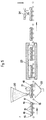
- FIGS. 1 and 2 show a panel 1 in the finished state and produced by the method according to the invention.
- This panel consists of elementary solar cells 2 electrically interconnected by conductive tabs 3 and having at least two connections such as 4 for connection with the outside.
- the solar cells 2 are embedded in a layer 5 of transparent thermoplastic material.
- This layer is placed between two rigid waterproof sheets 6 and 7, at least one of which, the sheet 6, is made of a transparent material, for example glass, or of a transparent plastic or vitrocrystalline material.
- the two rigid sheets are made of glass.
- FIG. 3 An alternative embodiment of a panel manufactured by the method according to the invention is shown in FIG. 3.
- This variant consists in enclosing layer 5 between two flexible thermoplastic sheets 8 and 9 which can be welded respectively to the material of layer 5 and to rigid sheets.
- the sheets 8 and 9 can advantageously be made with the same material as the layer 5.
- thermoplastic material for layer 5 a synthetic resin such as plasticized polyvinyl butyral is chosen as the thermoplastic material for layer 5.
- a synthetic resin such as plasticized polyvinyl butyral is chosen as the thermoplastic material for layer 5.
- Such a resin is described in French patent publication 2 401 941.
- the plasticizers used are esters insoluble in water, of acids with several carboxylic groups or of alcohols with several hydroxyl groups.
- the plasticizers which can be used are, for example, derivatives of polyethylene glycols such as di- (ethyl-2-butyrate) of triethylene glycol, triethylene glycol dipelargonate, adipates such as dihexyl adipate, dibutoxyethyladipate, alkyl and aryl adipates as indicated in French patent application No. 78 32737 filed on November 21, 1978 in the name of the applicant, dibutyl sebaçate ...
- plasticizers which can be used with polyvinyl butyral resin is not limiting. Those skilled in the art will know how to select the most suitable plasticizer from all known products.
- the solar cells can be made of monocrystalline or polycrystalline silicon, cadmium telluride, cadmium sulfide, gallium poly or monocrystalline arsenide, indium phosphide, etc.
- the connection and output tabs are for example tinned copper, silver, aluminum, their alloys or any other metallic compound having good electrical conductivity.
- Watertight panels have been produced by the applicant using two sheets of glass 3 mm thick, polyvinyl butyral resin as described in the publication FR 2 401 941 already mentioned, a plasticizer, silicon solar cells in the form of discs 0.3 mm thick and 57 mm in diameter.
- the connections are made of tinned copper.
- a uniform layer of a mixture of polyvinyl butyral resin powders and plasticizer constituted by triethylene glycol di- (ethyl-2-butyrate) at a rate of 41 is distributed through a sieve. parts by weight of plasticizer per 100 parts by weight of resin.
- This mixture was prepared beforehand in a planetary mixer, of the kneading type, at room temperature.
- the apparent density of the mixture is 0.2 g / cm.
- the thickness of the layer of plasticized resin deposited on the glass sheet is 5 mm.
- the interconnected cells of the panel are placed on the plasticized powder layer using a pneumatic sampling system comprising a suction cup for each cell.
- a new layer of plasticized resin identical to the previous one is then distributed on the previous laminate.
- the layer is as uniform as possible and 5 mm thick.
- a 3 mm glass plate is placed above the last layer.
- the sandwich thus obtained is then slipped into a flexible bag 10, for example made of rubber, in which a vacuum can be produced using a tube 11 connected to a vacuum pump not shown, in order to eliminate the occluded gases. .
- the bag is placed in an autoclave 12.
- the vacuum is produced in the bag at room temperature for about half an hour, then a pressure of 2 bars is applied to the outside of the bag by admitting compressed air into the autoclave.
- the vacuum is always maintained inside the bag.
- the assembly is maintained under 10 bars and 140 ° C for 30 minutes, time after which the assembly is gradually cooled under pressure.
- the autoclave is decompressed, the vacuum is broken and the panel is recovered.
- the solar cell panel does not show any bubbles or heterogeneities by transparency.
- a panel similar to that of Example 1 is produced with a content of triethyleneglycol di- (ethyl-2-butyrate) plasticizer of 20 parts by weight per 100 parts by weight of resin.
- the maximum temperature reached in the autoclave is 150 ° C.
- the panel obtained is free of bubbles or heterogeneities.
- a panel is produced in the manner described in Example 1 except that the plasticizer is benzyl and octyl adipate in an amount of 34 parts by weight per 100 parts by weight of resin.
- the panel obtained has neither bubbles nor heterogeneities.
- the interconnected silicon photoelectric cells are deposited with the same device as in Example 1, then a mixture of polyvinyl butyral resin powders and plasticizer is dropped on it, through a sieve.
- a glass sheet is placed on the layer of polyvinyl butyral resin.
- the assembly is then placed in a flexible bag and treated in an autoclave as in Example 1.
- the panel seen by transparency, has neither bubbles nor heterogeneities.
- One of the transparent rigid sheets is covered with a layer of a mixture in the form of a powder of thermoplastic coating material and of plasticizer, then the interconnected photocells are deposited and pressed into this layer until their upper surface arrives below the level of the upper surface of the layer.
- the second transparent rigid sheet is then placed directly on the solar cells without adding a second layer of thermoplastic coating material and plasticizer. Under the action of its own weight and low pressure, the second sheet crushes the mounds of powder projecting between the solar cells and spreads them out to form a layer of constant thickness.
- a panel with improved sealing is produced from a panel produced according to one of examples 1 to 4. At the periphery of the panel the four sides are covered with a mold and a pressure is injected into this mold.
- silicone resin known under the brand name "RTV” from Rhône Poulenc. In the example considered, this mold is made of polymethyl methacrylate. After polymerization of the silicone resin in the mold, the seal formed covers the edge of the panel.
- the invention also contemplates the use of various additives in the plasticized polyvinyl butyral powder.
- additives include stabilizers, anti-ultraviolet, adhesion modifiers, etc.
- a sheet of polyvinyl butyral 0.5 mm thick plasticized with 41 parts by weight of triethylene glycol di- (ethyl-2-butyrate) per 100 parts by weight of resin is placed on a first glass sheet.
- the solar cells are placed on this sheet of polyvinyl butyral.
- a layer of plasticized polyvinyl butyral powder is spread between the solar cells and on them like the previous sheet.
- a plasticized polyvinyl butyral sheet is placed on the powder layer like the first sheet and has the same thickness of 0.5 mm.
- a sheet of glass is placed on this second sheet.
- the panel thus prepared is sheathed in a flexible bag and the whole carried in an autoclave where it is treated as described in Example 1.
- said solar cell panel After extraction of the autoclave panel and the bag, said solar cell panel exhibits, by transparency, neither bubbles nor heterogeneities.
- a polyvinyl butyral film is deposited, then interconnected solar cells with a thickness of 0.8 mm. On each of these, a cover is deposited which can be easily removed after the polyvinyl butyral powder has been put in place.
- the pneumatic collection system of the solar cells described in Example 1 can be left in place on them during the spreading of the polyvinyl butyral powder if such a system allows this spreading and can be removed without disturbing the layer.
- Tests have also been carried out by placing on the upper face of each solar cell a cover made up of an aluminum disc approximately 1.5 mm thick, and with the same surface area as that of the solar cell. Each disc has a more or less vertical rod of a height sufficient to exceed the height that will present, after its installation, the layer of polyvinyl butyral above the upper face of the solar cells. After putting this layer in place, all of the covers are removed by means of their rods by any suitable means.
- Example 1 After depositing the powder between the cells and on the covers and removing the latter, a new layer of polyvinyl butyral powder is placed which covers the cells. Then, the rigid and transparent sheet such as in glass is placed.
- the panel thus prepared is, as in Example 1, introduced into a flexible bag connected to the vacuum, the whole being carried in an autoclave to undergo the heat bonding treatment under pressure.
- a preform in sintered powder in order to avoid variations in the thickness of the layer of thermoplastic resin powder, a preform in sintered powder.
- the preform is produced by means of a mold 15 in the form of a flat bowl, open at the top.
- the mold has a flat bottom on which can be fixed or come from manufacturing, in locations corresponding to those of the solar cells in the array to be coated, rigid elements 16 of the same shape and of dimensions approximately equal to cells of the solar cells.
- the side walls 17 of the mold are orthogonal to the bottom and end at their upper edge by sharp edges 18, all located in the same plane parallel to that of the bottom.
- the mold cavity is covered with a suitable non-stick coating.
- the mold 15 is deposited, cavity turned upwards, on a conveyor, such as a horizontal roller conveyor 19, which conveys it to a distributor 20 of thermoplastic resin in the powder state.
- a conveyor such as a horizontal roller conveyor 19
- Polyvinyl butyral resin plasticized with benzyl and octyl adipate is used, in an amount of 34 parts by weight of plasticizer per 100 parts by weight of resin.
- the mold is driven at a speed of 0.4 meters per minute under the dispenser which delivers the plasticized powder at the rate of 1000 grams per square meter.
- the mold, filled with an excess of powder, is then directed by the conveyor to a station comprising a smooth calendering cylinder 21, rotating around a controlled horizontal axis.
- the cylinder is adjusted in height so as to be flush with the sharp edges 18 of the mold, so that as the mold runs under the cylinder, the excess powder is removed and the upper face of the preform is made flat. In addition, the edges of the preform are clearly cut at the sharp edges 18.
- the excess powder is collected in a collecting container 22.
- the transporter then introduces the filled mold into a tunnel oven 23 heated to a temperature of 50 ° C.
- the sintering of the plasticized polyvinyl butyral is obtained after a stay of 10 minutes from the mold in the oven.
- the preform 24 of sintered powder is removed from the mold, one of the faces of which has imprints 25 ready to receive the 0.3 mm thick solar cells, preconnected.
- the height of the preform can be approximately 5 mm and that of the imprints 1.5 mm.
- the preform 24 is then placed on the lower rigid sheet, the imprints facing upwards, and then the network of interconnected photocells is introduced into the imprints.
- this assembly with a sheet of polyvinyl butyral plasticized in the same proportions with adipate- benzyl and actyl with a thickness of about 0.5 mm.
- the assembly is then covered with the upper rigid sheet and the sandwich obtained is treated under the same conditions as in Example 1.
- a panel of solar cells free of bubbles and heterogeneities is obtained.
- the array of photocells is covered, deposited on a first layer of plasticized polyvinyl butyral powder applied to the bottom of the mold cavity, with a second layer of plasticized powder, the surface of which is smoothed and then the mold in the tunnel oven heated to 50 ° C, the residence time in the oven being 15 minutes.
- a 10 mm thick sintered preform is thus obtained coating the array of solar cells.
- the panel is completed by assembly between two sheets, the upper sheet being constituted by film glass 0.3 mm thick.
- Example 10 The procedure is as in Example 10, but using unplasticized polyvinyl butyral powder which is preformed and which is introduced for 15 minutes into the tunnel oven heated to a temperature of 170 ° C.
- the preform obtained is assembled with the other elements of the solar panel as in the previous examples.
- the array of solar cells is interconnected between a flat preform and a preform provided with a single peripheral imprint, fitting around all of the solar cells.
- Example 10 The procedure of Example 10 is reproduced except that rigid plates of acrylic polymer are used in place of glass plates for the manufacture of the sandwich.
- the purpose of the tempered glass sheets, which can easily be separated from the finished panel, is to prevent possible deformation of the acrylic plates during the passage of the sandwich in an autoclave.
- Example 10 is reproduced using, as a lower rigid plate, an aluminum or aluminum alloy plate with a minimum thickness of 3 millimeters.
Landscapes
- Photovoltaic Devices (AREA)
Claims (12)
Priority Applications (1)
| Application Number | Priority Date | Filing Date | Title |
|---|---|---|---|
| AT80400619T ATE6007T1 (de) | 1979-05-08 | 1980-05-07 | Verfahren zur herstellung von solarzellenpaneelen und durch dieses verfahren erhaltene paneele. |
Applications Claiming Priority (4)
| Application Number | Priority Date | Filing Date | Title |
|---|---|---|---|
| FR7911631 | 1979-05-08 | ||
| FR7911631A FR2456392A1 (fr) | 1979-05-08 | 1979-05-08 | Procede de fabrication de panneaux de photopiles solaires et panneaux obtenus par ce procede |
| FR8006568A FR2479570A2 (fr) | 1980-03-25 | 1980-03-25 | Procede de fabrication de panneaux de photopiles solaires et panneaux obtenus par ce procede |
| FR8006568 | 1980-03-25 |
Publications (4)
| Publication Number | Publication Date |
|---|---|
| EP0018924A2 EP0018924A2 (de) | 1980-11-12 |
| EP0018924A3 EP0018924A3 (en) | 1981-03-25 |
| EP0018924B1 true EP0018924B1 (de) | 1984-01-25 |
| EP0018924B2 EP0018924B2 (de) | 1989-01-04 |
Family
ID=26221146
Family Applications (1)
| Application Number | Title | Priority Date | Filing Date |
|---|---|---|---|
| EP80400619A Expired EP0018924B2 (de) | 1979-05-08 | 1980-05-07 | Verfahren zur Herstellung von Solarzellenpaneelen und durch dieses Verfahren erhaltene Paneele |
Country Status (7)
| Country | Link |
|---|---|
| US (1) | US4321418A (de) |
| EP (1) | EP0018924B2 (de) |
| AU (1) | AU537425B2 (de) |
| CA (1) | CA1159132A (de) |
| DE (1) | DE3066247D1 (de) |
| ES (1) | ES8100843A1 (de) |
| YU (1) | YU121680A (de) |
Families Citing this family (75)
| Publication number | Priority date | Publication date | Assignee | Title |
|---|---|---|---|---|
| US4383129A (en) * | 1980-06-11 | 1983-05-10 | California Institute Of Technology | Solar cell encapsulation |
| FR2501213A1 (fr) * | 1981-03-05 | 1982-09-10 | Altulor Sa | Prepolymere acrylique et son application a l'encapsulation de photopiles |
| FR2515874A1 (fr) * | 1981-11-05 | 1983-05-06 | Comp Generale Electricite | Procede d'encapsulation plastique de cellules solaires |
| DE3239676A1 (de) * | 1982-10-27 | 1984-05-03 | Licentia Patent-Verwaltungs-Gmbh, 6000 Frankfurt | Verfahren zur herstellung von solargeneratoren |
| US4681718A (en) * | 1984-05-09 | 1987-07-21 | Hughes Aircraft Company | Method of fabricating composite or encapsulated articles |
| DE3538986C3 (de) * | 1985-11-02 | 1994-11-24 | Deutsche Aerospace | Verfahren zur Herstellung eines Solargenerators |
| US4692557A (en) * | 1986-10-16 | 1987-09-08 | Shell Oil Company | Encapsulated solar cell assemblage and method of making |
| US5086003A (en) * | 1989-07-31 | 1992-02-04 | Texas Instruments Incorporated | Method for applying an organic insulator to a solar array |
| US5475920A (en) * | 1990-08-01 | 1995-12-19 | Burns; Carmen D. | Method of assembling ultra high density integrated circuit packages |
| US5367766A (en) * | 1990-08-01 | 1994-11-29 | Staktek Corporation | Ultra high density integrated circuit packages method |
| WO1992003035A1 (en) * | 1990-08-01 | 1992-02-20 | Staktek Corporation | Ultra high density integrated circuit packages, method and apparatus |
| US5377077A (en) * | 1990-08-01 | 1994-12-27 | Staktek Corporation | Ultra high density integrated circuit packages method and apparatus |
| US5446620A (en) * | 1990-08-01 | 1995-08-29 | Staktek Corporation | Ultra high density integrated circuit packages |
| US5448450A (en) * | 1991-08-15 | 1995-09-05 | Staktek Corporation | Lead-on-chip integrated circuit apparatus |
| US5702985A (en) * | 1992-06-26 | 1997-12-30 | Staktek Corporation | Hermetically sealed ceramic integrated circuit heat dissipating package fabrication method |
| US5484959A (en) * | 1992-12-11 | 1996-01-16 | Staktek Corporation | High density lead-on-package fabrication method and apparatus |
| US6205654B1 (en) * | 1992-12-11 | 2001-03-27 | Staktek Group L.P. | Method of manufacturing a surface mount package |
| EP0605994A1 (de) * | 1993-01-08 | 1994-07-13 | Ford Motor Company | Verfahren zur Verkapselung von photovoltaischen Zellen in einem Glaslaminat |
| US5369056A (en) * | 1993-03-29 | 1994-11-29 | Staktek Corporation | Warp-resistent ultra-thin integrated circuit package fabrication method |
| US5644161A (en) * | 1993-03-29 | 1997-07-01 | Staktek Corporation | Ultra-high density warp-resistant memory module |
| US5801437A (en) * | 1993-03-29 | 1998-09-01 | Staktek Corporation | Three-dimensional warp-resistant integrated circuit module method and apparatus |
| US5325011A (en) * | 1993-06-09 | 1994-06-28 | The United States Of America As Represented By The Asecretary Of The Navy | Transducers and method for making same |
| DE4331425A1 (de) * | 1993-09-16 | 1995-03-23 | Bmc Solar Ind Gmbh | Solarmodul mit Lochplatte |
| US5508205A (en) * | 1994-03-29 | 1996-04-16 | Amoco/Enron Solar | Method of making and utilizing partially cured photovoltaic assemblies |
| US5588205A (en) * | 1995-01-24 | 1996-12-31 | Staktek Corporation | Method of manufacturing a high density integrated circuit module having complex electrical interconnect rails |
| JP2915327B2 (ja) * | 1995-07-19 | 1999-07-05 | キヤノン株式会社 | 太陽電池モジュール及びその製造方法 |
| US6025642A (en) * | 1995-08-17 | 2000-02-15 | Staktek Corporation | Ultra high density integrated circuit packages |
| US5945732A (en) | 1997-03-12 | 1999-08-31 | Staktek Corporation | Apparatus and method of manufacturing a warp resistant thermally conductive integrated circuit package |
| US6572387B2 (en) | 1999-09-24 | 2003-06-03 | Staktek Group, L.P. | Flexible circuit connector for stacked chip module |
| JP2001291881A (ja) * | 2000-01-31 | 2001-10-19 | Sanyo Electric Co Ltd | 太陽電池モジュール |
| JP4036616B2 (ja) * | 2000-01-31 | 2008-01-23 | 三洋電機株式会社 | 太陽電池モジュール |
| US6608763B1 (en) | 2000-09-15 | 2003-08-19 | Staktek Group L.P. | Stacking system and method |
| US6462408B1 (en) | 2001-03-27 | 2002-10-08 | Staktek Group, L.P. | Contact member stacking system and method |
| US20050022857A1 (en) * | 2003-08-01 | 2005-02-03 | Daroczi Shandor G. | Solar cell interconnect structure |
| CN1879225A (zh) * | 2003-11-12 | 2006-12-13 | 安东尼·莫拉利 | 太阳能栏杆或围栏系统 |
| JP4359308B2 (ja) * | 2004-04-28 | 2009-11-04 | 中島硝子工業株式会社 | 太陽電池モジュールの製造方法 |
| DE102004030411A1 (de) * | 2004-06-23 | 2006-01-19 | Kuraray Specialities Europe Gmbh | Solarmodul als Verbundsicherheitsglas |
| WO2007112452A2 (en) * | 2006-03-28 | 2007-10-04 | Solopower, Inc. | Technique for manufacturing photovoltaic modules |
| US8148627B2 (en) * | 2006-08-25 | 2012-04-03 | Sunpower Corporation | Solar cell interconnect with multiple current paths |
| US20080128018A1 (en) * | 2006-12-04 | 2008-06-05 | Richard Allen Hayes | Solar cells which include the use of certain poly(vinyl butyral)/film bilayer encapsulant layers with a low blocking tendency and a simplified process to produce thereof |
| US8197928B2 (en) | 2006-12-29 | 2012-06-12 | E. I. Du Pont De Nemours And Company | Intrusion resistant safety glazings and solar cell modules |
| US8350417B1 (en) | 2007-01-30 | 2013-01-08 | Sunpower Corporation | Method and apparatus for monitoring energy consumption of a customer structure |
| DE102007005845A1 (de) | 2007-02-01 | 2008-08-07 | Kuraray Europe Gmbh | Verfahren zur Herstellung von Solarmodulen im Walzenverbundverfahren |
| US7943845B2 (en) * | 2007-02-07 | 2011-05-17 | E. I. Du Pont De Nemours And Company | Solar cells encapsulated with poly(vinyl butyral) |
| US8158877B2 (en) | 2007-03-30 | 2012-04-17 | Sunpower Corporation | Localized power point optimizer for solar cell installations |
| US7838062B2 (en) * | 2007-05-29 | 2010-11-23 | Sunpower Corporation | Array of small contacts for solar cell fabrication |
| DE102007000818A1 (de) | 2007-10-05 | 2009-04-09 | Kuraray Europe Gmbh | Photovoltaikmodule mit weichmacherhaltigen Folien geringer Feuchtigkeitsaufnahme |
| DE102007000816A1 (de) * | 2007-10-05 | 2009-04-09 | Kuraray Europe Gmbh | Photovoltaikmodule mit weichmacherhaltigen Folien auf Basis von Polyvinylacetal mit hohem spezifischen Widerstand |
| DE102007000817A1 (de) | 2007-10-05 | 2009-04-09 | Kuraray Europe Gmbh | Weichmacherhaltige Folien auf Basis von Polyvinylacetal mit erhöhter Glasübergangstemperatur und verbessertem Fließverhalten |
| DE102007055733A1 (de) | 2007-12-07 | 2009-06-10 | Kuraray Europe Gmbh | Photovoltaikmodule mit reflektierenden Klebefolien |
| JP5003670B2 (ja) * | 2007-12-27 | 2012-08-15 | 大成建設株式会社 | 建物の外被構造 |
| CN102832281A (zh) * | 2008-04-04 | 2012-12-19 | 纳幕尔杜邦公司 | 包含高熔体流动速率的聚(乙烯醇缩丁醛)包封材料的太阳能电池模块 |
| DE102008001505A1 (de) | 2008-04-30 | 2009-11-05 | Kuraray Europe Gmbh | Photovoltaikmodule enthaltend plastifizierte Zwischenschicht-Folien mit niedrigem Polyvinylacetatgehalt |
| DE102008001502A1 (de) | 2008-04-30 | 2009-11-05 | Kuraray Europe Gmbh | Photovoltaikmodule mit Kieselsäure-haltigen plastifizierten Zwischenschicht-Folien |
| DE102008001507A1 (de) | 2008-04-30 | 2009-11-05 | Kuraray Europe Gmbh | Photovoltaikmodule enthaltend plastifizierte Zwischenschicht-Folien mit hohem Alkalititer |
| DE102008001512A1 (de) | 2008-04-30 | 2009-11-05 | Kuraray Europe Gmbh | Dünnschicht-Solarmodul als Verbundsicherheitsglas |
| DE102008042218A1 (de) | 2008-04-30 | 2009-11-05 | Kuraray Europe Gmbh | Photovoltaikmodule enthaltend plastifizierte Zwischenschicht-Folien mit niedriger Glasübergangstemperatur |
| DE102008001654A1 (de) | 2008-05-08 | 2009-11-12 | Kuraray Europe Gmbh | Photovoltaikmodule enthaltend plastifizierte Zwischenschicht-Folien mit hohem Durchgangswiderstand und guter Penetrationsfestigkeit |
| DE102008001684A1 (de) | 2008-05-09 | 2009-11-12 | Kuraray Europe Gmbh | Verfahren zur Herstellung von Photovoltaikmodulen im Vakuumlaminator mit reduziertem Prozessvakuum |
| US20090288701A1 (en) * | 2008-05-23 | 2009-11-26 | E.I.Du Pont De Nemours And Company | Solar cell laminates having colored multi-layer encapsulant sheets |
| JP2011522419A (ja) * | 2008-05-27 | 2011-07-28 | ソルティア・インコーポレーテッド | 薄膜光起電モジュール |
| DE102009014348A1 (de) * | 2008-06-12 | 2009-12-17 | Bayer Materialscience Ag | Leichtes, biegesteifes und selbsttragendes Solarmodul sowie ein Verfahren zu dessen Herstellung |
| DE102008042882A1 (de) | 2008-10-16 | 2010-04-22 | Kuraray Europe Gmbh | Photovoltaikmodule enthaltend plastifizierte Zwischenschicht-Folien aus Polyvinylacetalen mit hohem Polyvinylacetatgehalt |
| JP5436901B2 (ja) * | 2009-03-23 | 2014-03-05 | 三洋電機株式会社 | 太陽電池モジュールの製造方法 |
| EP2259335A1 (de) | 2009-05-15 | 2010-12-08 | Kuraray Europe GmbH | Photovoltaikmodule enthaltend plastifizierte Zwischenschicht-Folien mit reduzierter Eigenklebrigkeit |
| EP2259334A1 (de) | 2009-06-05 | 2010-12-08 | Kuraray Europe GmbH | Photovoltaikmodule mit weichmacherhaltigen Folien geringer Kriechneigung |
| DE102009026026A1 (de) * | 2009-06-24 | 2010-12-30 | Malibu Gmbh & Co. Kg | Photovoltaikmodul und Verfahren zu dessen Herstellung |
| EP2425969A1 (de) | 2010-09-05 | 2012-03-07 | Kuraray Europe GmbH | Photovoltaikmodule mit mineralischen Füllstoff enthaltenden Klebefolien auf Basis Polyvinylacetal |
| US8426974B2 (en) | 2010-09-29 | 2013-04-23 | Sunpower Corporation | Interconnect for an optoelectronic device |
| US9029689B2 (en) | 2010-12-23 | 2015-05-12 | Sunpower Corporation | Method for connecting solar cells |
| CN103165708A (zh) * | 2011-12-09 | 2013-06-19 | 纳幕尔杜邦公司 | 用于光伏模块的可交联边缘密封剂 |
| CN105612056A (zh) * | 2013-10-15 | 2016-05-25 | 梅耶博格公司 | 用于形成层压板的方法和系统 |
| US9991405B2 (en) * | 2014-02-28 | 2018-06-05 | Sunpower Corporation | Solar module with aligning encapsulant |
| NL2012563B1 (en) * | 2014-04-03 | 2016-03-08 | Stichting Energieonderzoek Centrum Nederland | Solar cell module and method manufacturing such a module. |
| US10186628B2 (en) * | 2014-06-20 | 2019-01-22 | Vismunda Srl | Apparatus for the automatic horizontal assembly of photovoltaic panels |
Family Cites Families (10)
| Publication number | Priority date | Publication date | Assignee | Title |
|---|---|---|---|---|
| US2611930A (en) * | 1948-08-06 | 1952-09-30 | Westinghouse Electric Corp | Insulating electrical apparatus |
| US3653970A (en) * | 1969-04-30 | 1972-04-04 | Nasa | Method of coating solar cell with borosilicate glass and resultant product |
| US3912540A (en) * | 1971-06-21 | 1975-10-14 | Nasa | Covered silicon solar cells and method of manufacture |
| JPS5328751B2 (de) * | 1974-11-27 | 1978-08-16 | ||
| FR2349959A1 (fr) * | 1976-04-27 | 1977-11-25 | Radiotechnique Compelec | Procede de fabrication de panneaux de photopiles solaires et panneaux fabriques par ce procede |
| US4057439A (en) * | 1976-08-25 | 1977-11-08 | Solarex Corporation | Solar panel |
| US4083097A (en) * | 1976-11-30 | 1978-04-11 | The United States Of America As Represented By The Administrator Of The National Aeronautics And Space Administration | Method of making encapsulated solar cell modules |
| US4067764A (en) * | 1977-03-15 | 1978-01-10 | Sierracin Corporation | Method of manufacture of solar cell panel |
| FR2395609A1 (fr) * | 1977-06-24 | 1979-01-19 | Radiotechnique Compelec | Panneau generateur a cellules solaires noyees dans un stratifie et procede pour l'obtenir |
| US4116207A (en) * | 1977-07-12 | 1978-09-26 | Solarex Corporation | Solar panel with mat base member |
-
1980
- 1980-05-07 ES ES491243A patent/ES8100843A1/es not_active Expired
- 1980-05-07 DE DE8080400619T patent/DE3066247D1/de not_active Expired
- 1980-05-07 CA CA000351408A patent/CA1159132A/fr not_active Expired
- 1980-05-07 YU YU01216/80A patent/YU121680A/xx unknown
- 1980-05-07 EP EP80400619A patent/EP0018924B2/de not_active Expired
- 1980-05-08 US US06/147,921 patent/US4321418A/en not_active Expired - Lifetime
- 1980-05-08 AU AU58222/80A patent/AU537425B2/en not_active Ceased
Also Published As
| Publication number | Publication date |
|---|---|
| US4321418A (en) | 1982-03-23 |
| ES491243A0 (es) | 1980-12-16 |
| AU537425B2 (en) | 1984-06-21 |
| YU121680A (en) | 1983-04-30 |
| CA1159132A (fr) | 1983-12-20 |
| EP0018924A3 (en) | 1981-03-25 |
| EP0018924A2 (de) | 1980-11-12 |
| EP0018924B2 (de) | 1989-01-04 |
| ES8100843A1 (es) | 1980-12-16 |
| DE3066247D1 (en) | 1984-03-01 |
| AU5822280A (en) | 1980-11-13 |
Similar Documents
| Publication | Publication Date | Title |
|---|---|---|
| EP0018924B1 (de) | Verfahren zur Herstellung von Solarzellenpaneelen und durch dieses Verfahren erhaltene Paneele | |
| EP3776668B1 (de) | Leichtgewichtiges und flexibles photovoltaisches modul mit einer vorderen schicht aus einem polymer und einer hinteren schicht aus einem verbundwerkstoff | |
| EP3493277B1 (de) | Verfahren zur verbindung von photovoltaikzellen mit einer elektrode, ausgestattet mit metallnanodrähten | |
| WO1982003728A1 (fr) | Panneau de cellules solaires et son procede de fabrication | |
| EP1368174B1 (de) | Verfahren zur herstellung von verglasungen aus kunststoff | |
| EP4002491B1 (de) | Verbessertes leichtes und flexibles fotovoltaikmodul | |
| WO2017085017A1 (fr) | Module photovoltaïque léger comportant une couche avant en verre ou polymère et une couche arrière alvéolaire | |
| EP3859793B1 (de) | Leichtes fotovoltaikmodul mit einer vorderen und einer hinteren schicht aus verbundmaterialien | |
| FR3043841A1 (fr) | Module photovoltaique leger comportant une couche avant en verre ou polymere et une couche arriere en relief | |
| FR3107990A1 (fr) | Module photovoltaïque léger comportant des couches avant et arrière polymère et des renforts fibrés | |
| WO2023199005A1 (fr) | Module photovoltaïque léger comportant un cadre composite intégré | |
| JPH0139228B2 (de) | ||
| WO2024009035A1 (fr) | Procédé de fabrication d'un module photovoltaïque utilisant un moulage par transfert de résine | |
| FR2466865A1 (fr) | Procede de fabrication de panneaux de photopiles solaires, moyen permettant cette fabrication et panneaux fabriques par ce procede | |
| EP4463894A1 (de) | Verfahren zur herstellung eines fotovoltaischen moduls und entsprechende herstellungsanlage | |
| WO2023041864A1 (fr) | Module photovoltaïque léger comportant une couche avant en verre et polymère | |
| FR3001480A1 (fr) | Tuile photovoltaique sur substrat poreux | |
| EP4032131B1 (de) | Fotovoltaikmodul mit einem elektrisch leitenden verbindungselement | |
| KR830001696B1 (ko) | 태양 광전지 판넬의 제조방법 | |
| FR2491680A1 (fr) | Procede de fabrication de modules a piles solaires | |
| EP4732342A1 (de) | Verfahren zur herstellung eines photovoltaikmoduls durch thermoformen eines mehrschichtstapels | |
| FR2567448A1 (fr) | Distribution d'un elastomere a forte viscosite | |
| EP4511884A1 (de) | Leichtes, schlagfestes photovoltaisches modul | |
| FR3071682A1 (fr) | Procede de fabrication d'un module photovoltaique avec controle de la distance inter-series de cellules photovoltaiques |
Legal Events
| Date | Code | Title | Description |
|---|---|---|---|
| PUAI | Public reference made under article 153(3) epc to a published international application that has entered the european phase |
Free format text: ORIGINAL CODE: 0009012 |
|
| AK | Designated contracting states |
Designated state(s): AT BE CH DE GB IT LU NL |
|
| PUAL | Search report despatched |
Free format text: ORIGINAL CODE: 0009013 |
|
| AK | Designated contracting states |
Designated state(s): AT BE CH DE GB IT LU NL |
|
| 17P | Request for examination filed |
Effective date: 19810404 |
|
| ITF | It: translation for a ep patent filed | ||
| GRAA | (expected) grant |
Free format text: ORIGINAL CODE: 0009210 |
|
| AK | Designated contracting states |
Designated state(s): AT BE CH DE GB IT LI LU NL |
|
| REF | Corresponds to: |
Ref document number: 6007 Country of ref document: AT Date of ref document: 19840215 Kind code of ref document: T |
|
| REF | Corresponds to: |
Ref document number: 3066247 Country of ref document: DE Date of ref document: 19840301 |
|
| REG | Reference to a national code |
Ref country code: CH Ref legal event code: PFA Free format text: SAINT-GOBAIN VITRAGE |
|
| PLBI | Opposition filed |
Free format text: ORIGINAL CODE: 0009260 |
|
| 26 | Opposition filed |
Opponent name: SIEMENS AKTIENGESELLSCHAFT, BERLIN UND MUENCHEN Effective date: 19841025 |
|
| NLR1 | Nl: opposition has been filed with the epo |
Opponent name: SIEMENS AG |
|
| PUAH | Patent maintained in amended form |
Free format text: ORIGINAL CODE: 0009272 |
|
| STAA | Information on the status of an ep patent application or granted ep patent |
Free format text: STATUS: PATENT MAINTAINED AS AMENDED |
|
| 27A | Patent maintained in amended form |
Effective date: 19890104 |
|
| AK | Designated contracting states |
Kind code of ref document: B2 Designated state(s): AT BE CH DE GB IT LU NL |
|
| NLR2 | Nl: decision of opposition | ||
| ITF | It: translation for a ep patent filed | ||
| NLR3 | Nl: receipt of modified translations in the netherlands language after an opposition procedure | ||
| ITTA | It: last paid annual fee | ||
| PGFP | Annual fee paid to national office [announced via postgrant information from national office to epo] |
Ref country code: DE Payment date: 19920708 Year of fee payment: 13 |
|
| PGFP | Annual fee paid to national office [announced via postgrant information from national office to epo] |
Ref country code: AT Payment date: 19930413 Year of fee payment: 14 |
|
| PGFP | Annual fee paid to national office [announced via postgrant information from national office to epo] |
Ref country code: CH Payment date: 19930527 Year of fee payment: 14 |
|
| PGFP | Annual fee paid to national office [announced via postgrant information from national office to epo] |
Ref country code: NL Payment date: 19930531 Year of fee payment: 14 |
|
| PG25 | Lapsed in a contracting state [announced via postgrant information from national office to epo] |
Ref country code: DE Effective date: 19940201 |
|
| PGFP | Annual fee paid to national office [announced via postgrant information from national office to epo] |
Ref country code: BE Payment date: 19940331 Year of fee payment: 15 |
|
| PGFP | Annual fee paid to national office [announced via postgrant information from national office to epo] |
Ref country code: GB Payment date: 19940420 Year of fee payment: 15 |
|
| PGFP | Annual fee paid to national office [announced via postgrant information from national office to epo] |
Ref country code: LU Payment date: 19940430 Year of fee payment: 15 |
|
| PG25 | Lapsed in a contracting state [announced via postgrant information from national office to epo] |
Ref country code: AT Effective date: 19940507 |
|
| PG25 | Lapsed in a contracting state [announced via postgrant information from national office to epo] |
Ref country code: LI Effective date: 19940531 Ref country code: CH Effective date: 19940531 |
|
| EPTA | Lu: last paid annual fee | ||
| PG25 | Lapsed in a contracting state [announced via postgrant information from national office to epo] |
Ref country code: NL Effective date: 19941201 |
|
| NLV4 | Nl: lapsed or anulled due to non-payment of the annual fee | ||
| REG | Reference to a national code |
Ref country code: CH Ref legal event code: PL |
|
| PG25 | Lapsed in a contracting state [announced via postgrant information from national office to epo] |
Ref country code: LU Free format text: LAPSE BECAUSE OF NON-PAYMENT OF DUE FEES Effective date: 19950507 Ref country code: GB Effective date: 19950507 |
|
| PG25 | Lapsed in a contracting state [announced via postgrant information from national office to epo] |
Ref country code: BE Effective date: 19950531 |
|
| BERE | Be: lapsed |
Owner name: SAINT-GOBAIN VITRAGE Effective date: 19950531 |
|
| GBPC | Gb: european patent ceased through non-payment of renewal fee |
Effective date: 19950507 |
|
| APAH | Appeal reference modified |
Free format text: ORIGINAL CODE: EPIDOSCREFNO |