EP0012213A1 - Système d'injection pour un moteur à combustion interne - Google Patents
Système d'injection pour un moteur à combustion interne Download PDFInfo
- Publication number
- EP0012213A1 EP0012213A1 EP79104293A EP79104293A EP0012213A1 EP 0012213 A1 EP0012213 A1 EP 0012213A1 EP 79104293 A EP79104293 A EP 79104293A EP 79104293 A EP79104293 A EP 79104293A EP 0012213 A1 EP0012213 A1 EP 0012213A1
- Authority
- EP
- European Patent Office
- Prior art keywords
- fuel
- passage
- tubular element
- air
- porous tubular
- Prior art date
- Legal status (The legal status is an assumption and is not a legal conclusion. Google has not performed a legal analysis and makes no representation as to the accuracy of the status listed.)
- Granted
Links
- 239000000446 fuel Substances 0.000 title claims abstract description 193
- 238000002347 injection Methods 0.000 title claims abstract description 39
- 239000007924 injection Substances 0.000 title claims abstract description 39
- 238000002485 combustion reaction Methods 0.000 title claims description 10
- 239000000203 mixture Substances 0.000 claims abstract description 34
- 230000002093 peripheral effect Effects 0.000 claims description 20
- 238000005192 partition Methods 0.000 claims description 4
- 239000000919 ceramic Substances 0.000 claims description 3
- 238000011144 upstream manufacturing Methods 0.000 claims description 3
- 239000002184 metal Substances 0.000 claims description 2
- 239000004033 plastic Substances 0.000 claims description 2
- 239000008240 homogeneous mixture Substances 0.000 abstract description 2
- 239000010419 fine particle Substances 0.000 abstract 1
- 239000002245 particle Substances 0.000 description 27
- 235000014676 Phragmites communis Nutrition 0.000 description 7
- 238000000889 atomisation Methods 0.000 description 6
- 239000011148 porous material Substances 0.000 description 6
- 230000000694 effects Effects 0.000 description 4
- 230000007246 mechanism Effects 0.000 description 3
- 230000010349 pulsation Effects 0.000 description 3
- 239000004020 conductor Substances 0.000 description 2
- 230000003247 decreasing effect Effects 0.000 description 2
- 230000000977 initiatory effect Effects 0.000 description 2
- 230000002776 aggregation Effects 0.000 description 1
- 238000004220 aggregation Methods 0.000 description 1
- 230000008901 benefit Effects 0.000 description 1
- 238000010276 construction Methods 0.000 description 1
- 238000002474 experimental method Methods 0.000 description 1
- 239000010687 lubricating oil Substances 0.000 description 1
- 238000004519 manufacturing process Methods 0.000 description 1
- 239000003921 oil Substances 0.000 description 1
- 230000002035 prolonged effect Effects 0.000 description 1
- 230000009467 reduction Effects 0.000 description 1
- 238000000926 separation method Methods 0.000 description 1
Images


Classifications
-
- F—MECHANICAL ENGINEERING; LIGHTING; HEATING; WEAPONS; BLASTING
- F02—COMBUSTION ENGINES; HOT-GAS OR COMBUSTION-PRODUCT ENGINE PLANTS
- F02M—SUPPLYING COMBUSTION ENGINES IN GENERAL WITH COMBUSTIBLE MIXTURES OR CONSTITUENTS THEREOF
- F02M69/00—Low-pressure fuel-injection apparatus ; Apparatus with both continuous and intermittent injection; Apparatus injecting different types of fuel
- F02M69/04—Injectors peculiar thereto
- F02M69/047—Injectors peculiar thereto injectors with air chambers, e.g. communicating with atmosphere for aerating the nozzles
-
- F—MECHANICAL ENGINEERING; LIGHTING; HEATING; WEAPONS; BLASTING
- F02—COMBUSTION ENGINES; HOT-GAS OR COMBUSTION-PRODUCT ENGINE PLANTS
- F02M—SUPPLYING COMBUSTION ENGINES IN GENERAL WITH COMBUSTIBLE MIXTURES OR CONSTITUENTS THEREOF
- F02M69/00—Low-pressure fuel-injection apparatus ; Apparatus with both continuous and intermittent injection; Apparatus injecting different types of fuel
- F02M69/08—Low-pressure fuel-injection apparatus ; Apparatus with both continuous and intermittent injection; Apparatus injecting different types of fuel characterised by the fuel being carried by compressed air into main stream of combustion-air
-
- F—MECHANICAL ENGINEERING; LIGHTING; HEATING; WEAPONS; BLASTING
- F02—COMBUSTION ENGINES; HOT-GAS OR COMBUSTION-PRODUCT ENGINE PLANTS
- F02M—SUPPLYING COMBUSTION ENGINES IN GENERAL WITH COMBUSTIBLE MIXTURES OR CONSTITUENTS THEREOF
- F02M7/00—Carburettors with means for influencing, e.g. enriching or keeping constant, fuel/air ratio of charge under varying conditions
-
- F—MECHANICAL ENGINEERING; LIGHTING; HEATING; WEAPONS; BLASTING
- F02—COMBUSTION ENGINES; HOT-GAS OR COMBUSTION-PRODUCT ENGINE PLANTS
- F02M—SUPPLYING COMBUSTION ENGINES IN GENERAL WITH COMBUSTIBLE MIXTURES OR CONSTITUENTS THEREOF
- F02M71/00—Combinations of carburettors and low-pressure fuel-injection apparatus
-
- Y—GENERAL TAGGING OF NEW TECHNOLOGICAL DEVELOPMENTS; GENERAL TAGGING OF CROSS-SECTIONAL TECHNOLOGIES SPANNING OVER SEVERAL SECTIONS OF THE IPC; TECHNICAL SUBJECTS COVERED BY FORMER USPC CROSS-REFERENCE ART COLLECTIONS [XRACs] AND DIGESTS
- Y10—TECHNICAL SUBJECTS COVERED BY FORMER USPC
- Y10S—TECHNICAL SUBJECTS COVERED BY FORMER USPC CROSS-REFERENCE ART COLLECTIONS [XRACs] AND DIGESTS
- Y10S261/00—Gas and liquid contact apparatus
- Y10S261/39—Liquid feeding nozzles
Definitions
- the present invention relates to a fuel injection system for supplying a fuel to an internal combustion engine and, more particularly, to a fuel control device for a fuel injection system of the type that injects a fuel intermittently.
- This type of fuel injection systems is operative to produce pulse signals according to the operating condition of an associated internal combustion engine and to deliver these signals to an electromagnetic fuel injector so that the internal combustion engine is supplied with the fuel intermittently in synchronization with the engine operation.
- the intermittent fuel injection systems are sorted into two types, one is the Single Point Injection type and the other is the Multi-point Injection system.
- the single point injection system has a single injector adapted for supplying the fuel to all or a half of the cylinders of the internal combustion engine, whereas the multi-point injection system is adapted to supply the fuel to the cylinders by means of injectors associated with respective engine cylinders.
- valve-open period of the fuel injector is set to be 2 ms, for example, at an idling speed of 600 R.P.M.
- the valve-open period will be prolonged to 10 ms, which is longer than the valve-open period of the intake valves, as the engine speed is increased to 3,000 R.P.M.
- the valve-open period of the injector be determined on the basis of the engine speed at the high-speed engine operation. This, however, causes an unsteady idling operation, because the fuel injection interval is inconveniently increased during the idling operation.
- valve-open period of the fuel injector is selected to be 5 ms at 3,000 R.P.M.
- the valve-open period will be shortened to 1 ms as the engine speed is decreased to the idling speed of 600 R.P.M.
- This valve-open period is too short for the valve-opening period of the intake valves during the idling operation which is typically 50 ms. Under such a condition, there is a considerably long period in which air is supplied solely, after each fuel injection, so that the whole intake air is not mixed with the fuel homogeneously to make the idle operation unsteady.
- the fuel injected from the fuel injector is atomized into fuel particles of particle sizes as small as possible; because the smaller particle size ensures a better driveability and emission control, as well as reduced fuel consumption rate.
- the particle size of the fuel particles injected from conventional fuel injectors is around 300 p which cannot be considered sufficiently small. Therefore, part of the fuel taken into the engine attaches to the wall of the cylinder and is emitted from the latter before it is burnt. The fuel attaching to the cylinder wall, on the other hand, dilutes the lubricating oil and increases the fuel consumption rate uneconomically.
- this system can atomize the fuel only to the order of 50 to 70 p , which is considered still insufficient, particularly in view of current social concern about the exhaustion of oil resources.
- an object of the present invention to provide a fuel control device for a fuel injection system, capable of ensuring a steady and smooth engine operation particularly during the idling.
- a fuel control device for a fuel injection system having a tubular member made of a porous material and opened at its both ends.
- the porous tubular member has one end disposed near the fuel discharge orifice of a fuel injector, such that most part of the fuel discharged from the discharge orifice attaches to the inner peripheral surface of the porous tubular member.
- means are provided for supplying air from the outside to the inside of the porous tubular member through the pores of the wall of the latter, so that the fuel flowing through the porous tubular member is sufficiently mixed with the air.
- Fig. 1 shows a single point fuel injection system incorporating a fuel control device which is an embodiment of the invention.
- a throttle body denoted by a reference numeral 10 has an intake passage 12 formed therein.
- the intake passage 12 is divided into two passage sections by a partition 62. 0ne of these two passage sections is a primary passage 14, while the other is a secondary passage 16.
- the primary and the secondary passages 14 and 16 are provided with a primary throttle valve 18 and a secondary throttle valve-20, respectively.
- These throttle valves 18, 20 are operatively connected by a suitable connecting mechanism such that the secondary throttle valve 20 starts to open only after the primary throttle valve 18 has been opened to a predetermined opening.
- a mechanism similar to that of a known multi-stage carburetor can be used as this connecting mechanism.
- a fuel injector 22 is fixed to the throttle body 10 through the medium of a rubber seal 24, and is adapted to be supplied with a fuel delivered by a fuel pump (not shown) through a pipe 26.
- the fuel injector 22 receives also an electric signal which is derived from a control unit (not shown) through electric conductors 28.
- a tubular element 32 made of a porous material is disposed in the vicinity of a discharge orifice 30 of the fuel injector 30.
- the fuel injected from the fuel injector 22 is supplied to a portion of the primary passage 14 downstream from the primary throttle valve 18, through this tubular element 32.
- An air passage 34 is provided for supplying air to the outer periphery of the porous tubular element 32.
- the fuel injector 22 is adapted to be mounted in a first bore 36 formed in the wall of the throttle body 10.
- the first bore 36 is in communication with a second bore 38.
- the porous tubular element is a hollow tubular member opened at its both ends and is fixed to the inside of the first bore 36 through the medium of "0" rings 40.
- the annular space 42 defined by the "0" rings, inner peripheral surface of the first bore 36 and the outer peripheral surface of the porous tubular element 32 is communicated with the aforementioned air passage 34.
- the porous tubular element 32 is made of a sintered metal or a porous plastic having a good anti- gasoline characteristic. A multiplicity of minute passages are formed by pores across the thickness of the wall of the porous tubular element 32 so that the air supplied to the space 42 is made to flow through these minute passages into a mixture passage 44 defined in the porous tubular element 32.
- the porous tubular element 32 is disposed in close contact with the fuel injector 22 so that the discharge orifice 30 of the latter opens directly to the mixture passage 44.
- the air is allowed to flow into the mixture passage 44 only through the minute air passage formed through the wall of the porous tubular element 32 across the thickness of the latter. If there is any passage bypassing the minute passages formed in the porous tubular element 32, the flow rate of the air flowing through these minute passages will be decreased drastically.
- porous tubular element 32 The operation of the porous tubular element 32 will be described hereinunder with specific reference to Fig. 3.
- the latter injects the fuel F through its discharge orifice 30.
- the flow of the fuel F discharged through the discharge orifice 30 diverges radially outwardly to collide with the inner peripheral surface of the mixture passage 44 and the fuel F adheres to that wall.
- this adherence of the fuel to the inner peripheral wall of the mixture passage 44 constitutes one of the important features of the invention.
- the fuel F adhering to the inner peripheral surface of the mixture passage 44 then flows on that surface and is instantaneously atmized into fine fuel particles by the air which is blown into the mixture passage 44 through the minute passages formed through the wall of the porous tubular element 32.
- the fine fuel particles B then flow through the mixture passage 44 and are induced into-the engine.
- valve-open period of the fuel injector is much shorter than that of the intake valves during idle operation of the engine, so that air is solely supplied over a considerably long period after a short period of the fuel injection from the fuel injector, resulting in a heterogeneous mixing of the total intake air.
- the fuel is prevented from being supplied into the engine in a short period of time, by making an efficient use of fuel adherence characteristic of the porous material of the tubular element constituting the mixture passage 44.
- the fuel adhering characteristic of the porous material most part of the fuel discharged from the fuel injector 22 is made to adhere to the inner peripheral surface of the mixture passage so that it is prevented from flowing into the engine immediately after the injection.
- the problem attributable to the adherence of the fuel to the inner peripheral surface of the mixture passage 44 i.e.
- the growth or coarsening of the fuel particles is fairly overcome by the air which is supplied into the mixture passage 44 through the minute air passages formed across the wall thickness of the porous tubular element 32, because this air effectively atomizes the fuel into sufficiently small fuel particles to permit a homogeneous mixing of the total intake air with the fuel.
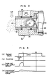
- Fig. 4 is a time chart showing the valve-open periods of the intake valve and the fuel injector, as well as the period of the fuel supply during the idle operation of the engine. More specifically, charts (a) and (b) show the valve-open periods of the intake valve and the fuel injector, respectively, while charts (c) and (d) show the periods of fuel supply by a conventional fuel injector and a fuel injector of the invention, respectively.
- a signal for initiating the fuel injection is delivered to the fuel injector, so that the latter opens as shown in the chart (b) to inject the fuel.
- the total of a charge of fuel is fed into the engine in quite a short period of time as shown in the chart (c). Therefore, after the fuel supply by the fuel injector is ceased, air is solely supplied until the intake valve is closed, so that the total intake air is not mixed with the fuel homogeneously. More specifically, in the conventional fuel injection system, the fuel is mixed only with a part of the intake air which is introduced during a short period between the moment at which the fuel injection is started and a moment "L" shown in the chart (a).
- the fuel is not supplied in short period of time, in the fuel injection system having the fuel control device of the invention. Rather, the fuel is supplied to the engine over almost whole period of opening of the intake valve. It is, therefore, possible to obtain a homogeneous mixing of the total intake air with the fuel. It will be seen that, according to the invention, the fuel and air supplied during idling are mixed homogeneously with each other to provide a steady and smooth idle operation of the engine.
- the fuel is made to flow on the inner peripheral surface of the mixture passage constituted by the porous tubular element. It is remarkable that the fuel flowing on the inner peripheral surface of the mixture passage is sufficiently atomized by the minute streams of air supplied into the mixture passage through the minute air passages which are peculiar to the porous nature of the tubular element constituting the mixture passage.
- the fuel particle size which has been 300 p or so in the conventional fuel injection system, is reduced to 5 to 20 p.
- this fine atomization of the fuel contributes greatly to the improvements in the driveability, exhaust gas characteristic and fuel economy.
- a multicylinder internal combustion engine has, for example, four cylinders to which intake air is supplied through an intake manifold having branch pipes 46A, 46B and 46C.
- the branch pipe for the No. 4 cylinder is neglected from Fig. 5.
- the branch pipes 46A, 46B and 46C are provided with respective fuel injectors 22A, 22B and 22C to the outlet side end of which attached are the porous tubular elements 32A, 32B and 32C.
- the porous tubular elements 32A, 32B and 32C cooperate with "0" rings 40A, 40B and 40C in defining air chambers 42A, 42B and 42C, respectively.
- These air chambers 42A, 42B and 42C are adapted to be supplied with air through air passages 34A, 34B and 34C.
- the arrangement is substantially identical to that described in connection with Fig. 2.
- each fuel injector 22A, 22B and 22C operate to make the fuel injection.
- the injected fuel in each branch pipe of the intake manifold then spreads and diverges radially outwardly to collide with the inner peripheral surface of each mixture passage 44A (44B, 44C) 'constituted by the porous tubular element 32A (32B, 32C) to adhere to,that surface.
- the behaviour of the fuel after the adherence to the inner peripheral surface of each mixture passage is identical to that explained in connection with Fig. 3.
- the fuel control device of the invention makes it possible to homogeneously mix the total intake air with the injected fuel to permit a finer atomization of the fuel even in case of the multi-point fuel injection system.
- a heater 48 is provided at the end of the porous tubular element 32 in close contact with the latter.
- the heater 48 is a PTC ceramic heater having a positive temperature coefficient, and is fitted to the bore 36.
- a mixture passage 50 is defined in the heater 48. The arrangement is such that the fuel and air are supplied to the engine through the mixture passage 50 of the heater 48.
- This heater will act as follows:
- the fuel control device of the invention atomizes the fuel making use of a porous tubular element.
- the porous tubular element opens to the portion of the intake passage immediately downstream from the throttle valve, the fuel particles, which have been atomized by the fuel control device of the invention, may inconveniently be aggregated to form particles of larger-sizes, due to the turbulent flow of the intake air which has passed the throttle valve. It is, therefore, necessary to arrange such that the fuel particles atomized by the porous tubular element are transferred to the intake air flow in a manner to avoid the aggregation of the fuel particles.
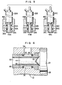
- Fig. 7 shows an example of the intake system which is designed and constructed to permit the transfer of the atomized fuel particles in good order to the intake air flow.
- This intake system is characterized in that the throttle valve 18A disposed at the upstream side of the porous tubular body 32 has a streamline shape.
- the streamline shape of the throttle valve is effective in preventing the undesirable separation of layers of air flowing along the surface of the latter.
- the fuel particles atomized in the porous tubular element are transferred to the intake air flow in a manner to avoid the undesirable coarsening of the fuel particles before they are conveyed into the engine.
- a preferred form'of the intake manifold is as follows:
- an enlarged-diameter portion 52 is connected at its one end to the throttle body 10 and, at its other end, to respective cylinders through branch pipes 54.
- the space in the enlarged-diameter portion 52 is divided into two sections:
- the primary throttle valve 18 when the primary throttle valve 18 operates, the air is introduced solely through the primary chamber 58 of the enlarged-diameter portion 52 so that a comparatively high flow velocity of the intake air is obtained to eliminate the undesirable fluctuation of richness of the mixture and adherence of the fuel particles to the wall of the enlarged-diameter portion. Then, as the secondary throttle valve 20 is put into - effect, the intake air is allowed to flow through both of the primary and the secondary passages 58, 60, so that the supercharging effect provided by the inertia of the intake air flow is never deteriorated.
- the fuel can effectively be atomized by means described hereinunder during low-speed operation with fuel throttle opening.
- the vacuum established at the downstream side of the throttle valve is not so high, so that the air is introduced into the porous tubular element only at a small rate, because of the low vacuum at the downstream side of the throttle valve, resulting in an insufficient atomization of the fuel injected by the fuel injector.
- the intake passage 12 in the throttle body 10 is in communication with an air cleaner 64 which incorporates a reed valve 66.
- the reed valve 66 is communicated with a mixing chamber 70 in the throttle body 10, through an air passage 68.
- the mixing chamber 70 is formed between the primary passage 14 downstream from the primary throttle valve 18 and the porous tubular element 32.
- the reed valve 66 is constituted by a stopper 72, a valve member 74 made of a resilient member and a passage 76.
- the valve member 74 is adapted to normally close the passage 76 due to its resiliency.
- a pulsation of pressure consisting of alternatingly repeated positive and negative pressures is generated in the portion of the intake passage downstream from the air cleaner 64, in accordance with the angles of the crank shaft rotation, as shown in Fig. 10. It is possible to promote the atomization of the fuel through forcibly feeding the air into the mixing chamber 70, by an efficient use of this pulsation of the air pressure.
- valve member 74 is deflected to open the passage 76 to permit the air supply to the mixing chamber 70 only when the "negative" pressure is acting on the reed valve 66.
- the arrangement shown in Fig. 9 may be modified such that the air passage 68 is communicated with the air chamber 42 by a passage shown by broken lines to permit the supply of the air from the reed valve 66 to the air chamber 42.
- a hollow porous tubular element opened at its both ends is disposed such that one of the opened ends thereof is positioned in the vicinity of the fuel discharge orifice of the fuel injector.
- Most part of the fuel injected through the discharge orifice is made to adhere to the inner peripheral surface of the porous tubular element.
- air is fed into the porous tubular element from the space around the latter, through the minute air passages formed across the wall thickness of the-porous tubular element, thereby to form a homogeneous mixture with the fuel adhering to the inner peripheral surface of the porous tubular element. Since the total intake air induced during the suction stroke during idling is homogeneously mixed with the fuel to ensure a steady and smooth idle operation.
- the fuel is effectively atomized into particles of small particle sizes which could never be attained by-the conventional atomizer or the like means to effectively improve the driveability, exhaust gas characteristic and fuel economy of the internal combustion engine.
Applications Claiming Priority (2)
| Application Number | Priority Date | Filing Date | Title |
|---|---|---|---|
| JP135785/78 | 1978-11-06 | ||
| JP53135785A JPS6056908B2 (ja) | 1978-11-06 | 1978-11-06 | 燃料噴射装置のための燃料制御装置 |
Publications (2)
| Publication Number | Publication Date |
|---|---|
| EP0012213A1 true EP0012213A1 (fr) | 1980-06-25 |
| EP0012213B1 EP0012213B1 (fr) | 1982-02-17 |
Family
ID=15159780
Family Applications (1)
| Application Number | Title | Priority Date | Filing Date |
|---|---|---|---|
| EP79104293A Expired EP0012213B1 (fr) | 1978-11-06 | 1979-11-05 | Système d'injection pour un moteur à combustion interne |
Country Status (5)
| Country | Link |
|---|---|
| US (1) | US4325341A (fr) |
| EP (1) | EP0012213B1 (fr) |
| JP (1) | JPS6056908B2 (fr) |
| CA (1) | CA1130153A (fr) |
| DE (1) | DE2962154D1 (fr) |
Cited By (1)
| Publication number | Priority date | Publication date | Assignee | Title |
|---|---|---|---|---|
| GB2278639A (en) * | 1993-06-05 | 1994-12-07 | Ford Motor Co | Emulsifier for an engine fuel injector. |
Families Citing this family (42)
| Publication number | Priority date | Publication date | Assignee | Title |
|---|---|---|---|---|
| JPS5590745U (fr) * | 1978-12-20 | 1980-06-23 | ||
| JPS59119053A (ja) * | 1982-12-25 | 1984-07-10 | Nippon Soken Inc | 燃料霧化用二次空気の供給装置 |
| FR2569241A1 (fr) * | 1984-03-05 | 1986-02-21 | Mesenich Gerhard | Soupape d'injection electromagnetique comportant un dispositif pour atomiser le carburant au moyen d'un courant d'air |
| DE3414201A1 (de) * | 1984-04-14 | 1985-10-17 | Robert Bosch Gmbh, 7000 Stuttgart | Einrichtung zum einspritzen von kraftstoff in brennraeumen |
| JPS611844A (ja) * | 1984-06-15 | 1986-01-07 | Automob Antipollut & Saf Res Center | 燃料噴射装置 |
| ES8707782A1 (es) * | 1985-05-24 | 1987-08-16 | Orbital Eng Pty | Un metodo y un aparato para entregar combustible liquido a un motor de combustion interna. |
| US5082184A (en) * | 1986-05-02 | 1992-01-21 | General Motors Corporation | Fuel injection |
| CA1292651C (fr) * | 1986-05-02 | 1991-12-03 | Ernest R. Stettner | Injection de carburant |
| JP2848491B2 (ja) * | 1988-11-16 | 1999-01-20 | 株式会社日立製作所 | 燃料噴射制御装置 |
| US5054456A (en) * | 1989-11-06 | 1991-10-08 | General Motors Corporation | Fuel injection |
| JPH04252867A (ja) * | 1991-01-25 | 1992-09-08 | Nissan Motor Co Ltd | 内燃機関の燃料供給装置 |
| US5271358A (en) * | 1991-03-20 | 1993-12-21 | Sanshin Kogyo Kabushiki Kaisha | Fuel injection system for engine |
| JPH06241147A (ja) * | 1993-02-12 | 1994-08-30 | Nippondenso Co Ltd | 内燃機関の燃料供給装置 |
| US5401935A (en) * | 1993-05-28 | 1995-03-28 | Heaters Engineering, Inc. | Fuel heating assembly |
| US5529035A (en) * | 1994-11-08 | 1996-06-25 | Hitachi America, Ltd. | Cold start fuel injector with heater |
| DE4446242A1 (de) * | 1994-12-23 | 1996-06-27 | Bosch Gmbh Robert | Kraftstoffeinspritzvorrichtung für einen Verbrennungsmotor |
| DE19522074A1 (de) * | 1995-06-17 | 1996-12-19 | Bosch Gmbh Robert | Kraftstoffzuführvorrichtung für einen Verbrennungsmotor |
| DE19535744A1 (de) * | 1995-09-26 | 1997-03-27 | Bosch Gmbh Robert | Brennstoffeinspritzanordnung für eine Brennkraftmaschine und Verfahren zur Brennstoffeinspritzung |
| US5730367A (en) * | 1996-07-26 | 1998-03-24 | Siemens Automotive Corporation | Fuel injector with air bubble/fuel dispersion prior to injection and methods of operation |
| US5666927A (en) * | 1996-07-26 | 1997-09-16 | Siemens Automotive Corporation | Fuel/air supply system for a fuel injector and methods of operation |
| NL1003980C2 (nl) * | 1996-09-06 | 1998-03-13 | Vialle Beheer B V | Inspuitinrichting. |
| US5836289A (en) * | 1997-06-10 | 1998-11-17 | Southwest Research Institute | Porous element fuel vaporizer |
| US6145496A (en) * | 1998-04-07 | 2000-11-14 | Siemens Automotive Corporation | Fuel injector with porous element for atomizing fuel under air pressure |
| FI107829B (fi) | 1999-06-15 | 2001-10-15 | Markku Juhani Palmu | Laite kaasun imemiseksi ja sekoittamiseksi polttonesteen virtaukseen |
| US6769421B2 (en) * | 1999-08-24 | 2004-08-03 | Randolph M. Pentel | Method and apparatus for vaporizing fuel |
| US7249596B2 (en) * | 2002-03-22 | 2007-07-31 | Philip Morris Usa Inc. | Fuel system for an internal combustion engine and method for controlling same |
| US6913004B2 (en) * | 2002-03-22 | 2005-07-05 | Chrysalis Technologies Incorporated | Fuel system for an internal combustion engine and method for controlling same |
| US6971371B2 (en) * | 2003-09-30 | 2005-12-06 | Honda Motor Co., Ltd. | Air-fuel mixing and delivery apparatus for an internal combustion engine |
| US20050193993A1 (en) * | 2004-03-04 | 2005-09-08 | Dale Thomas D. | Fuel vapor systems for internal combustion engines |
| US7762235B2 (en) * | 2004-03-04 | 2010-07-27 | Continental Automotive Systems Us, Inc. | Acoustic noise reduction of a gaseous fuel injector |
| JP4074942B2 (ja) * | 2004-04-16 | 2008-04-16 | 株式会社ケーヒン | 燃料供給装置 |
| JP4422073B2 (ja) * | 2005-06-07 | 2010-02-24 | 株式会社ケーヒン | 二輪車用の多連スロットルボデー |
| US20090145977A1 (en) * | 2007-12-05 | 2009-06-11 | Jan Ihle | Injection molded nozzle and injector comprising the injection molded nozzle |
| US7973639B2 (en) * | 2007-12-05 | 2011-07-05 | Epcos Ag | PTC-resistor |
| US20090148802A1 (en) * | 2007-12-05 | 2009-06-11 | Jan Ihle | Process for heating a fluid and an injection molded molding |
| US20090146042A1 (en) * | 2007-12-05 | 2009-06-11 | Jan Ihle | Mold comprising a ptc-ceramic |
| US20090148657A1 (en) * | 2007-12-05 | 2009-06-11 | Jan Ihle | Injection Molded PTC-Ceramics |
| US9034210B2 (en) * | 2007-12-05 | 2015-05-19 | Epcos Ag | Feedstock and method for preparing the feedstock |
| US7886725B1 (en) | 2009-10-15 | 2011-02-15 | Advanced Mileage Technologies, LLC | Fuel economizer fuel vapor system for internal combustion engine |
| US8020537B2 (en) * | 2009-10-15 | 2011-09-20 | Advanced Mileage Technologies, LLC | Fuel economizer fuel vapor system for internal combustion engine |
| DE102018200410A1 (de) * | 2018-01-11 | 2019-07-11 | Ford Global Technologies, Llc | Vorrichtung zur Schmierstoffdosierung |
| CN114278478A (zh) * | 2021-12-13 | 2022-04-05 | 上海工程技术大学 | 缓释夹气喷射气体喷嘴 |
Citations (8)
| Publication number | Priority date | Publication date | Assignee | Title |
|---|---|---|---|---|
| BE369935A (fr) * | ||||
| FR574654A (fr) * | 1923-03-07 | 1924-07-17 | Carburateur | |
| FR1535593A (fr) * | 1967-06-26 | 1968-08-09 | Representation D Organisation | Injecteur pneumatique pour moteurs, réacteurs, générateurs de gaz et autres appareils |
| US3404667A (en) * | 1965-06-15 | 1968-10-08 | Sibe | Fuel injection devices for internal combustion engines |
| US3656464A (en) * | 1970-03-30 | 1972-04-18 | Fuel Injection Eng Co | Fuel injection nozzle and system |
| FR2147631A5 (fr) * | 1971-07-23 | 1973-03-09 | Kraus Werner | |
| US3834678A (en) * | 1971-05-25 | 1974-09-10 | R Baribeau | Fuel injection nozzle for internal combustion engine |
| FR2373749A1 (fr) * | 1976-12-10 | 1978-07-07 | Bendix Corp | Pulverisateur de combustible assiste par air |
Family Cites Families (7)
| Publication number | Priority date | Publication date | Assignee | Title |
|---|---|---|---|---|
| US1872931A (en) * | 1928-03-19 | 1932-08-23 | Doherty Res Co | Fuel supply for internal combustion engines |
| US3583635A (en) * | 1969-02-24 | 1971-06-08 | Jerome H Lemelson | Spraying systems |
| US3782639A (en) * | 1972-04-17 | 1974-01-01 | Ford Motor Co | Fuel injection apparatus |
| DE2326680C3 (de) * | 1973-05-25 | 1980-09-25 | Mtu Motoren- Und Turbinen-Union Muenchen Gmbh, 8000 Muenchen | Flammrohr mit Vormischkammer für Brennkammern von Gasturbinentriebwerken |
| JPS5293831A (en) * | 1976-02-04 | 1977-08-06 | Honda Motor Co Ltd | Mixture gas corrector for quick acceleration of internal combustion en gine with sub-combustion chamber |
| US4141327A (en) * | 1976-09-09 | 1979-02-27 | Texas Instruments Incorporated | Early fuel evaporation carburetion system |
| JPS5482528A (en) * | 1977-12-14 | 1979-06-30 | Toyota Motor Corp | Engine air-fuel-mixture supply system |
-
1978
- 1978-11-06 JP JP53135785A patent/JPS6056908B2/ja not_active Expired
-
1979
- 1979-11-05 DE DE7979104293T patent/DE2962154D1/de not_active Expired
- 1979-11-05 US US06/091,459 patent/US4325341A/en not_active Expired - Lifetime
- 1979-11-05 EP EP79104293A patent/EP0012213B1/fr not_active Expired
- 1979-11-06 CA CA339,315A patent/CA1130153A/fr not_active Expired
Patent Citations (8)
| Publication number | Priority date | Publication date | Assignee | Title |
|---|---|---|---|---|
| BE369935A (fr) * | ||||
| FR574654A (fr) * | 1923-03-07 | 1924-07-17 | Carburateur | |
| US3404667A (en) * | 1965-06-15 | 1968-10-08 | Sibe | Fuel injection devices for internal combustion engines |
| FR1535593A (fr) * | 1967-06-26 | 1968-08-09 | Representation D Organisation | Injecteur pneumatique pour moteurs, réacteurs, générateurs de gaz et autres appareils |
| US3656464A (en) * | 1970-03-30 | 1972-04-18 | Fuel Injection Eng Co | Fuel injection nozzle and system |
| US3834678A (en) * | 1971-05-25 | 1974-09-10 | R Baribeau | Fuel injection nozzle for internal combustion engine |
| FR2147631A5 (fr) * | 1971-07-23 | 1973-03-09 | Kraus Werner | |
| FR2373749A1 (fr) * | 1976-12-10 | 1978-07-07 | Bendix Corp | Pulverisateur de combustible assiste par air |
Cited By (1)
| Publication number | Priority date | Publication date | Assignee | Title |
|---|---|---|---|---|
| GB2278639A (en) * | 1993-06-05 | 1994-12-07 | Ford Motor Co | Emulsifier for an engine fuel injector. |
Also Published As
| Publication number | Publication date |
|---|---|
| US4325341A (en) | 1982-04-20 |
| EP0012213B1 (fr) | 1982-02-17 |
| CA1130153A (fr) | 1982-08-24 |
| JPS6056908B2 (ja) | 1985-12-12 |
| DE2962154D1 (en) | 1982-03-25 |
| JPS5564152A (en) | 1980-05-14 |
Similar Documents
| Publication | Publication Date | Title |
|---|---|---|
| EP0012213B1 (fr) | Système d'injection pour un moteur à combustion interne | |
| US3782639A (en) | Fuel injection apparatus | |
| US6095437A (en) | Air-assisted type fuel injector for engines | |
| JPS63500323A (ja) | 燃焼室を有する火花点火式内燃機関に液体燃料を噴射する方法 | |
| US3610213A (en) | Fuel injection system | |
| US4280661A (en) | Intermittent injection type fuel injection valve | |
| US20030070659A1 (en) | Intake pipe type engine | |
| US4470391A (en) | Air-fuel mixture intake construction for internal combustion engines | |
| EP1219812B1 (fr) | Dispositif d'injection de carburant pour un moteur à combustion interne | |
| US4099503A (en) | Means for imparting supersonic flow characteristics in the intake manifold of an internal combustion engine | |
| US5069186A (en) | Fuel injection assembly for internal combustion engine | |
| CA1070579A (fr) | Dispositif d'admission des gaz sur moteur a combustion interne | |
| JPS6042352B2 (ja) | 燃料噴射装置 | |
| GB1242288A (en) | Carburetors for internal combustion engines | |
| KR830000215B1 (ko) | 연료 분사장치를 위한 연료 제어장치 | |
| US4086896A (en) | Throttle structure for imparting supersonic characteristics in the intake manifold of an internal combustion engine | |
| JP2002195136A (ja) | 吸気制御装置およびこれを搭載した内燃機関 | |
| GB2027488A (en) | Fuel atomization system | |
| US4276867A (en) | Fuel atomizing device | |
| US4341191A (en) | Fuel injection type carburetor | |
| JPH0118838Y2 (fr) | ||
| JPH0118839Y2 (fr) | ||
| JP2578474Y2 (ja) | 定負圧式気化器 | |
| JPH02549B2 (fr) | ||
| JPH0693941A (ja) | 内燃機関の燃料供給装置 |
Legal Events
| Date | Code | Title | Description |
|---|---|---|---|
| PUAI | Public reference made under article 153(3) epc to a published international application that has entered the european phase |
Free format text: ORIGINAL CODE: 0009012 |
|
| AK | Designated contracting states |
Designated state(s): DE FR GB |
|
| 17P | Request for examination filed |
Effective date: 19800704 |
|
| GRAA | (expected) grant |
Free format text: ORIGINAL CODE: 0009210 |
|
| AK | Designated contracting states |
Designated state(s): DE FR GB |
|
| REF | Corresponds to: |
Ref document number: 2962154 Country of ref document: DE Date of ref document: 19820325 |
|
| PGFP | Annual fee paid to national office [announced via postgrant information from national office to epo] |
Ref country code: FR Payment date: 19920918 Year of fee payment: 14 |
|
| PGFP | Annual fee paid to national office [announced via postgrant information from national office to epo] |
Ref country code: GB Payment date: 19920923 Year of fee payment: 14 |
|
| PGFP | Annual fee paid to national office [announced via postgrant information from national office to epo] |
Ref country code: DE Payment date: 19921231 Year of fee payment: 14 |
|
| PG25 | Lapsed in a contracting state [announced via postgrant information from national office to epo] |
Ref country code: GB Effective date: 19931105 |
|
| GBPC | Gb: european patent ceased through non-payment of renewal fee |
Effective date: 19931105 |
|
| PG25 | Lapsed in a contracting state [announced via postgrant information from national office to epo] |
Ref country code: FR Effective date: 19940729 |
|
| PG25 | Lapsed in a contracting state [announced via postgrant information from national office to epo] |
Ref country code: DE Effective date: 19940802 |
|
| REG | Reference to a national code |
Ref country code: FR Ref legal event code: ST |
|
| PLBE | No opposition filed within time limit |
Free format text: ORIGINAL CODE: 0009261 |
|
| STAA | Information on the status of an ep patent application or granted ep patent |
Free format text: STATUS: NO OPPOSITION FILED WITHIN TIME LIMIT |