EP0011775B1 - Antriebseinheit für Landfahrzeuge - Google Patents
Antriebseinheit für Landfahrzeuge Download PDFInfo
- Publication number
- EP0011775B1 EP0011775B1 EP79104504A EP79104504A EP0011775B1 EP 0011775 B1 EP0011775 B1 EP 0011775B1 EP 79104504 A EP79104504 A EP 79104504A EP 79104504 A EP79104504 A EP 79104504A EP 0011775 B1 EP0011775 B1 EP 0011775B1
- Authority
- EP
- European Patent Office
- Prior art keywords
- drive
- turbine
- vehicle
- drive unit
- gas
- Prior art date
- Legal status (The legal status is an assumption and is not a legal conclusion. Google has not performed a legal analysis and makes no representation as to the accuracy of the status listed.)
- Expired
Links
- 230000005540 biological transmission Effects 0.000 description 7
- 238000001816 cooling Methods 0.000 description 4
- 238000002485 combustion reaction Methods 0.000 description 3
- 230000004323 axial length Effects 0.000 description 2
- 238000010276 construction Methods 0.000 description 2
- 230000008878 coupling Effects 0.000 description 1
- 238000010168 coupling process Methods 0.000 description 1
- 238000005859 coupling reaction Methods 0.000 description 1
- 230000018109 developmental process Effects 0.000 description 1
- 239000000446 fuel Substances 0.000 description 1
Images


Classifications
-
- B—PERFORMING OPERATIONS; TRANSPORTING
- B60—VEHICLES IN GENERAL
- B60K—ARRANGEMENT OR MOUNTING OF PROPULSION UNITS OR OF TRANSMISSIONS IN VEHICLES; ARRANGEMENT OR MOUNTING OF PLURAL DIVERSE PRIME-MOVERS IN VEHICLES; AUXILIARY DRIVES FOR VEHICLES; INSTRUMENTATION OR DASHBOARDS FOR VEHICLES; ARRANGEMENTS IN CONNECTION WITH COOLING, AIR INTAKE, GAS EXHAUST OR FUEL SUPPLY OF PROPULSION UNITS IN VEHICLES
- B60K3/00—Arrangement or mounting of steam or gaseous-pressure propulsion units
- B60K3/04—Arrangement or mounting of steam or gaseous-pressure propulsion units of turbine type
Definitions
- the invention relates to a drive unit for land vehicles, in particular armored tracked vehicles, with a gas turbine, consisting of a gas generator and a downstream utility turbine, which acts mechanically via a drive connection on the driving and steering gear, the gas turbine being arranged in the direction of the vehicle's longitudinal axis ,
- the air inlet socket are provided close to the top wall and the exhaust outlet socket close to the rear wall of the vehicle and the gas generator has a drive connection to the auxiliary units arranged in the drive and steering gear.
- Such an arrangement may still be sufficiently reliable for vehicles for the civilian sector, but not for vehicles which are used in the military sector.
- the FR-A 1250244 which has also become known, shows that the gear unit in tracked vehicles is much larger, so that a very large, unavailable space is required for the drive unit.
- the FR-A 12 50 244 solves the space problem in tracked vehicles by arranging the gas turbine above the transmission and installing both transversely to the longitudinal axis of the vehicle. In this case, however, only a single drive from the utility turbine of the gas turbine set to the transmission can be provided. The auxiliary units must therefore also be driven from this single connection.
- the object of the present invention is to propose an arrangement of the drive device for a land vehicle that is as small as possible, but nevertheless robust enough to be used in the military field and with which a separate drive of the steering and travel gear on the one hand and the auxiliary units on the other hand is possible.
- This object is achieved in that the transmission is arranged below the gas turbine transversely to the longitudinal axis of the vehicle, and that the drive connection of the gas generator with the interposition of a clutch on the front end of the drive and steering gear, while the drive connection of the power turbine on the rear end of the drive and steering gear is arranged.
- the known advantages of a gas turbine such as high performance with small dimensions, low oil heat of the engine to be cooled and not so great necessary purity of the intake combustion air as in a piston engine, with the requirements in vehicle construction, high power density based on the used space, united. Since the gas turbine has a greater axial length than the width of the driving and steering gear, the two separate drives can each be introduced into the driving and steering gear in the shortest possible way in a space-saving manner. This eliminates the complex construction of two coaxial drive shafts.
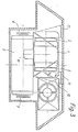
- Fig. 1 the drive unit of a tank is schematically visible. It consists of a gas turbine 1, which has a gas generator and a working turbine, an oil cooling system 9, a driving and steering gear 5 with the drive shafts 6 and 7, and a drive 8 between the working turbine and the driving and steering gear 5.
- the turbine set 1 is arranged above the driving and steering gear 5.
- the compressor of the gas turbine 1 receives its fresh air through the openings 11 arranged on the vehicle surface (FIG. 1).
- the fresh air drawn in first passes into the two air filters 2 (FIG. 2), which can be designed as a cyclone or double cyclone filter, and then into the compressor.
- the sucked-in air is led from the compressor to a heat exchanger, the exhaust gas opening 3 of which is shown in FIG. 2, from there to a combustion chamber 12, through the gas generator turbine to the power turbine and from there through the heat exchanger via its exhaust gas opening through the rear wall 4 into Free.
- a drive connection From the power turbine, which is arranged at the rear end of the drive unit, a drive connection, the housing 8 of which is shown in FIGS. 1 and 3, is created in the drive and steering gear 5 below via a spur gear.
- Another drive connection which is arranged in the housing 10, also leads from the gas generator into the driving and steering gear 5 in order to provide the auxiliary units provided there, e.g. Power supply, steering and auxiliary switching pumps, etc. to drive. In this case it makes sense to arrange a switchable coupling between the power turbine and the gas generator. By splitting into the work turbine and gas generator, the auxiliary units can be operated independently of the driving mode (work turbine).
- FIG. 3 which shows a cross section through a tank with a view of the drive unit space, it is visible how the gas turbine 1 and the oil cooling system 9 are arranged with their longitudinal axes parallel to one another and to the longitudinal axis of the vehicle above the travel and steering gear 5 installed transversely to the longitudinal axis of the vehicle is. 3 that the dimensions of the turbine set are extremely small, so that the entire drive unit of the vehicle takes up much less space than was previously the case with an internal combustion engine as the drive unit of the drive and steering gear.
Landscapes
- Engineering & Computer Science (AREA)
- Chemical & Material Sciences (AREA)
- Combustion & Propulsion (AREA)
- Transportation (AREA)
- Mechanical Engineering (AREA)
- Arrangement Or Mounting Of Propulsion Units For Vehicles (AREA)
- Arrangement Of Transmissions (AREA)
Description
- Die Erfindung bezieht sich auf eine Antriebseinheit für Landfahrzeuge, insbesondere allseits gepanzerte Kettenfahrzeuge, mit einer Gasturbine, bestehend aus einem Gasgenerator und einer nachgeschalteten Nutzturbine, welche mechanisch über eine Antriebsverbindung auf das Fahr-und Lenkgetriebe wirkt, wobei die Gasturbine in Richtung der Fahrzeuglängsachse angeordnet ist, die Lufteinlaßstutzen nahe an der Oberwand und der Abgasauslaßstutzen nahe an der Heckwand des Fahrzeugs vorgesehen sind und der Gasgenerator eine Antriebsverbindung zu den in dem Fahr- und Lenkgetriebe angeordneten Hilfsaggregaten aufweist.
- Insbesondere bei allseits gepanzerten Landfahrzeugen wird gefordert, daß deren Baugröße relativ klein ist bzw. daß bei vorgegebener Baugröße möglichst viele, militärischen Zwecken dienende Einrichtungen untergebracht werden können.
- Hierzu ist es beispielsweise aus der US-A 3446306 bekannt, bei einem Radfahrzeug eine Gasturbine mit koaxial angeordnetem Getriebe in Richtung der Fahrzeuglängsachse anzuordnen. Hierbei sind die Lufteinlaßstutzen nahe an der Oberwand und der Abgasauslaßstutzen nahe an der Heckwand des Fahrzeugs vorgesehen. In das Getriebe führen zwei koaxial angeordnete Antriebswellen, von denen die eine mit dem Gasgenerator und die andere mit der Nutzturbine der Gasturbine gekoppelt sind. Der erste Antrieb dient zum Antreiben der im Getriebe angeordneten Hilfsaggregate, während der zweite der eigentliche Fahrantrieb ist. Aufgrund der koaxialen Anordnung der Gasturbine und des Getriebes ergibt sich eine relativ große axiale Baulänge. Zudem bedingt dieser Anordnung eine komplizierte Lagerung der beiden zum Getriebe führenden und mit unterschiedlichen Drehzahlen umlaufender koaxialen Wellen. Eine derartige Anordnung mag noch bei Fahrzeugen für den zivilen Sektor ausreichend zuverlässig sein, jedoch nicht für Fahrzeuge, die auf dem militärischen Sektor eingesetzt werden. Zudem ist - wie die weiterhin bekannt gewordene FR-A 1250244 zeigt - die Getriebeeinheit bei Kettenfahrzeugen wesentlich größer ausgebildet, so daß ein sehr größer, nicht zur Verfügung stehender Bauraum für die Antriebseinheit benötigt wird.
- Die FR-A 12 50 244 löst das Raumproblem bei Kettenfahrzeugen dadurch, daß sie die Gasturbine oberhalb des Getriebes anordnet und beide quer zur Fahrzeuglängsachse einbaut. Hierbei kann jedoch nur ein einziger Antrieb von der Nutzturbine des Gasturbinensatzes zum Getriebe vorgesehen werden. Die Hilfsaggregate müssen deshalb ebenfalls von dieser einzigen Verbindung aus angetrieben werden.
- Aufgabe der hier vorliegenden Erfindung ist es, eine Anordnung der Antriebseinrichtung für ein Landfahrzeug vorzuschlagen, die möglichst kleinbauend ist, aber trotzdem robust genug, um im militärischen Bereich Anwendung zu finden und mit der ein separater Antrieb des Lenk- und Fahrgetriebes einerseits und der Hilfsaggregate andererseits möglich ist.
- Diese Aufgabe wird erfindungsgemäß dadurch gelöst, daß das Getriebe unterhalb der Gasturbine quer zur Fahrzeuglängsachse angeordnet ist, und daß die Antriebsverbindung des Gasgenerators unter Zwischenschaltung einer Kupplung auf dem vorderseitigen Ende des Fahr- und Lenkgetriebes, während die Antriebsverbindung der Nutzturbine auf dem heckseitigen Ende des Fahr-und Lenkgetriebes angeordnet ist.
- Durch die erfindungsgemäße Ausbildung werden die an sich bekannten Vorteile einer Gasturbine, wie hohe Leistung bei kleinen Abmessungen, geringe abzukühlende Ölwärme des Motors und nicht so große notwendige Reinheit der angesaugten Verbrennungsluft wie bei einem Kolbenmotor, mit den Erfordernissen im Fahrzeugbau, hohe Leistungsdichte bezogen auf den verwendeten Raum, vereinigt. Da die Gasturbine eine größere axiale Länge als die Breite des Fahr-und Lenkgetriebes aufweist, können die beiden separaten Antriebe raumsparend jeweils auf dem kürzesten Wege in das Fahr- und Lenkgetriebe eingeleitet werden. Dadurch entfällt die aufwendige Konstruktion von zwei koaxial zueinander angeordneten Antriebswellen.
- Durch die Weiterbildung gemäß Anspruch 2, nämlich die Gasturbinenlängsachse außermittig zur Fahrzeuglängsachse anzuordnen, wird der Vorteil erreicht, daß neben der Gasturbine genügend Platz vorhanden ist, um die notwendige Ölkühlanlage ebenfalls oberhalb des Getriebes anzuordnen. Damit wird ein äußerst kompakte Antriebseinrichtung geschaffen, die gegenüber herkömmlichen Antriebseinrichtungen einen wesentlich geringeren Raumbedarf aufweist.
- Wird eine Kupplung zwischen der Gasgenerator und der Nutzturbine angeordnet, so ist es möglich die Hilfsaggregate unabhängig von dem Fahrantrieb zu betreiben. Dies senkt die Brennstoffkosten. Eine derartige Möglichkeit ist bei der Anordnung gemäß der FR-A 1250244 unmöglich.
- Im folgenden wird die Erfindung anhand eines ausgewählten Beispiels näher beschrieben.
- Es stellen dar:
- Fig. 1 einen Längsschnitt durch den Motorraum eines Kettenfahrzeugs ;
- Fig. 2 eine Draufsicht auf den Motorraum nach Fig. 1 ;
- Fig. 3 einen Querschnitt durch den Motorraum nach Fig. 1 ;
- In Fig. 1 ist die Antriebseinheit eines Panzers schematisch sichtbar. Sie besteht aus einer Gasturbine 1, die einen Gasgenerator und eine Arbeitsturbine aufweist, eine Ölkühlanlage 9, ein Fahr- und Lenkgetriebe 5 mit den Antreibswellen 6 bzw. 7 sowie einen Antrieb 8 zwischen der Arbeitsturbine und dem Fahr- und Lenkgetriebe 5. Der Turbinensatz 1 ist erfindungsgemäß über dem Fahr- und Lenkgetreibe 5 angeordnet. Der Verdichter der Gasturbine 1 erhält seine Frischluft durch die auf der Fahrzeugoberfläche angeordneten Öffnungen 11 (Fig. 1). Die angesaugte Frischluft gelangt zuerst in die beiden Luftfilter 2 (fig. 2), die als Zyklon bzw. Doppelzyklonfilter ausgebildet sein können, und dann in den Verdichter.
- Anschließend wird die angesaugte Luft von dem Verdichter zu einem Wärmetauscher geführt, dessen Abgasöffnung 3 in Fig. 2 dargestellt ist, von dort zu einer Brennkammer 12, durch die Gasgeneratorturbine zu der Arbeitsturbine und von dort durch den Wärmetauscher über dessen Abgasöffnung durch die Heckwand 4 ins Freie. Von der Arbeitsturbine, welche am heckseitigen Ende der Antriebseinheit angeordnet ist, wird über ein Stirnradgetriebe eine Antriebsverbindung, deren Gehäuse 8 in Fig. 1 und 3 dargestellt ist, in das unten liegende Fahr- und Lenkgetriebe 5 geschaffen.
- Eine weitere Antriebsverbindung, die in dem Gehäuse 10 angeordnet ist, führt von dem Gasgenerator ebenfalls in das Fahr- und Lenkgetriebe 5, um die dort vorgesehenen Hilfsaggregate, wie z.B. Stromversorgung, Lenk- und Schalthilfspumpen etc., anzutreiben. In diesem Fall ist es sinnvoll, zwischen der Arbeitsturbine und dem Gasgenerator eine schaltbare Kupplung anzuordnen. Durch die Aufspaltung in Arbeitsturbine und Gasgenerator können die Hilfsaggregate unabhängig von dem Fahrbetrieb (Arbeitsturbine) betrieben werden.
- Wenn der Turbinensatz 1 außermittig zur Fahrzeuglängsachse angeordnet wird, ist neben ihm Raum genug, um die Ölkühlanlage 9 anzuordnen. Insbesondere in Fig. 3, welche einen Querschnitt durch einen Panzer mit Blick auf den Antriebsaggregateraum darstellt, ist sichtbar, wie die Gasturbine 1 und die Ölkühlanlage 9 mit ihren Längsachsen parallel zueinander und zur Fahrzeuglängsachse über dem quer zur Fahrzeuglängsachse eingebauten Fahr- und Lenkgetriebe 5 angeordnet ist. Weiterhin ist der Fig. 3 zu entnehmen, daß die Abmessungen des Turbinensatzes äußerst gering sind, so daß die gesamte Antriebseinheit des Fahrzeugs wesentlich weniger Platz beansprucht als dies vorher mit einer Brennkraftmachine als Antriebseinheit des Fahr- und Lenkgetriebes der Fall war.
Claims (3)
Applications Claiming Priority (2)
| Application Number | Priority Date | Filing Date | Title |
|---|---|---|---|
| DE2852411 | 1978-12-04 | ||
| DE19782852411 DE2852411A1 (de) | 1978-12-04 | 1978-12-04 | Antriebseinheit fuer landfahrzeuge |
Publications (2)
| Publication Number | Publication Date |
|---|---|
| EP0011775A1 EP0011775A1 (de) | 1980-06-11 |
| EP0011775B1 true EP0011775B1 (de) | 1981-11-11 |
Family
ID=6056277
Family Applications (1)
| Application Number | Title | Priority Date | Filing Date |
|---|---|---|---|
| EP79104504A Expired EP0011775B1 (de) | 1978-12-04 | 1979-11-15 | Antriebseinheit für Landfahrzeuge |
Country Status (3)
| Country | Link |
|---|---|
| US (1) | US4349080A (de) |
| EP (1) | EP0011775B1 (de) |
| DE (1) | DE2852411A1 (de) |
Families Citing this family (3)
| Publication number | Priority date | Publication date | Assignee | Title |
|---|---|---|---|---|
| DE3303578A1 (de) * | 1983-02-03 | 1984-08-09 | Krupp Mak Maschinenbau Gmbh, 2300 Kiel | Kettenfahrzeugausbildung mit einer gasturbineneinheit zur energieerzeugung |
| US4864819A (en) * | 1985-06-03 | 1989-09-12 | General Electric Company | Exhaust system including protective arrangements |
| US7108093B1 (en) | 2003-09-22 | 2006-09-19 | Bae Systems Land & Armaments L.P. | Rear mounted engine design with improved maintenance access for a military vehicle |
Family Cites Families (9)
| Publication number | Priority date | Publication date | Assignee | Title |
|---|---|---|---|---|
| US2854085A (en) * | 1956-02-28 | 1958-09-30 | Continental Aviat & Engineerin | Vehicle engine and transmission |
| US2994394A (en) * | 1956-05-14 | 1961-08-01 | Gen Motors Corp | Gas turbine automobile |
| BE587568A (fr) * | 1959-03-05 | 1960-08-12 | Brevets Aero Mecaniques | Perfectionnements apportés aux véhicules à entraînement par turbine à gaz, notamment aux véhicules à chenilles tels que les chars d'assaut |
| FR1250244A (fr) * | 1960-03-04 | 1961-01-06 | Brevets Aero Mecaniques | Perfectionnements apportés aux véhicules à entrainement par turbine à gaz, notamment aux véhicules à chenilles tels que les chars d'assaut |
| US3191707A (en) * | 1962-06-18 | 1965-06-29 | Adolphe C Peterson | Automotive propulsion system for vehicles |
| FR1347144A (fr) * | 1962-11-13 | 1963-12-27 | Perfectionnements apportés aux véhicules blindés | |
| US3446306A (en) * | 1965-02-01 | 1969-05-27 | Williams Res Corp | Gas turbine for automotive vehicles |
| US3771916A (en) * | 1972-03-20 | 1973-11-13 | Gen Motors Corp | Puffer power plant |
| US3958655A (en) * | 1973-05-22 | 1976-05-25 | United Turbine Ab & Co., Kommanditbolag | Gas turbine engine for vehicle propulsion |
-
1978
- 1978-12-04 DE DE19782852411 patent/DE2852411A1/de not_active Withdrawn
-
1979
- 1979-11-15 EP EP79104504A patent/EP0011775B1/de not_active Expired
- 1979-11-29 US US06/098,389 patent/US4349080A/en not_active Expired - Lifetime
Also Published As
| Publication number | Publication date |
|---|---|
| US4349080A (en) | 1982-09-14 |
| EP0011775A1 (de) | 1980-06-11 |
| DE2852411A1 (de) | 1980-06-12 |
Similar Documents
| Publication | Publication Date | Title |
|---|---|---|
| DE2733902A1 (de) | Schrauben-stroemungsmaschine | |
| DE10254701A1 (de) | Antriebseinheit für Zubehör eines Kraftfahrzeuges mit einem Hybridantrieb | |
| EP2568124B1 (de) | Baueinheit für ein Triebwerk eines Luftfahrzeugs | |
| DE3030850A1 (de) | Wechselgetriebe mit vorgelege | |
| DE3202880A1 (de) | Antriebsanlage zum antrieb und zur lenkung von fahrzeugen durch steuerung der drehzahl der antriebsraeder | |
| DE2849125A1 (de) | Kraftuebertragungssystem fuer einen traktor | |
| EP0325972A2 (de) | Kühleranordnung, insbesondere für einen Fahrzeugantrieb | |
| EP0282784B1 (de) | Gasturbinenanlage für Hubschrauber | |
| DE2925353A1 (de) | Landwirtschaftlich genutzter traktor | |
| DE10316675A1 (de) | Hydrostatisches Getriebe | |
| CH715236A2 (de) | Motorfahrzeugantrieb. | |
| EP0835993A2 (de) | Antriebseinheit mit einem Motor, einem Getriebe und einer Wasserpumpe | |
| EP0445407B1 (de) | Antriebs-Aggregat, insbesondere zum Antrieb eines Fahrzeuges | |
| EP1514010B1 (de) | Modulartig aufgebaute brennkraftmaschine | |
| DE4143102A1 (de) | Kraftuebertragungsteil fuer ein kraftfahrzeug | |
| DE3100107A1 (de) | Turbolader fuer verbrennungskraftmaschinen | |
| DE19939814A1 (de) | Brennkraftmaschine zum Antrieb eines Kraftfahrzeuges | |
| DE102010024896A1 (de) | Modularer Hybridantrieb insbesondere für den Antrieb von Personenkraftwagen | |
| DE3139710A1 (de) | Getriebevorrichtung fuer ein vierradgetriebenes kraftfahrzeug | |
| EP0011775A1 (de) | Antriebseinheit für Landfahrzeuge | |
| DE4029058C2 (de) | ||
| EP0485442B1 (de) | Getriebeeinheit für ein zwei triebachsen aufweisendes kraftfahrzeug | |
| DE19509002C2 (de) | Thermostatanbaupositionsstruktur | |
| DE2451741C2 (de) | Gasturbinentriebwerk für Fahrzeuge | |
| EP1620287B1 (de) | Antriebsaggregat für kraftfahrzeuge |
Legal Events
| Date | Code | Title | Description |
|---|---|---|---|
| PUAI | Public reference made under article 153(3) epc to a published international application that has entered the european phase |
Free format text: ORIGINAL CODE: 0009012 |
|
| AK | Designated contracting states |
Designated state(s): BE FR GB NL |
|
| 17P | Request for examination filed |
Effective date: 19801021 |
|
| GRAA | (expected) grant |
Free format text: ORIGINAL CODE: 0009210 |
|
| AK | Designated contracting states |
Designated state(s): BE FR GB NL |
|
| PGFP | Annual fee paid to national office [announced via postgrant information from national office to epo] |
Ref country code: FR Payment date: 19891008 Year of fee payment: 11 |
|
| PGFP | Annual fee paid to national office [announced via postgrant information from national office to epo] |
Ref country code: BE Payment date: 19891020 Year of fee payment: 11 |
|
| PGFP | Annual fee paid to national office [announced via postgrant information from national office to epo] |
Ref country code: GB Payment date: 19891031 Year of fee payment: 11 |
|
| PGFP | Annual fee paid to national office [announced via postgrant information from national office to epo] |
Ref country code: NL Payment date: 19891130 Year of fee payment: 11 |
|
| PG25 | Lapsed in a contracting state [announced via postgrant information from national office to epo] |
Ref country code: GB Effective date: 19901115 |
|
| PG25 | Lapsed in a contracting state [announced via postgrant information from national office to epo] |
Ref country code: BE Effective date: 19901130 |
|
| BERE | Be: lapsed |
Owner name: KLOCKNER-HUMBOLDT-DEUTZ A.G. Effective date: 19901130 |
|
| PG25 | Lapsed in a contracting state [announced via postgrant information from national office to epo] |
Ref country code: NL Effective date: 19910601 |
|
| GBPC | Gb: european patent ceased through non-payment of renewal fee | ||
| NLV4 | Nl: lapsed or anulled due to non-payment of the annual fee | ||
| PG25 | Lapsed in a contracting state [announced via postgrant information from national office to epo] |
Ref country code: FR Effective date: 19910731 |
|
| REG | Reference to a national code |
Ref country code: FR Ref legal event code: ST |
|
| PLBE | No opposition filed within time limit |
Free format text: ORIGINAL CODE: 0009261 |
|
| STAA | Information on the status of an ep patent application or granted ep patent |
Free format text: STATUS: NO OPPOSITION FILED WITHIN TIME LIMIT |