EP0010684A1 - Schloss - Google Patents
Schloss Download PDFInfo
- Publication number
- EP0010684A1 EP0010684A1 EP79103996A EP79103996A EP0010684A1 EP 0010684 A1 EP0010684 A1 EP 0010684A1 EP 79103996 A EP79103996 A EP 79103996A EP 79103996 A EP79103996 A EP 79103996A EP 0010684 A1 EP0010684 A1 EP 0010684A1
- Authority
- EP
- European Patent Office
- Prior art keywords
- bolt
- lock
- lock case
- operating member
- night
- Prior art date
- Legal status (The legal status is an assumption and is not a legal conclusion. Google has not performed a legal analysis and makes no representation as to the accuracy of the status listed.)
- Granted
Links
- 230000005540 biological transmission Effects 0.000 claims description 33
- 230000000717 retained effect Effects 0.000 claims description 6
- 230000000903 blocking effect Effects 0.000 claims description 4
- 229910000831 Steel Inorganic materials 0.000 claims description 3
- 239000010959 steel Substances 0.000 claims description 3
- 238000004519 manufacturing process Methods 0.000 description 2
- 230000007935 neutral effect Effects 0.000 description 2
- 241000169624 Casearia sylvestris Species 0.000 description 1
- XAGFODPZIPBFFR-UHFFFAOYSA-N aluminium Chemical compound [Al] XAGFODPZIPBFFR-UHFFFAOYSA-N 0.000 description 1
- 229910052782 aluminium Inorganic materials 0.000 description 1
- 239000004411 aluminium Substances 0.000 description 1
- 239000011521 glass Substances 0.000 description 1
- 238000003475 lamination Methods 0.000 description 1
Images


Classifications
-
- E—FIXED CONSTRUCTIONS
- E05—LOCKS; KEYS; WINDOW OR DOOR FITTINGS; SAFES
- E05B—LOCKS; ACCESSORIES THEREFOR; HANDCUFFS
- E05B59/00—Locks with latches separate from the lock-bolts or with a plurality of latches or lock-bolts
Definitions
- This invention relates to a lock which comprises a lock case, a night bolt which is swingably mounted inside the lock case and in an endmost position thereof, namely the closing position, projects with the one end through an opening in the lock case outside said case, and in another endmost position, namely the opening position, is swung inside the lock case, a cylinder lock mechanism which is mounted on the lock case and enters with the rotating operating member thereof said lock case, and a transmission between said operating member and night bolt to swing by rotating of the operating member in the one and respectively in the other direction, the night bolt out of and back in said lock case.
- lock case is meant in this application but a frame on which all of the movable parts of the lock are mounted.
- Said lock case is generally a completely-enclosed box but it can also be provided with large openings in the walls and be comprised structurally of a plurality of parts.
- wall of the lock case through which projects said bolt is a separate elongated plate which extends with both ends thereof outside the remainder of the lock case. The lock case is then fastened on a door by means of said projecting ends.
- Locks with swinging night bolts are already in use as they have some advantages relative to the known locks with a rectilinear-sliding night bolt.
- a better closing is obtain able with a swinging bolt than with a rectilinear-sliding bolt.
- the length of a rectilinear-sliding bolt is always limited by the size of the lock case along the movement direction. Said size is for example relatively small when the lock case has to be built-in into a sectional part from an aluminium door which is comprised of 'a frame wherein glass enters. This results in such a bolt in the closing position, projecting with but a short portion inside the lock case or with but a short portion outside said case. In both cases the closing obtained with said bolt is not very strong.
- the bolt can either spring out of the lock case or spring out of the receiving opening which is provided in the sectional part facing said lock.
- a swinging bolt can be designed for the same lock case width, with a longer length than the sliding bolt in such a way that in the closing position, the swinging bolt lies with a larger portion inside the lock case and also projects with a larger portion outside said lock case, which results in a better locking.
- a swinging bolt can be provided with a hook-like end which allows the use of the lock with sliding doors whereby the bolt has to hook behind a wall in the closing position.
- Locks with swinging night bolt have but a night bolt only, so that also during the day such night bolt has to be used if it is desired to retain the door the lock is mounted on closed.
- the invention has for object to obviate said drawbacks and to provide a lock with swinging night bolt which is lockable without using the night bolt but whereby the complete unlocking of the lock can be obtained through the cylinder lock mechanism and a key.
- the lock comprises both a day bolt which is mounted to be slidable to-and-fro through an opening in the lock case wall, and a transmission between the operating member of the cylinder lock mechanism and the day bolt to move said day bolt by rotating the operating member in a particular direction.
- the lock comprises a holder for a door handle rod, said holder being rotatably mounted inside the lock case about an axis which runs substantially in parallel relationship with the swinging axis of the night bolt, and a transmission between said holder and the day bolt, said transmission may coincide partly with that transmission between the operating member of a cylinder lock mechanism and said day bolt.
- the day bolt can be brought to the open position both with a handle and with a key.
- This key-opening may for instance occur following the bringing to the open position of the night bolt.
- the invention has also for object to provide a lock of the above-defined type whereby the swinging bolt can be operated in a very simple way.
- the rotating operating member of the cylinder lock mechanism comprises a ring provided with a projection, said projection cooperating with the transmission between said operating member and the night bolt.
- the transmission between the operating member of the cylinder slot mechanism and the night bolt comprises an arm which is hingedly made fast with the one end thereof to the night bolt in eccentric relationship with the swinging fastening of said night bolt to the lock case, which arm is provided at the other end thereof with a notch wherein the operating member projection comes to lie when in the open position of the night bolt, the operating member is rotated in the closing direction and when in the closed position of the night bolt, said operating member is rotated in the opening direction to drive along the arm by the further rotating in said direction and thus to swing the night bolt.
- the invention also relates to a lock which comprises a lock case, a night bolt which is movably mounted inside the lock case an in one end position, namely the closed position, projects with one end thereof through an opening in the lock case outside said lock case and in another end position, namely the open position, lies inside the lock case, an operating member to be swung with a key which is swingably mounted in the lock case, and a transmission between said operating member and the night bolt.
- the operating member can be part of a cylinder lock.
- the night bolt can be linearly slidable as well as swingable.
- the invention has now for object to provide a lock with night bolt whereby the sawing-away of that portion projecting outside the lock case in the closed position, of the bolt is substantially impossible.
- the night bolt as least in the portion thereof lying in the closed position directly on the outer side of the lock case, is provided with at least one recess running in that direction along which the bolt projects outside in said closed position, while the lock comprises a round pin which enters loosely said recess.
- the pin is made from steel which has been surface-nitrated.
- the invention also pertains to a lock which comprises a lock case, a bevelled day bolt which is movably mounted inside the lock case and in one end position, namely the closed position, projects with the bevelled end thereof through an opening in the lock case outside said lock case, but in another end position, namely the open position, enters the lock case, a resilient element which pushes the day bolt outwards, and a lever which cooperates with the day bolt to bring same inside the lock case against the action of said resilient element.
- the invention has for object to provide such a lock whereby the day bolt can be swung over 180° in a relatively simple way after mounting, to bring the bevel on the desired side.
- the day bolt comprises a bevelled head, a tie rod connecting thereto and an end projecting outside said rod which is connected by said rod to the head and which cooperates with the lever
- the lock case comprises a guide wherein said end fits slidingly but not swingably during the sliding from the open to the closed position of the day bolt
- the lock comprises a resilient stop which is mounted inside the lock case, said stop being stronger and thus more difficult to distort than the spring element cooperating with said day bolt, resilient stop which is engaged by a lever portion in the day bolt closed position, in such a way that the lever which pushed the projecting bolt end away against the action of the spring element as the bolt is slid open, is retained normally by the resilient stop in the closed position of the bolt and thus prevents in turn the further movement outwards of said bolt while being able to resiliently deflect the stop under a high enough outside force on the bolt, to allow moving the bolt until the head thereof lies completely outside the lock case and the end thereof is released from the guide and the bolt can thus be swung.
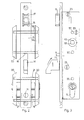
- the lock shown in the figures comprises a lock case 1 which forms a closed box and is comprised of two parallel rectangular side walls 2 and 3, an upstanding rim 4 which stands on two short sides and one long side of side wall 2 and against which bears side wall 3, and a fastening plate 5 which connects to the fourth side of side wall 2 and also connects to rim 4.
- Said fastening plate 5 projects sidewise outside side walls 2 and 3 and also projects with both ends outside the remainder of lock case 1. With said projecting ends said fastening plate 5 is made fast as shown in figure 1 to an upstanding section 6 from a door.
- the fastening plate 5 lies on the outer side of section 6 while the remainder of the lock case is arranged inside an opening of the section and for the major part thereof within the section proper.
- the side wall 3 is comprised of a removable plate which is secured against the rim 4 by means of screws 23 which are screwed into projections 7 and 8 standing on side wall 2.
- the lock further comprises a cylinder lock mechanism 9 which is of a structure known per se and will only be described here as far as necessary to understand the working of the lock.
- the housing 10 of the cylinder lock 9 is secured by means of a screw 11 which passes through the fastening plate 5, to the lock case 1.
- Said housing projects on either side through openings in the side walls 2 and 3.
- said cylinder lock 9 comprises a rotatable operating member which is formed by a ring 12 whereon stands a projection 13.
- Said operating member 12, 13 controls through transmission means two bolts, namely a night bolt 14 and a day bolt 15.
- the night bolt 14 and the day bolt 15 project in closed position respectively through openings 16 and 17 in plate 5.
- bolts 14 and 15 still lie precisely partly inside said openings but mainly on the outer side and in any case in such a way that they do not project outside the lock case 1.
- the screws 21 go through the one key plate 20 wherein the screw heads are sunk, while the screws are screwed with the other end thereof in the other key plate 20 which is provided on that side facing the lock case, with suitably-threaded holes.
- the top screw 21 runs cross-wise through lock case 1, namely through openings 22 in side walls 2 and 3 thereof.
- the bottom screw 21 runs precisely on the outer side of lock case 1.
- That key plate 20 wherein the heads of screws 21 are sunk, is arranged on the door inner side. Consequently the key-plate fastening is not visible from the outer side and the small key plate located on the outer side cannot be removed either.
- Both key plates 20 are moreover provided with bevelled outer edges which converge away from lock case 1.
- the thickness of the small key plates 20 is moreover such that when said key plates are pushed as shown in figure 1 against section 6, the cylinder lock 9 does not or substantially not project outside said key plates 20. Without removing key plates 20, it is thus also impossible to grip with pliers a cylinder lock end that projects outside section 6. Due to the bevelled edges thereof, the small key plates 20 cannot either be gripped with pliers, so that they cannot be forcefully removed either.
- the night bolt 14 is swingably mounted inside lock case 1.
- the axis said bolt swings about is formed by the above-mentioned projection 8 that stands on side wall 2.
- Said bolt 14 is swung from the open position to the closed position or vice versa by the operating member 12, 13 of the cylinder lock mechanism 9 through a transmission.
- Said transmission comprises an arm 24 which is made fast to that side facing side wall 3, of night bolt 14, eccentrically relative to the rotation axis 8 of bolt 14.
- Said fastening is obtained by means of a small shaft 25 which stands on arm 24 and is loosely rotatably fitted inside an opening provided in bolt 14.
- Said small shaft 25 runs as well as rotation axis 8 of bolt 14 and the rotation axis of operating member 12, 13 for the cylinder lock at right angle to side walls 2 and 3.
- the arm 24 extends along the inner side of fastening plate 5 of lock case 1, which plate forms a guide during the alternating sliding of arm 24. That end of arm 24 removed from shaft 25 is provided with an overthickness 24' which projects both towards side wall 2 and away from fastening plate 5. In that portion of said overthickness removed from fastening plate 5 is provided a notch 26 which opens on that overthickness edge which is removed from plate 5.
- said latter end of arm 24 forms sidewise a two-pronged fork. Said latter end with notch 26 lies in the open position of night bolt 14, next to but partly over operating member 12, 13 of cylinder lock mechanism 9. In the figures said operating member has been shown in the neutral position whereby thus the key can be removed from the cylinder lock.
- Said blocking mechanism comprises a slider 28 which is slidable to-and-fro along the cross-wise direction of lock case 1 over side wall 2 and is provided with an upstanding finger 29 running away from side wall 2. During the sliding movement thereof, said slider 28 is guided by two ribs 30 and 31 which stand on side wall 2.
- a leaf spring 32 which is secured by stops 27 and 52, pushes slider 28 constantly in the direction of night bolt 14. That portion of slider 28 on which stands finger 29 extends for the major part along side wall 2, between same and bolt 14, up to a small distance from fastening plate 5. The slider 28 can be pushed away from said plate 5 against the action of leaf spring 32 , by means of a lever 33.
- Said lever is hingedly fastened between the ends thereof by means of a small shaft 34 on side wall 2, directly adjacent fastening plate 5.
- the one leg of lever 33 extends between night bolt 14 and side wall 2 and lies precisely opposite that end of slider 28 facing plate 5.
- the bolt 14 is retained notably by ribs 30 and 31 at a distance from side wall 2 in such a way that as already noted, a portion of slider 28 and thus also a portion of lever 33 can lie movably between bolt 14 and side wall 2.
- the other leg of lever 33 extends between arm 24 and side wall 2 and lies with the one end thereof right next to ring 12 from said operating member 12, 13 of cylinder lock mechanism 9.
- the lever 33 does not exert a force any more on slider 28 whereby thus said slider 28 engages that portion of bolt 14 lying inside lock case 1 and can retain said bolt portion.
- the last-named portion of night bolt 14 is provided with a notch 35 and a protrusion 36.
- the protrusion 36 is so located that when night bolt 14 lies in the open position as shown in figure 5 and slider 28 is pushed with the finger 29 thereof against said bolt 14, the finger 29 lies right next to protrusion 36 in the direction along which bolt 14 is swung from the open position to the closed position.
- Finger 29 prevents as long as slider 28 is not pushed away by lever 33, the swinging of night bolt 14 lying in the open position. Notch 35 in night bolt 14 is so located that when night bolt 14 lies in the closed position as shown in figure 4 and slider 28 is moved farthest away in the direction of said night bolt 14, the finger 29 fits precisely into notch 35. The wall of said notch that lies on the side along which the notch moves during the swinging to open position of bolt 14, then also forms a protrusion which is retained by finger 29. Bolt 14 in closed position is prevented from swinging as long as slider 28 has not been moved by lever 33. In the completely closed position of bolt 14, it is impossible, even if it were possible to reach the end of bolt 14 projecting outside lock case 1, to cause bolt 14 to swing by hitting said end.
- That portion of night bolt 14 which lie in closed position outside lock case 1 can take various shapes. Due to said bolt 14 swinging, the last-mentioned portion thereof can form a hook as shown in figures 1 to 3. It is required for example with sliding doors that bolt 14 by the closing hooks behind a portion of section 19 and stiffening plate 18. In the embodiment as shown in figures 5 and 6, the bolt 14 is not of hook-shape in such a wy that it can only be used on hinged doors.
- At least one cylinder-like hollow 37 is provided in said bolt 14, hollow inside which lies loosely a round pin 38.
- two such hollows 37 are cut-out in said bolt 14.
- Said hollows extend in the lengthwise direction of bolt 14, that is thus in the direction along which the bolt extends in closed position outside lock case 1.
- Both hollows 37 open on that end of bolt 14 which even in closed position still lies inside lock case 1 and run up to some distance from the other end. Said hollows thus lie partly in that portion of bolt 14 extending in closed position outside lock case 1 and certainly right adjacent to fastening plate 5.
- pins 38 Inside each hollow 37 lies a round pin 38 which has substantially the same length as the hollow and thus lie in every case in that hollow portion which lies outside lock case 1 in closed position of bolt 14.
- Pins 38 are made from steel which has been surface-nitrated. When sawing through that portion of bolt 14 projecting outside lock case 1 in closed position, the saw as it reaches the pins 38, will roll over same. The pins 38 will be substantially impossible to saw through.
- the day bolt 15 is comprised of a sidewise-bevelled head 39, an enlarged end 40 and a connecting rod 41 which connects end 40 to head 39.
- a portion 40' fits precisely between a guide formed by two walls 42 standing on side wall 2 of lock case 1 and connecting to the rim thereof.
- a spiral spring 43 which bears on ridge 4 and lies between both walls 42, pushes end 40 in the direction of fastening plate 5 and thus pushes day bolt 15 outwards.
- head 39 lies partly in the opening 17 in plate 5 and partly outside lock case 1.
- Portion 40' from end 40 still lies precisely between both walls 42.
- the head 39 lies completely inside lock case 1 and spring 43 is completely compressed.
- lever 44 When lever 44 is left completely free, it is pushed by spring 43 and end 40 to the position as shown in figure 4 whereby day bolt 15 lies in the closed position. Thereby lever 44 engages with a projection 51 said resilient stop which is formed by one end of said leaf spring 32 which pushes slider 28 against night bolt 14. Said end of leaf spring 32 is stronger and less distortable than spiral spring 43 with the result that under the action of said spring 43 alone the lever cannot swing further in the direction opposite the direction shown by arrow 46. When the action of spring 43 is however helped by an additional pulling force exerted on bolt 15, the projection 51 can then distort leaf spring 32. Lever 44 still swings further until head 39 lies completely outside lock case 1 and portion 40' of end 40 lies between walls 42.
- the night bolt 14 has to be in closed position.
- the bolt can then easily be swung about the lengthwise axis thereof over 180°.
- the leaf spring 32 pushes lever 44 and thus also bolt 15 back to the position as shown in figure 4.
- the swinging of lever 44 can occur in two ways.
- the day bolt 15 can be operated by the cylinder lock mechanism 9.
- the lever 44 is then part of the transmission between day bolt 15 and operating member 12, 13 of said cylinder lock mechanism 9.
- a sliding part 47 is also part of said transmission.
- Said sliding part 47 is a small batten which runs on the side of lever 44, with the one end along the inner side of fastening plate 5, is bent in the location of bolt 14 to run from the side opposite arm 24 about shaft 8 and lies with the end thereof next to arm 24 on the side of cylinder lock mechanism 9.
- said sliding part 47 runs between said bolt 14 and side wall 3 of lock case 1. That end of sliding part 47 which lies on the side of lever 44, lies facing a protrusion 48 from lever 44.
- the projection 13 engages the end of sliding part 47, which end is bent in the direction of lever 33, lies between said lever 33 and side wall 3 and extends somewhat outside arm 24.
- the sliding part 47 further comprises a projection 49 projecting towards fastening plate 5, which is slidable inside a recess 50 which is provided in that side facing side wall 3 of arm 24. It goes without saying that said recess opens on that edge of arm 24 removed from plate 5, above the projecting portion, provided with notch 26, of the overthickness 24' of said arm 24.
- the second way to operate the day bolt 15 occurs through a door handle.
- Said door handle is of a known structure and will not be described in detail here. Said handle has not been shown either in the drawings for clearness sake. Only the holder for the handle rod proper has been shown. Said holder is formed by said shaft 45 the lever 44 swings about, which shaft 45 is provided therefor with a square opening 53. To said shaft 45 connects between lever 44 and side wall 2, an arm 54 which extends in the direction of fastening plate 5 of lock case 1 and the end of which is bent over in the direction of side wall 3. Said bent end lies between that portion connecting to bolt 15, of lever 44 and fastening plate 5.
- a small handle plate 55 is further mounted on either side of section 6 wherein the lock is mounted, about the handle rod proper.
- Both handle plates 55 are fastened to one another and to section 6 in the same way as the key plates 20.
- Said latter handle plate is moreover also mounted on the outer side of the door in such a way that no screws are visible there either.
- the handle plates are identical in shape and size to the key plates 20.
- openings 57 for two screws 56 are provided in side walls 2 and 3 for two screws 56. Said screws 56 can as well as the one screw 21 run through the lock case 1 without being hampered by the parts located inside said case 1 and without hampering the movement of said parts.
- the above-described lock has a high safety against breaking-in and is easy to operate.
- the day bolt can be controlled as well by a handle as by the cylinder lock mechanism which controls the night bolt.
Landscapes
- Lock And Its Accessories (AREA)
- Soil Working Implements (AREA)
- Hydrogenated Pyridines (AREA)
- Pharmaceuticals Containing Other Organic And Inorganic Compounds (AREA)
Priority Applications (1)
| Application Number | Priority Date | Filing Date | Title |
|---|---|---|---|
| AT79103996T ATE4736T1 (de) | 1978-10-20 | 1979-10-16 | Schloss. |
Applications Claiming Priority (2)
| Application Number | Priority Date | Filing Date | Title |
|---|---|---|---|
| BE191242A BE871413A (nl) | 1978-10-20 | 1978-10-20 | Slot |
| BE191242 | 1978-10-20 |
Publications (2)
| Publication Number | Publication Date |
|---|---|
| EP0010684A1 true EP0010684A1 (de) | 1980-05-14 |
| EP0010684B1 EP0010684B1 (de) | 1983-09-21 |
Family
ID=3843154
Family Applications (1)
| Application Number | Title | Priority Date | Filing Date |
|---|---|---|---|
| EP79103996A Expired EP0010684B1 (de) | 1978-10-20 | 1979-10-16 | Schloss |
Country Status (3)
| Country | Link |
|---|---|
| EP (1) | EP0010684B1 (de) |
| AT (1) | ATE4736T1 (de) |
| DE (1) | DE2966197D1 (de) |
Cited By (6)
| Publication number | Priority date | Publication date | Assignee | Title |
|---|---|---|---|---|
| EP0060594A1 (de) * | 1981-03-06 | 1982-09-22 | van Parys, Remi Emiel | Verschluss |
| EP0579003A1 (de) * | 1992-06-25 | 1994-01-19 | Costruzioni Italiane Serrature Affini C.I.S.A. S.p.A. | Einbruchhemmende Vorrichtung für ein Schloss mit drehbarem Riegel |
| GB2306558A (en) * | 1995-10-19 | 1997-05-07 | Parkes Josiah & Sons Ltd | Locks |
| GB2400403A (en) * | 2003-04-09 | 2004-10-13 | Laird Security Hardware Ltd | Lock deadbolt and blocking means for drive arm |
| AT16077U1 (de) * | 2017-02-15 | 2018-12-15 | Roto Frank Ag | Schloss |
| CN112746772A (zh) * | 2021-01-29 | 2021-05-04 | 日荣五金制品(深圳)有限公司 | 防锯断的锁舌 |
Citations (6)
| Publication number | Priority date | Publication date | Assignee | Title |
|---|---|---|---|---|
| DE2152199A1 (de) * | 1971-10-20 | 1973-04-26 | Adams Rite Mfg | Tuerschloss mit einem verriegelungsund klinkenmechanismus |
| GB1338720A (en) * | 1970-08-31 | 1973-11-28 | Adams Rite Mfg | Bolt for a door lock |
| DE7328563U (de) * | 1975-02-06 | Press Und Stanzwerk Brumme F | Schließwerk für ein Einsteckschloß | |
| DE2442467A1 (de) * | 1974-09-05 | 1976-03-25 | Karrenberg Fa Wilhelm | Einsteckschloss |
| DE2527341A1 (de) * | 1975-06-19 | 1976-12-23 | Karrenberg Fa Wilhelm | Schloss, insbesondere einsteckschloss fuer rohrrahmentueren |
| DE2423135B2 (de) * | 1974-05-13 | 1977-08-11 | Westfälisches Metallwerk Franz Schneider, 3492 Brakel | Anbohrsicherungsplatte fuer ein aussenschild einer tuer |
Family Cites Families (1)
| Publication number | Priority date | Publication date | Assignee | Title |
|---|---|---|---|---|
| US3697342A (en) * | 1970-12-16 | 1972-10-10 | Ibm | Method of selective chemical vapor deposition |
-
1979
- 1979-10-16 DE DE7979103996T patent/DE2966197D1/de not_active Expired
- 1979-10-16 AT AT79103996T patent/ATE4736T1/de not_active IP Right Cessation
- 1979-10-16 EP EP79103996A patent/EP0010684B1/de not_active Expired
Patent Citations (6)
| Publication number | Priority date | Publication date | Assignee | Title |
|---|---|---|---|---|
| DE7328563U (de) * | 1975-02-06 | Press Und Stanzwerk Brumme F | Schließwerk für ein Einsteckschloß | |
| GB1338720A (en) * | 1970-08-31 | 1973-11-28 | Adams Rite Mfg | Bolt for a door lock |
| DE2152199A1 (de) * | 1971-10-20 | 1973-04-26 | Adams Rite Mfg | Tuerschloss mit einem verriegelungsund klinkenmechanismus |
| DE2423135B2 (de) * | 1974-05-13 | 1977-08-11 | Westfälisches Metallwerk Franz Schneider, 3492 Brakel | Anbohrsicherungsplatte fuer ein aussenschild einer tuer |
| DE2442467A1 (de) * | 1974-09-05 | 1976-03-25 | Karrenberg Fa Wilhelm | Einsteckschloss |
| DE2527341A1 (de) * | 1975-06-19 | 1976-12-23 | Karrenberg Fa Wilhelm | Schloss, insbesondere einsteckschloss fuer rohrrahmentueren |
Cited By (8)
| Publication number | Priority date | Publication date | Assignee | Title |
|---|---|---|---|---|
| EP0060594A1 (de) * | 1981-03-06 | 1982-09-22 | van Parys, Remi Emiel | Verschluss |
| EP0579003A1 (de) * | 1992-06-25 | 1994-01-19 | Costruzioni Italiane Serrature Affini C.I.S.A. S.p.A. | Einbruchhemmende Vorrichtung für ein Schloss mit drehbarem Riegel |
| GB2306558A (en) * | 1995-10-19 | 1997-05-07 | Parkes Josiah & Sons Ltd | Locks |
| GB2306558B (en) * | 1995-10-19 | 1999-06-30 | Parkes Josiah & Sons Ltd | Locks |
| GB2400403A (en) * | 2003-04-09 | 2004-10-13 | Laird Security Hardware Ltd | Lock deadbolt and blocking means for drive arm |
| GB2400403B (en) * | 2003-04-09 | 2006-08-16 | Laird Security Hardware Ltd | Locks |
| AT16077U1 (de) * | 2017-02-15 | 2018-12-15 | Roto Frank Ag | Schloss |
| CN112746772A (zh) * | 2021-01-29 | 2021-05-04 | 日荣五金制品(深圳)有限公司 | 防锯断的锁舌 |
Also Published As
| Publication number | Publication date |
|---|---|
| ATE4736T1 (de) | 1983-10-15 |
| EP0010684B1 (de) | 1983-09-21 |
| DE2966197D1 (en) | 1983-10-27 |
Similar Documents
| Publication | Publication Date | Title |
|---|---|---|
| EP0661409B1 (de) | Schloss und Schlossvorrichtung für eine Tür oder ein fenster | |
| US4114933A (en) | Lock structure | |
| US4286812A (en) | Security screen door lock | |
| EP1335085A1 (de) | Verschluss für Schiebetür oder -tor | |
| GB2136045A (en) | Espagnolette | |
| GB1133120A (en) | An improved lock | |
| EP0010684A1 (de) | Schloss | |
| US5573287A (en) | Bilateral-type door locking handle assembly | |
| EP0002381B1 (de) | Sperrbarer Handgriff für Fensterflügelverschlüsse | |
| US2628490A (en) | Push-button combination lock | |
| GB2118611A (en) | Apparatus for locking a closure | |
| EP1522661A2 (de) | Türkantenmontiertes Sicherheitsschloss für Schiebetüre | |
| DE3940393A1 (de) | Sicherheitsschloss | |
| US3477260A (en) | Emergency exit lock | |
| GB2056540A (en) | Fastening for sliding doors and windows | |
| KR830003638A (ko) | 자동 크로스 보울트 이중 자물쇠 | |
| JP3844812B2 (ja) | 電気錠装置 | |
| EP0142342A2 (de) | Schloss mit hakenförmigem Riegel | |
| NO753319L (de) | ||
| NO842933L (no) | Anordning ved rigellaas | |
| EP4596817A1 (de) | Automatische mehrpunktverriegelungsanordnung mit sperrschieber und sperrschieber dafür | |
| GB1462351A (en) | Latching device | |
| US2995395A (en) | Lock | |
| US7415854B2 (en) | Safety lock with adjustable-length bolt | |
| JPS5830918Y2 (ja) | 門扉錠 |
Legal Events
| Date | Code | Title | Description |
|---|---|---|---|
| PUAI | Public reference made under article 153(3) epc to a published international application that has entered the european phase |
Free format text: ORIGINAL CODE: 0009012 |
|
| AK | Designated contracting states |
Designated state(s): AT DE FR IT NL |
|
| 17P | Request for examination filed | ||
| ITF | It: translation for a ep patent filed | ||
| GRAA | (expected) grant |
Free format text: ORIGINAL CODE: 0009210 |
|
| AK | Designated contracting states |
Designated state(s): AT DE FR IT NL |
|
| REF | Corresponds to: |
Ref document number: 4736 Country of ref document: AT Date of ref document: 19831015 Kind code of ref document: T |
|
| REF | Corresponds to: |
Ref document number: 2966197 Country of ref document: DE Date of ref document: 19831027 |
|
| ET | Fr: translation filed | ||
| PLBE | No opposition filed within time limit |
Free format text: ORIGINAL CODE: 0009261 |
|
| STAA | Information on the status of an ep patent application or granted ep patent |
Free format text: STATUS: NO OPPOSITION FILED WITHIN TIME LIMIT |
|
| 26N | No opposition filed | ||
| PGFP | Annual fee paid to national office [announced via postgrant information from national office to epo] |
Ref country code: FR Payment date: 19840925 Year of fee payment: 6 |
|
| PGFP | Annual fee paid to national office [announced via postgrant information from national office to epo] |
Ref country code: DE Payment date: 19841129 Year of fee payment: 6 |
|
| PGFP | Annual fee paid to national office [announced via postgrant information from national office to epo] |
Ref country code: AT Payment date: 19861013 Year of fee payment: 8 |
|
| PGFP | Annual fee paid to national office [announced via postgrant information from national office to epo] |
Ref country code: NL Payment date: 19871031 Year of fee payment: 9 |
|
| PG25 | Lapsed in a contracting state [announced via postgrant information from national office to epo] |
Ref country code: AT Effective date: 19891016 |
|
| PG25 | Lapsed in a contracting state [announced via postgrant information from national office to epo] |
Ref country code: NL Effective date: 19900501 |
|
| NLV4 | Nl: lapsed or anulled due to non-payment of the annual fee | ||
| PG25 | Lapsed in a contracting state [announced via postgrant information from national office to epo] |
Ref country code: FR Effective date: 19900629 |
|
| PG25 | Lapsed in a contracting state [announced via postgrant information from national office to epo] |
Ref country code: DE Effective date: 19900703 |
|
| REG | Reference to a national code |
Ref country code: FR Ref legal event code: ST |