EP1522661A2 - Türkantenmontiertes Sicherheitsschloss für Schiebetüre - Google Patents
Türkantenmontiertes Sicherheitsschloss für Schiebetüre Download PDFInfo
- Publication number
- EP1522661A2 EP1522661A2 EP04018552A EP04018552A EP1522661A2 EP 1522661 A2 EP1522661 A2 EP 1522661A2 EP 04018552 A EP04018552 A EP 04018552A EP 04018552 A EP04018552 A EP 04018552A EP 1522661 A2 EP1522661 A2 EP 1522661A2
- Authority
- EP
- European Patent Office
- Prior art keywords
- casing
- frame
- lever
- hook
- rocker
- Prior art date
- Legal status (The legal status is an assumption and is not a legal conclusion. Google has not performed a legal analysis and makes no representation as to the accuracy of the status listed.)
- Withdrawn
Links
- 238000010168 coupling process Methods 0.000 title claims abstract description 10
- 238000005859 coupling reaction Methods 0.000 title claims abstract description 10
- 230000008878 coupling Effects 0.000 title description 5
- 230000009471 action Effects 0.000 claims abstract description 12
- 241000761557 Lamina Species 0.000 claims description 8
- 230000000284 resting effect Effects 0.000 claims description 7
- 238000013459 approach Methods 0.000 claims description 2
- 238000003780 insertion Methods 0.000 description 4
- 230000037431 insertion Effects 0.000 description 4
- 230000000670 limiting effect Effects 0.000 description 2
- 238000012986 modification Methods 0.000 description 1
- 230000004048 modification Effects 0.000 description 1
- 230000035515 penetration Effects 0.000 description 1
- 238000003466 welding Methods 0.000 description 1
Images


Classifications
-
- E—FIXED CONSTRUCTIONS
- E05—LOCKS; KEYS; WINDOW OR DOOR FITTINGS; SAFES
- E05B—LOCKS; ACCESSORIES THEREFOR; HANDCUFFS
- E05B65/00—Locks or fastenings for special use
- E05B65/08—Locks or fastenings for special use for sliding wings
- E05B65/0811—Locks or fastenings for special use for sliding wings the bolts pivoting about an axis perpendicular to the wings
-
- E—FIXED CONSTRUCTIONS
- E05—LOCKS; KEYS; WINDOW OR DOOR FITTINGS; SAFES
- E05B—LOCKS; ACCESSORIES THEREFOR; HANDCUFFS
- E05B63/00—Locks or fastenings with special structural characteristics
- E05B63/0013—Locks with rotary bolt without provision for latching
-
- E—FIXED CONSTRUCTIONS
- E05—LOCKS; KEYS; WINDOW OR DOOR FITTINGS; SAFES
- E05B—LOCKS; ACCESSORIES THEREFOR; HANDCUFFS
- E05B63/00—Locks or fastenings with special structural characteristics
- E05B63/18—Locks or fastenings with special structural characteristics with arrangements independent of the locking mechanism for retaining the bolt or latch in the retracted position
- E05B63/20—Locks or fastenings with special structural characteristics with arrangements independent of the locking mechanism for retaining the bolt or latch in the retracted position released automatically when the wing is closed
- E05B63/202—Locks or fastenings with special structural characteristics with arrangements independent of the locking mechanism for retaining the bolt or latch in the retracted position released automatically when the wing is closed a latch bolt being initially retained in an intermediate position and subsequently projected to its full extent when the wing is closed
Definitions
- the present invention relates to a safety lock with front coupling for sliding doors.
- Sliding doors are widely used for aesthetic or dimensional requirements: the door panel slides (within a rail or by resting on low-friction means), passing from a first configuration, in which it clears completely the opening in the wall, to a second configuration, in which it occupies said opening, resting with its front against the jamb.
- locks which have a front hook that is suitable to engage in an appropriately provided selvage located in a corresponding position on the jamb.
- the lock acts as a bolt.
- the aim of the present invention is to obviate the above-mentioned drawbacks and meet the cited requirements, i.e., by providing a safety lock with front coupling for sliding doors that can act both as a latch and as a bolt and prevents the rotation of the hook when said rotation is not imposed by the rotation of the key in the cylinder.
- an object of the present invention is to provide a safety lock that is simple, relatively easy to provide in practice, safe in use, effective in operation, and has a relatively low cost.
- the present front-coupling safety lock for sliding doors of the type that comprises a hook element that is pivoted inside a casing of said lock and is suitable to rotate about said pivot until it protrudes partially from said casing, engaging within a respective selvage mounted on the jamb, characterized in that said hook is constituted by an angular lever that is pivoted to the casing at one of its ends, with a tab that protrudes laterally to the side of said pivoting point to which the end of a frame is pivoted, said frame being suitable to perform an axial translational motion by way of the action of a key-operated cylinder, said frame being associated with a lever provided with an end tooth that is suitable to engage, by way of the action of an elastic means, in respective seats provided on said frame; a rocker being mounted so that it can rotate about its own central portion proximate to said angular lever on the portion that lies opposite the portion provided with the protruding tab, said rocker having an end
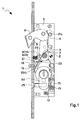
- the reference numeral 1 generally designates a safety lock with front coupling for sliding doors.
- a pivot 3 Inside a casing 2 there is, in a substantially central portion, a pivot 3 on which a hook-like angular lever 4 is mounted so that it can rotate.
- the casing 2 has a front opening 5, through which a triangular head 6 of the lever 4 can protrude from the casing 2.
- the angular lever 4 is constituted by a plurality of superimposed laminas, which are mutually joined by means of transverse elements (screws or pins) or by respective welding spots. Proximate to the pivoting point, the lever 4 has a lateral tab 7 on which the upper end of a frame 8 is pivoted.
- the frame 8 is constituted by two elongated lateral laminas 9, which are identical and mutually parallel, face each other, and are joined by means of transverse metallic flaps 10.
- the two laminas 9 have respective facing holes 11, which are designed to accommodate the pivoting element 12; in a lower region, the frame 8 is mounted on a pin 13 that protrudes from the frame 2 by means of slots 14.
- a lever 15 with an end tooth 16 is also rotatably mounted on the pin 13 and is interposed between the laminas 9.
- the frame 8 substantially has, between two successive flaps 10, seats 10a and 10b that are designed to accommodate the end tooth 16 of the lever 15, which is forced into said seats by way of the action of a spring 17, which is also mounted at the pin 13.
- a hole 18 is provided at the front portion of the casing 2, below the opening 5 for the exit of the hook-shaped lever 4, and a pin 19 is accommodated therein so that it can slide longitudinally.
- An axially-acting spring 20b acts on the opposite end 20a of the rocker 20 and keeps the end 20a spaced from the casing 2 and rested in a recess 23 of the lever 4.
- a spring 22 acts on the hook-shaped lever 4, forcing it to exit from the casing 2, and its arm 22a rests on the casing 2.
- the protrusion of the comer 20a from the recess 22 due to the counterclockwise rotation of the rocker 20 can be produced by the full-length retraction of the pin 19 into the casing 2, with consequent resting against the lower portion of the rocker 20, overcoming the action of the spring 20b.
- a key-operated cylinder 24 is inserted transversely at the lower portion of the casing 2.
- the bit of the cylinder 24, during the rotation imparted by the key, interferes with the lever 15, turning it clockwise about the pivot 13 and thus disengaging the tooth 16 from the seat 10a (or 10b) comprised between the flaps 10.
- the cylinder 24 is kept in position by means of a screw 25 that passes through the front surface of the casing 2.
- the lock 1 is mounted in a sliding door so that the pin 19 and the head 6 of the hook-shaped lever 4 protrude frontally with respect to said door.
- Closure of the door by means of the lock 1 is achieved by placing the door 1 adjacent to the jamb and turning the key in the closure direction, forcing a movement that is the opposite of the one described previously, thus making the head 6 protrude and locking it in this position by engaging the tooth 16 in the lower seat 10a of the frame 8.
- the lock 1 can also be left so that the head 6 protrudes from the casing 2 when the door is open.
- the pin 16 lies outside the casing 2 and therefore the end 20a of the rocker 20 is forced by the spring 20b into the recess 23 of the lever 4.
- the lever 4 is therefore locked in this position by the rocker 20, while the tooth 16 rests against the rear face of one of the metallic flaps 10 (the one comprised between the seat 10a and the seat 10b).
- the arrangement of the door adjacent to the jamb entails a retracting rotation of the lever 4, with consequent partial penetration of the head 6 into the casing 2, until the entire head 6 has fully moved beyond the edge of the selvage, entering it fully.
- the pin 19 rests against the jamb, retracting into the casing 2 and releasing the lever 4, which rotates further outward, entailing an upward translational motion of the frame 8 with consequent engagement of the tooth 16 in the seat 10a in the locking position.
- the lock 1 can act both as a simple latch and as a bolt, directly providing separate functions that are currently provided by means of different locks.
Landscapes
- Engineering & Computer Science (AREA)
- Structural Engineering (AREA)
- Lock And Its Accessories (AREA)
Applications Claiming Priority (2)
| Application Number | Priority Date | Filing Date | Title |
|---|---|---|---|
| ITBO20030584 | 2003-10-10 | ||
| ITBO20030584 ITBO20030584A1 (it) | 2003-10-10 | 2003-10-10 | Sereratura di sicurezza ad aggancio frontale per porte scorrevoli |
Publications (2)
| Publication Number | Publication Date |
|---|---|
| EP1522661A2 true EP1522661A2 (de) | 2005-04-13 |
| EP1522661A3 EP1522661A3 (de) | 2006-12-13 |
Family
ID=34074076
Family Applications (1)
| Application Number | Title | Priority Date | Filing Date |
|---|---|---|---|
| EP04018552A Withdrawn EP1522661A3 (de) | 2003-10-10 | 2004-08-05 | Türkantenmontiertes Sicherheitsschloss für Schiebetüre |
Country Status (4)
| Country | Link |
|---|---|
| EP (1) | EP1522661A3 (de) |
| CN (1) | CN1605705A (de) |
| IT (1) | ITBO20030584A1 (de) |
| ZA (1) | ZA200400041B (de) |
Cited By (5)
| Publication number | Priority date | Publication date | Assignee | Title |
|---|---|---|---|---|
| EP1990487A3 (de) * | 2007-05-11 | 2011-03-09 | Grundmann Beschlagtechnik GmbH | Türschloss |
| GB2445418B (en) * | 2007-01-05 | 2011-12-21 | Adams Rite Europ Ltd | Lock assembly |
| US8485569B2 (en) | 2007-01-05 | 2013-07-16 | Adams Rite Europe Limited | Lock assembly |
| EP2591187A4 (de) * | 2010-07-05 | 2017-05-17 | Stendals EL AB | Verriegelungsvorrichtung mit schlaganordnung und automatischer verriegelung |
| ES2917348A1 (es) * | 2021-01-07 | 2022-07-07 | La Ind Cerrajera Sa | Cerradura automática de seguridad contra eyección indeseada |
Families Citing this family (4)
| Publication number | Priority date | Publication date | Assignee | Title |
|---|---|---|---|---|
| CN102084076B (zh) * | 2008-06-13 | 2013-03-27 | 开开特股份公司 | 一种锁定设备 |
| EP2318627B1 (de) * | 2008-08-05 | 2012-04-18 | CISA S.p.A. | Universalschloss für schwingtüren |
| CN103670109B (zh) * | 2013-12-31 | 2015-09-02 | 南京康尼机电股份有限公司 | 一种城市轨道车辆移门的开关组件 |
| CN110103243B (zh) * | 2019-05-16 | 2022-05-24 | 江南大学 | 一种图书馆存取书机器人的夹手机构 |
Citations (3)
| Publication number | Priority date | Publication date | Assignee | Title |
|---|---|---|---|---|
| GB918429A (en) | 1960-03-05 | 1963-02-13 | Hallam Sleigh & Cheston Ltd | Improvements in latches for sliding doors |
| FR2704591A1 (fr) | 1993-04-30 | 1994-11-04 | Costa Alain | Serrure à crochet. |
| WO1995000958A1 (en) | 1993-06-22 | 1995-01-05 | W. L. Gore & Associates, Inc. | Retractable gloves for handling objects in isolation |
Family Cites Families (5)
| Publication number | Priority date | Publication date | Assignee | Title |
|---|---|---|---|---|
| JPS52103299A (en) * | 1977-02-22 | 1977-08-30 | Schlegel Uk Ltd | Deaddlock or latch |
| FR2620482B1 (fr) * | 1987-09-15 | 1990-01-19 | D S Croisee | Loquet pour panneau coulissant |
| NZ274117A (en) * | 1993-10-06 | 1997-10-24 | Ladislav Stephan Karpisek | Door lock; comprises a moving bolt lock including a casing having an arcuately movable locking bolt, a slidable latch bolt and an elongated deadlock member |
| DE9411842U1 (de) * | 1994-07-22 | 1994-11-17 | Bks Gmbh, 42549 Velbert | Hakenschwenkriegelschloß, insbesondere zur Verwendung als Einsteck-Rohrprofilschloß |
| US5622065A (en) * | 1995-11-06 | 1997-04-22 | Persiano; Anthony M. | Locking mechanism |
-
2003
- 2003-10-10 IT ITBO20030584 patent/ITBO20030584A1/it unknown
-
2004
- 2004-01-05 ZA ZA200400041A patent/ZA200400041B/xx unknown
- 2004-08-05 EP EP04018552A patent/EP1522661A3/de not_active Withdrawn
- 2004-09-06 CN CN 200410077198 patent/CN1605705A/zh active Pending
Patent Citations (3)
| Publication number | Priority date | Publication date | Assignee | Title |
|---|---|---|---|---|
| GB918429A (en) | 1960-03-05 | 1963-02-13 | Hallam Sleigh & Cheston Ltd | Improvements in latches for sliding doors |
| FR2704591A1 (fr) | 1993-04-30 | 1994-11-04 | Costa Alain | Serrure à crochet. |
| WO1995000958A1 (en) | 1993-06-22 | 1995-01-05 | W. L. Gore & Associates, Inc. | Retractable gloves for handling objects in isolation |
Cited By (5)
| Publication number | Priority date | Publication date | Assignee | Title |
|---|---|---|---|---|
| GB2445418B (en) * | 2007-01-05 | 2011-12-21 | Adams Rite Europ Ltd | Lock assembly |
| US8485569B2 (en) | 2007-01-05 | 2013-07-16 | Adams Rite Europe Limited | Lock assembly |
| EP1990487A3 (de) * | 2007-05-11 | 2011-03-09 | Grundmann Beschlagtechnik GmbH | Türschloss |
| EP2591187A4 (de) * | 2010-07-05 | 2017-05-17 | Stendals EL AB | Verriegelungsvorrichtung mit schlaganordnung und automatischer verriegelung |
| ES2917348A1 (es) * | 2021-01-07 | 2022-07-07 | La Ind Cerrajera Sa | Cerradura automática de seguridad contra eyección indeseada |
Also Published As
| Publication number | Publication date |
|---|---|
| ZA200400041B (en) | 2004-08-17 |
| ITBO20030584A1 (it) | 2005-04-11 |
| EP1522661A3 (de) | 2006-12-13 |
| CN1605705A (zh) | 2005-04-13 |
Similar Documents
| Publication | Publication Date | Title |
|---|---|---|
| EP1809841B1 (de) | Verarbeitung von über kommunikationsnetze zu übertragenden nachrichten | |
| US8523247B2 (en) | Cylinder lock with pivotally-mounted bolt | |
| US6609739B1 (en) | Locking devices for gates and the like | |
| US7228719B2 (en) | Sliding door lock | |
| RU2324042C2 (ru) | Блокирующий механизм для двери | |
| EP1335085A1 (de) | Verschluss für Schiebetür oder -tor | |
| US8857864B2 (en) | Tamper proof lock and method | |
| EP1522661A2 (de) | Türkantenmontiertes Sicherheitsschloss für Schiebetüre | |
| CN101889124B (zh) | 滑动门和窗户锁 | |
| US20110285149A1 (en) | Multiple access door lock mechanism with reversible cam actuation | |
| EP3749821B1 (de) | Peripheriebaugruppe für mehrpunkt-schlösser | |
| EP2592210B1 (de) | Verriegelungsanordnung für Fenster oder Türen | |
| GB2575170A (en) | Improvements to mortise locks | |
| CN105658884B (zh) | 一种与第一圆筒锁组件和第二圆筒锁组件或转动插销组合的榫眼锁组件 | |
| AU2020268687B2 (en) | Lock assembly | |
| AU2003252202B2 (en) | A Sliding Door Lock | |
| US3337248A (en) | Mortise lock knob locking means | |
| US3469876A (en) | Unit lock dual dead bolts | |
| GB2413591A (en) | Mortice latch with replaceable follower spring | |
| JP4999892B2 (ja) | 自動販売機等の防盗ロック装置 | |
| CA2490922A1 (en) | Sliding door lock | |
| RU2182634C2 (ru) | Дверной замок с засовом с крюком | |
| JP2011102495A (ja) | 錠前のこじ開け防止装置 | |
| CN111868345B (zh) | 锁组件 | |
| JPH0546608Y2 (de) |
Legal Events
| Date | Code | Title | Description |
|---|---|---|---|
| PUAI | Public reference made under article 153(3) epc to a published international application that has entered the european phase |
Free format text: ORIGINAL CODE: 0009012 |
|
| AK | Designated contracting states |
Kind code of ref document: A2 Designated state(s): AT BE BG CH CY CZ DE DK EE ES FI FR GB GR HU IE IT LI LU MC NL PL PT RO SE SI SK TR |
|
| AX | Request for extension of the european patent |
Extension state: AL HR LT LV MK |
|
| RAP1 | Party data changed (applicant data changed or rights of an application transferred) |
Owner name: CISA S.P.A. |
|
| PUAL | Search report despatched |
Free format text: ORIGINAL CODE: 0009013 |
|
| AK | Designated contracting states |
Kind code of ref document: A3 Designated state(s): AT BE BG CH CY CZ DE DK EE ES FI FR GB GR HU IE IT LI LU MC NL PL PT RO SE SI SK TR |
|
| AX | Request for extension of the european patent |
Extension state: AL HR LT LV MK |
|
| 17P | Request for examination filed |
Effective date: 20070521 |
|
| AKX | Designation fees paid |
Designated state(s): AT BE BG CH CY CZ DE DK EE ES FI FR GB GR HU IE IT LI LU MC NL PL PT RO SE SI SK TR |
|
| 17Q | First examination report despatched |
Effective date: 20080627 |
|
| STAA | Information on the status of an ep patent application or granted ep patent |
Free format text: STATUS: THE APPLICATION IS DEEMED TO BE WITHDRAWN |
|
| 18D | Application deemed to be withdrawn |
Effective date: 20130302 |