EP0010552B1 - Procédé et circuit pour mesurer la qualité de réception d'un signal en ondes ultra-courtes modulé en fréquence - Google Patents
Procédé et circuit pour mesurer la qualité de réception d'un signal en ondes ultra-courtes modulé en fréquence Download PDFInfo
- Publication number
- EP0010552B1 EP0010552B1 EP78101222A EP78101222A EP0010552B1 EP 0010552 B1 EP0010552 B1 EP 0010552B1 EP 78101222 A EP78101222 A EP 78101222A EP 78101222 A EP78101222 A EP 78101222A EP 0010552 B1 EP0010552 B1 EP 0010552B1
- Authority
- EP
- European Patent Office
- Prior art keywords
- signal
- output
- pass filter
- frequency
- low
- Prior art date
- Legal status (The legal status is an assumption and is not a legal conclusion. Google has not performed a legal analysis and makes no representation as to the accuracy of the status listed.)
- Expired
Links
Images
Classifications
-
- H—ELECTRICITY
- H04—ELECTRIC COMMUNICATION TECHNIQUE
- H04B—TRANSMISSION
- H04B1/00—Details of transmission systems, not covered by a single one of groups H04B3/00 - H04B13/00; Details of transmission systems not characterised by the medium used for transmission
- H04B1/06—Receivers
- H04B1/16—Circuits
- H04B1/1646—Circuits adapted for the reception of stereophonic signals
- H04B1/1661—Reduction of noise by manipulation of the baseband composite stereophonic signal or the decoded left and right channels
-
- H—ELECTRICITY
- H03—ELECTRONIC CIRCUITRY
- H03J—TUNING RESONANT CIRCUITS; SELECTING RESONANT CIRCUITS
- H03J3/00—Continuous tuning
- H03J3/02—Details
- H03J3/12—Electrically-operated arrangements for indicating correct tuning
- H03J3/14—Visual indication, e.g. magic eye
-
- H—ELECTRICITY
- H04—ELECTRIC COMMUNICATION TECHNIQUE
- H04B—TRANSMISSION
- H04B1/00—Details of transmission systems, not covered by a single one of groups H04B3/00 - H04B13/00; Details of transmission systems not characterised by the medium used for transmission
- H04B1/06—Receivers
- H04B1/10—Means associated with receiver for limiting or suppressing noise or interference
- H04B1/1027—Means associated with receiver for limiting or suppressing noise or interference assessing signal quality or detecting noise/interference for the received signal
-
- H—ELECTRICITY
- H04—ELECTRIC COMMUNICATION TECHNIQUE
- H04B—TRANSMISSION
- H04B17/00—Monitoring; Testing
- H04B17/30—Monitoring; Testing of propagation channels
- H04B17/309—Measuring or estimating channel quality parameters
-
- H—ELECTRICITY
- H04—ELECTRIC COMMUNICATION TECHNIQUE
- H04B—TRANSMISSION
- H04B1/00—Details of transmission systems, not covered by a single one of groups H04B3/00 - H04B13/00; Details of transmission systems not characterised by the medium used for transmission
- H04B1/06—Receivers
- H04B1/10—Means associated with receiver for limiting or suppressing noise or interference
- H04B1/1027—Means associated with receiver for limiting or suppressing noise or interference assessing signal quality or detecting noise/interference for the received signal
- H04B2001/1054—Means associated with receiver for limiting or suppressing noise or interference assessing signal quality or detecting noise/interference for the received signal by changing bandwidth
Definitions
- the invention relates to a method according to the preamble of claim 1 and to a circuit arrangement according to the preamble of claim 2.
- a method and a circuit arrangement of this type are known from DE-OS 23 34 807.
- the multipath propagation of the ultra-short waves results in amplitude and phase interference modulations which impair the reception quality.
- the detection of the mentioned interference modulations is therefore essential.
- the phase interference modulation cannot be detected on the LF side, since during an FM transmission it cannot be determined which phase changes are to be associated with the useful signal and which phase changes are to be assigned to the interference signal.
- the amplitude interference modulation represents a usable interference effect, since FM transmitters always emit a constant amplitude (so-called "full modulation”), so that amplitude fluctuations can only be caused by interference.
- the resulting amplitude fluctuations of the VHF signal are set in relation to its instantaneous frequency in such a way that the frequency-demodulated LF signal (instantaneous frequency) in the X direction and the with in the Y direction amplitude of the VHF signal obtained by an AM detector and modulated by wave reflections can be displayed.
- the frequency-demodulated LF signal instantaneous frequency
- an AM detector with a compressing (logarithmic) demodulation characteristic curve is used, which allows the mapping of the entire, very large range of possible VHF signal amplitudes on the oscilloscope screen, so that a regulation of the IF amplification can be dispensed with.
- the function A ( ⁇ ) shown only allows a quantitative evaluation of the interference modulation due to the non-linear demodulation characteristic.
- an AM demodulator with a linear characteristic curve is provided in the other two references as an AM detector.
- the IF gain must be regulated manually (BBC research report) or by an AGC (DE-OS-23 34 807) in order to match the very large range of possible VHF signal amplitudes to the inevitably limited dynamic range of the AM Adapt demodulator.
- BCC research report BCC research report
- AGC AGC
- the output signal of the AM demodulator does not correspond to the amplitude of the FM signal, but rather to an amplitude standardized by the control properties, i.e. based on a reference level.
- the amplification In the case of manual control of the IF amplification (BBC research report), the amplification must be selected so that the reference axis of the curve reproduced by the oscilloscope is congruent with the abscissa of the scale cross on the oscilloscope screen.
- the reference axis of the curve is an imaginary line, which corresponds to the curve when there are no reflections.
- the mean or peak value of the amplitude or the spectral component of the VHF carrier can be used as a level parameter.
- amplitude fluctuations resulting from multipath propagation of the VHF signal are such that none of the mentioned parameters of the VHF signal is constant, but rather vary with the modulation of the frequency modulation (frequency swing).
- the use of one of these parameters for the automatic control of the IF gain therefore inevitably leads to ongoing changes in the standardization of the output signal of the AM demodulator depending on the modulation of the frequency modulation (frequency swing).
- the reception interference can also only be assessed qualitatively, but not quantitatively.
- the object of the invention is to improve a method and a circuit arrangement of the type mentioned at the outset so that the reception interference caused by multipath propagation of VHF signals can be measured quickly and effortlessly, i.e. quantitatively assessed.
- the task solution according to the invention is based on the knowledge that the mentioned changes in the standardization depending on the frequency swing when using an automatic IF gain control can be avoided by detecting the instantaneous amplitude value of the VHF signal at the moment of the instantaneous frequency swing "zero" and using it as a control criterion.
- This control criterion is independent of the modulation of the frequency modulation, so that the normalized amplitude A / A o at the output of the AM demodulator can be used for measurement purposes for the first time.
- the extreme values of the derivation of this normalized signal amplitude according to the frequency of the VHF signal represent a direct measure of the degree of reflection-related LF interference in the VHF signal and thus a direct measure of the reception quality.
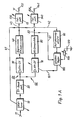
- the left half of an exemplary embodiment of the measuring device according to the invention illustrated in FIG. 1A with the aid of a block diagram largely consists of a known VHF receiver which has been supplemented for the purposes according to the invention.
- 1A has an FM tuner 10, which is fed by an antenna 11 with a frequency-modulated FM signal.
- the FM tuner 10 is followed in the usual way by an IF bandpass filter, which passes the FM signal converted to an intermediate frequency in the tuner 10.
- the output of the band pass 20 fades into two signal branches 50 and 60.
- the signal branch 50 contains an FM intermediate frequency amplifier 30, which is followed by a limiting FM discriminator 40.
- the signal branch 60 contains an AM intermediate frequency amplifier 70, which is followed by an AM demodulator 80.
- the amplifier 70 is controllable, for which a controller 100 is provided, the output of which is connected via a line 101 to the control input of the amplifier 70, the actual value input of which is connected via a line 81 to the output of the demodulator 80 and the setpoint input of which is from a DC voltage source 120 and a series-connected potentiometer 110 existing setpoint adjuster is connected.
- the regulator 100 is keyed by a zero voltage detector 90, for example a window discriminator, the input of which is connected via a line 42 to the output of the discriminator 40. Furthermore, the output signal of the discriminator 40 is fed back via a line 41 to the control input of the FM tuner 10.
- the discriminator 40 and the demodulator 80 lead via lines 43 and 82 to a bandwidth-variable low-pass filter 130 and 140, at the outputs of which the instantaneous frequency swing co or one of the normalized VHF signal amplitudes related to a reference value A o corresponding signal is present, the reference value A o corresponding to the amplitude of the FM signal in the absence of reflections.
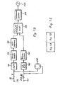
- These signals at the outputs 131 and 141 of the low-pass filters 130 and 140 are fed to the right-hand half of the exemplary embodiment under consideration in FIG. 1B for the measuring device according to the invention.
- FIG. 1C the correct assembly of the block diagrams according to FIGS. 1A and 1B is shown schematically in FIG. 1C.
- the output 131 of the low pass 130 located in the signal branch 50 is connected to a differentiating element 150, which is the derivative of the frequency sweep signal co forms after the time t.
- the output 141 of the low pass 140 is connected to a differentiator 160, which is the derivative of the normalized amplitude signal after time t forms.
- the signal generated at the output of the differentiator 150 for the differential quotient is supplied to the first input of a divider 200 via a magnitude generator 170 consisting, for example, of a bridge rectifier and an operational amplifier and a downstream zero limiter 190, whereas the signal generated at the output of the differentiator 160 for the differential quotient via an amount generator 180 corresponding to the amount generator 170, is fed directly to the second input of the divider 200.
- the divider 200 forms the quotient
- the zero limiter 190 prevents the expression in the denominator of the quotient mentioned to zero and the quotient becomes infinitely large.
- the amount of the output signal from the divider 200 corresponds to the quotient sought that is, the extreme values of the output signal of the divider 200 are a direct measure of the reception quality of the interference-modulated VHF signal arriving at the antenna 11 (FIG. 1A).
- the output signal of the divider 200 is fed to an extreme value memory 210, for example an emitter follower with a capacitor, which determines the extreme values of the divider output signal and supplies it to a digital or analog display device 200, for example a voltage measuring instrument.
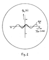
- the above-mentioned differential quotient can also be determined by supplying the signals applied to the outputs 131 and 141 of the low-pass filters 130 and 140 to the X and Y deflection devices of a cathode ray oscillograph 230.
- the cathode ray ozillograph 230 generates on its screen the curve A ( ⁇ ) / A 0 illustrated for a simple case in FIG. 2, the slope of which corresponds to the differential quotient sought.
- the zero voltage detector 90 determines when the output signal of the discriminator 40, which is proportional to the instantaneous frequency swing co, becomes zero.
- the controller 100 is keyed in or activated so that the signal amplitude present at its actual value input at the moment of keying in represents the control criterion.
- This actual value is compared in the usual way with the setpoint set on the potentiometer 110, the resulting error signal being converted by the controller 100 into an actuating signal for the amplifier 70 in accordance with its control characteristic.
- the detector 90 detects a non-zero instantaneous frequency swing 6 o at the output of the discriminator 40, it blanks the controller 100, as a result of which the gain setting of the amplifier 70 present at the time of blanking remains unchanged until the next time the controller 100 is keyed in.
- the constant control of the amplitude at the instantaneous frequency swing "zero" and by suitable selection of the controller setpoint on the potentiometer 110 ensures that the normalization of the amplitude A to the reference variable A o is kept constant during the entire measuring process.
- the reference variable can be made to coincide with the scale abscissa of the scale cross shown there by suitable selection of the controller setpoint on the potentiometer 110 (FIG. 2).
- the measurement accuracy achieved by the constant control of the reference quantity is further increased by the fact that the bandwidth-variable low-pass filters 130 and 140 emit low-noise signals at the inputs of the differentiators 150, 160 and at the X, Y deflection devices of the cathode-ray oscillograph 230 without the to blur the temporal correlation of both signals.
- circuit parts 10, 20, 30 and 40 of the block diagram according to FIG. 1A is known from conventional VHF receivers and requires no further explanation.
Landscapes
- Engineering & Computer Science (AREA)
- Computer Networks & Wireless Communication (AREA)
- Signal Processing (AREA)
- Quality & Reliability (AREA)
- Physics & Mathematics (AREA)
- Electromagnetism (AREA)
- Monitoring And Testing Of Transmission In General (AREA)
- Circuits Of Receivers In General (AREA)
Claims (7)
Priority Applications (2)
| Application Number | Priority Date | Filing Date | Title |
|---|---|---|---|
| EP78101222A EP0010552B1 (fr) | 1978-10-25 | 1978-10-25 | Procédé et circuit pour mesurer la qualité de réception d'un signal en ondes ultra-courtes modulé en fréquence |
| US06/028,810 US4254505A (en) | 1978-10-25 | 1979-04-10 | Normalization method and apparatus used when quantitatively measuring the reception quality of a received frequency-modulated ultrashort-wave signal |
Applications Claiming Priority (1)
| Application Number | Priority Date | Filing Date | Title |
|---|---|---|---|
| EP78101222A EP0010552B1 (fr) | 1978-10-25 | 1978-10-25 | Procédé et circuit pour mesurer la qualité de réception d'un signal en ondes ultra-courtes modulé en fréquence |
Publications (2)
| Publication Number | Publication Date |
|---|---|
| EP0010552A1 EP0010552A1 (fr) | 1980-05-14 |
| EP0010552B1 true EP0010552B1 (fr) | 1983-08-24 |
Family
ID=8185934
Family Applications (1)
| Application Number | Title | Priority Date | Filing Date |
|---|---|---|---|
| EP78101222A Expired EP0010552B1 (fr) | 1978-10-25 | 1978-10-25 | Procédé et circuit pour mesurer la qualité de réception d'un signal en ondes ultra-courtes modulé en fréquence |
Country Status (2)
| Country | Link |
|---|---|
| US (1) | US4254505A (fr) |
| EP (1) | EP0010552B1 (fr) |
Cited By (1)
| Publication number | Priority date | Publication date | Assignee | Title |
|---|---|---|---|---|
| US7495089B2 (en) | 1995-10-23 | 2009-02-24 | The Children's Medical Center Corporation | Therapeutic antiangiogenic endostatin compositions |
Families Citing this family (6)
| Publication number | Priority date | Publication date | Assignee | Title |
|---|---|---|---|---|
| DE3326062A1 (de) * | 1983-07-20 | 1985-01-31 | Gerhard Prof. Dr.-Ing. 8012 Ottobrunn Flachenecker | Detektor zur anzeige von frequenzstoerhubspitzen |
| US4777659A (en) * | 1983-09-26 | 1988-10-11 | U.S. Philips Corporation | Detector for indicating reception disturbances during ultrashort wave broadcast reception |
| DE3334735A1 (de) * | 1983-09-26 | 1985-04-18 | Gerhard Prof. Dr.-Ing. 8012 Ottobrunn Flachenecker | Detektor zum anzeigen von empfangsstoerungen bei mehrwegeempfang |
| US5182882A (en) * | 1991-12-30 | 1993-02-02 | Fedco Automotive Components Co., Inc. | Heater cores having exposed surfaces burnished by wet blasting |
| JP4252454B2 (ja) | 2001-10-05 | 2009-04-08 | タイコ ヘルスケア グループ エルピー | 外科的ステープリングデバイス |
| US8223067B2 (en) * | 2009-11-02 | 2012-07-17 | Invention Planet, LLC | Noise-canceling down-converting detector |
Family Cites Families (9)
| Publication number | Priority date | Publication date | Assignee | Title |
|---|---|---|---|---|
| US2489254A (en) * | 1944-01-04 | 1949-11-29 | Otto F A Arnold | Radio system |
| US2632101A (en) * | 1950-10-23 | 1953-03-17 | Bell Telephone Labor Inc | Reduction of noise in transmission systems |
| NL276220A (fr) * | 1961-03-21 | |||
| US3699463A (en) * | 1970-11-30 | 1972-10-17 | Bell Telephone Labor Inc | Error reduction in communication systems |
| JPS5321241B2 (fr) * | 1972-07-08 | 1978-07-01 | ||
| US3869673A (en) * | 1973-05-21 | 1975-03-04 | Magnavox Co | Method and apparatus for measuring multipath distortion |
| DE2628997C3 (de) * | 1976-06-28 | 1978-11-30 | Siemens Ag, 1000 Berlin Und 8000 Muenchen | System zum Empfang frequenzmodulierter digitaler Nachrichtensignale |
| DE2714439C3 (de) * | 1977-03-31 | 1980-08-14 | Siemens Ag, 1000 Berlin Und 8000 Muenchen | System zum Empfang frequenzmodulierter digitaler Nachrichtensignale |
| US4115774A (en) * | 1977-08-17 | 1978-09-19 | The Bendix Corporation | CW radar AM-noise video-cancellation system |
-
1978
- 1978-10-25 EP EP78101222A patent/EP0010552B1/fr not_active Expired
-
1979
- 1979-04-10 US US06/028,810 patent/US4254505A/en not_active Expired - Lifetime
Cited By (2)
| Publication number | Priority date | Publication date | Assignee | Title |
|---|---|---|---|---|
| US7495089B2 (en) | 1995-10-23 | 2009-02-24 | The Children's Medical Center Corporation | Therapeutic antiangiogenic endostatin compositions |
| US7867975B2 (en) | 1995-10-23 | 2011-01-11 | The Children's Medical Center Corporation | Therapeutic antiangiogenic endostatin compositions |
Also Published As
| Publication number | Publication date |
|---|---|
| EP0010552A1 (fr) | 1980-05-14 |
| US4254505A (en) | 1981-03-03 |
Similar Documents
| Publication | Publication Date | Title |
|---|---|---|
| DE69131074T2 (de) | Automatischer verstärkungsregelschaltkreis mit hoher dynamik | |
| DE19623304C2 (de) | Schaltung und Verfahren zum Messen einer Hochfrequenzleistung | |
| DE69028491T2 (de) | Schaltung zur Anzeige des Signal-Rausch-Verhältnisses für FM-Empfänger | |
| DE3850950T2 (de) | Gerät zur Anzeige der Bildqualität für Satelliten-Rundfunkempfänger. | |
| DE3717841A1 (de) | Funkpeileinrichtung | |
| DE69632341T2 (de) | Spektralanalyseempfänger | |
| EP0010552B1 (fr) | Procédé et circuit pour mesurer la qualité de réception d'un signal en ondes ultra-courtes modulé en fréquence | |
| DE4332161A1 (de) | Hochfrequenzempfänger | |
| DE69522050T2 (de) | AM-Funkempfänger | |
| DE4241362C2 (de) | Rundfunkempfänger | |
| DE60111696T2 (de) | Messung der stärke eines antennensignals mit einem empfänger mit automatischer verstärkungsregelung | |
| DE2334807A1 (de) | Verfahren und geraet zur ermittlung des mehrfachempfangs von frequenz-modulierten rundfunk-stereowellen ("geisterempfang" bei ukw-stereo-rundfunk) | |
| DE2555602B2 (de) | Schaltungsanordnung zur frequenzselektiven Auswertung der Amplituden eines oder mehrerer Signale | |
| DE2724376C3 (de) | Verfahren und Einrichtung zum Messen der Empfangsqualität eines frequenzmodulierten UKW-Signals | |
| DE2724375C3 (de) | Verfahren und Einrichtung zum Messen der Empfangsqualität eines frequenzmodulierten UKW-Signals | |
| DE69227057T2 (de) | Signalstärkeanzeige eines Empfängers | |
| DE3210144C2 (de) | Störfeldstärkenmeßgerät | |
| DE2327190B2 (de) | Klirrfaktormesser | |
| EP0411485B1 (fr) | Procédé pour détecter des distortions multivoies lors de la réception radio à modulation de fréquence, et montage pour réaliser ce procédé | |
| EP0010109A1 (fr) | Méthode et dispositif pour l'appréciation de la qualité de réception d'un signal en ondes ultra-courtes modulé en fréquence | |
| DE3114244C2 (de) | Schaltungs-Anordnung zur Messung der Intermodulationsverzerrung | |
| DE68906976T2 (de) | Messverfahren eines schwellenwertes in einem rauschsignal und automatische messanordnung dafuer. | |
| EP0896429B1 (fr) | Méthode de mesure et de correction de la fréquence d' un oscillateur local | |
| EP1643633A1 (fr) | Circuit utilisant suppression de signaux faux , et procédé | |
| DE2249928A1 (de) | Abstimmhilfe fuer einen selektiven pegelmesser mit einem traegen anzeigeinstrument |
Legal Events
| Date | Code | Title | Description |
|---|---|---|---|
| PUAI | Public reference made under article 153(3) epc to a published international application that has entered the european phase |
Free format text: ORIGINAL CODE: 0009012 |
|
| AK | Designated contracting states |
Designated state(s): BE CH FR GB NL SE |
|
| 17P | Request for examination filed | ||
| GRAA | (expected) grant |
Free format text: ORIGINAL CODE: 0009210 |
|
| AK | Designated contracting states |
Designated state(s): BE CH FR GB NL SE |
|
| PG25 | Lapsed in a contracting state [announced via postgrant information from national office to epo] |
Ref country code: BE Effective date: 19830930 |
|
| PGFP | Annual fee paid to national office [announced via postgrant information from national office to epo] |
Ref country code: FR Payment date: 19831005 Year of fee payment: 6 |
|
| PGFP | Annual fee paid to national office [announced via postgrant information from national office to epo] |
Ref country code: NL Payment date: 19831027 Year of fee payment: 6 |
|
| PG25 | Lapsed in a contracting state [announced via postgrant information from national office to epo] |
Ref country code: CH Effective date: 19831031 |
|
| PGFP | Annual fee paid to national office [announced via postgrant information from national office to epo] |
Ref country code: SE Payment date: 19831031 Year of fee payment: 6 |
|
| PGFP | Annual fee paid to national office [announced via postgrant information from national office to epo] |
Ref country code: BE Payment date: 19831130 Year of fee payment: 6 |
|
| ET | Fr: translation filed | ||
| REG | Reference to a national code |
Ref country code: CH Ref legal event code: PL |
|
| PLBE | No opposition filed within time limit |
Free format text: ORIGINAL CODE: 0009261 |
|
| STAA | Information on the status of an ep patent application or granted ep patent |
Free format text: STATUS: NO OPPOSITION FILED WITHIN TIME LIMIT |
|
| 26N | No opposition filed | ||
| PG25 | Lapsed in a contracting state [announced via postgrant information from national office to epo] |
Ref country code: SE Effective date: 19841026 |
|
| BERE | Be: lapsed |
Owner name: BOSSERT THEODOR TOBIAS Effective date: 19841025 |
|
| PG25 | Lapsed in a contracting state [announced via postgrant information from national office to epo] |
Ref country code: NL Effective date: 19850501 |
|
| NLV4 | Nl: lapsed or anulled due to non-payment of the annual fee | ||
| PG25 | Lapsed in a contracting state [announced via postgrant information from national office to epo] |
Ref country code: FR Free format text: LAPSE BECAUSE OF NON-PAYMENT OF DUE FEES Effective date: 19850628 |
|
| REG | Reference to a national code |
Ref country code: FR Ref legal event code: ST |
|
| PG25 | Lapsed in a contracting state [announced via postgrant information from national office to epo] |
Ref country code: GB Effective date: 19881118 |
|
| EUG | Se: european patent has lapsed |
Ref document number: 78101222.4 Effective date: 19851007 |