EP0010552B1 - Method and circuit for measuring the reception quality of a frequency modulated very high frequency signal - Google Patents
Method and circuit for measuring the reception quality of a frequency modulated very high frequency signal Download PDFInfo
- Publication number
- EP0010552B1 EP0010552B1 EP78101222A EP78101222A EP0010552B1 EP 0010552 B1 EP0010552 B1 EP 0010552B1 EP 78101222 A EP78101222 A EP 78101222A EP 78101222 A EP78101222 A EP 78101222A EP 0010552 B1 EP0010552 B1 EP 0010552B1
- Authority
- EP
- European Patent Office
- Prior art keywords
- signal
- output
- pass filter
- frequency
- low
- Prior art date
- Legal status (The legal status is an assumption and is not a legal conclusion. Google has not performed a legal analysis and makes no representation as to the accuracy of the status listed.)
- Expired
Links
Images
Classifications
-
- H—ELECTRICITY
- H04—ELECTRIC COMMUNICATION TECHNIQUE
- H04B—TRANSMISSION
- H04B1/00—Details of transmission systems, not covered by a single one of groups H04B3/00 - H04B13/00; Details of transmission systems not characterised by the medium used for transmission
- H04B1/06—Receivers
- H04B1/16—Circuits
- H04B1/1646—Circuits adapted for the reception of stereophonic signals
- H04B1/1661—Reduction of noise by manipulation of the baseband composite stereophonic signal or the decoded left and right channels
-
- H—ELECTRICITY
- H03—ELECTRONIC CIRCUITRY
- H03J—TUNING RESONANT CIRCUITS; SELECTING RESONANT CIRCUITS
- H03J3/00—Continuous tuning
- H03J3/02—Details
- H03J3/12—Electrically-operated arrangements for indicating correct tuning
- H03J3/14—Visual indication, e.g. magic eye
-
- H—ELECTRICITY
- H04—ELECTRIC COMMUNICATION TECHNIQUE
- H04B—TRANSMISSION
- H04B1/00—Details of transmission systems, not covered by a single one of groups H04B3/00 - H04B13/00; Details of transmission systems not characterised by the medium used for transmission
- H04B1/06—Receivers
- H04B1/10—Means associated with receiver for limiting or suppressing noise or interference
- H04B1/1027—Means associated with receiver for limiting or suppressing noise or interference assessing signal quality or detecting noise/interference for the received signal
-
- H—ELECTRICITY
- H04—ELECTRIC COMMUNICATION TECHNIQUE
- H04B—TRANSMISSION
- H04B17/00—Monitoring; Testing
- H04B17/30—Monitoring; Testing of propagation channels
- H04B17/309—Measuring or estimating channel quality parameters
-
- H—ELECTRICITY
- H04—ELECTRIC COMMUNICATION TECHNIQUE
- H04B—TRANSMISSION
- H04B1/00—Details of transmission systems, not covered by a single one of groups H04B3/00 - H04B13/00; Details of transmission systems not characterised by the medium used for transmission
- H04B1/06—Receivers
- H04B1/10—Means associated with receiver for limiting or suppressing noise or interference
- H04B1/1027—Means associated with receiver for limiting or suppressing noise or interference assessing signal quality or detecting noise/interference for the received signal
- H04B2001/1054—Means associated with receiver for limiting or suppressing noise or interference assessing signal quality or detecting noise/interference for the received signal by changing bandwidth
Definitions
- the invention relates to a method according to the preamble of claim 1 and to a circuit arrangement according to the preamble of claim 2.
- a method and a circuit arrangement of this type are known from DE-OS 23 34 807.
- the multipath propagation of the ultra-short waves results in amplitude and phase interference modulations which impair the reception quality.
- the detection of the mentioned interference modulations is therefore essential.
- the phase interference modulation cannot be detected on the LF side, since during an FM transmission it cannot be determined which phase changes are to be associated with the useful signal and which phase changes are to be assigned to the interference signal.
- the amplitude interference modulation represents a usable interference effect, since FM transmitters always emit a constant amplitude (so-called "full modulation”), so that amplitude fluctuations can only be caused by interference.
- the resulting amplitude fluctuations of the VHF signal are set in relation to its instantaneous frequency in such a way that the frequency-demodulated LF signal (instantaneous frequency) in the X direction and the with in the Y direction amplitude of the VHF signal obtained by an AM detector and modulated by wave reflections can be displayed.
- the frequency-demodulated LF signal instantaneous frequency
- an AM detector with a compressing (logarithmic) demodulation characteristic curve is used, which allows the mapping of the entire, very large range of possible VHF signal amplitudes on the oscilloscope screen, so that a regulation of the IF amplification can be dispensed with.
- the function A ( ⁇ ) shown only allows a quantitative evaluation of the interference modulation due to the non-linear demodulation characteristic.
- an AM demodulator with a linear characteristic curve is provided in the other two references as an AM detector.
- the IF gain must be regulated manually (BBC research report) or by an AGC (DE-OS-23 34 807) in order to match the very large range of possible VHF signal amplitudes to the inevitably limited dynamic range of the AM Adapt demodulator.
- BCC research report BCC research report
- AGC AGC
- the output signal of the AM demodulator does not correspond to the amplitude of the FM signal, but rather to an amplitude standardized by the control properties, i.e. based on a reference level.
- the amplification In the case of manual control of the IF amplification (BBC research report), the amplification must be selected so that the reference axis of the curve reproduced by the oscilloscope is congruent with the abscissa of the scale cross on the oscilloscope screen.
- the reference axis of the curve is an imaginary line, which corresponds to the curve when there are no reflections.
- the mean or peak value of the amplitude or the spectral component of the VHF carrier can be used as a level parameter.
- amplitude fluctuations resulting from multipath propagation of the VHF signal are such that none of the mentioned parameters of the VHF signal is constant, but rather vary with the modulation of the frequency modulation (frequency swing).
- the use of one of these parameters for the automatic control of the IF gain therefore inevitably leads to ongoing changes in the standardization of the output signal of the AM demodulator depending on the modulation of the frequency modulation (frequency swing).
- the reception interference can also only be assessed qualitatively, but not quantitatively.
- the object of the invention is to improve a method and a circuit arrangement of the type mentioned at the outset so that the reception interference caused by multipath propagation of VHF signals can be measured quickly and effortlessly, i.e. quantitatively assessed.
- the task solution according to the invention is based on the knowledge that the mentioned changes in the standardization depending on the frequency swing when using an automatic IF gain control can be avoided by detecting the instantaneous amplitude value of the VHF signal at the moment of the instantaneous frequency swing "zero" and using it as a control criterion.
- This control criterion is independent of the modulation of the frequency modulation, so that the normalized amplitude A / A o at the output of the AM demodulator can be used for measurement purposes for the first time.
- the extreme values of the derivation of this normalized signal amplitude according to the frequency of the VHF signal represent a direct measure of the degree of reflection-related LF interference in the VHF signal and thus a direct measure of the reception quality.
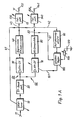
- the left half of an exemplary embodiment of the measuring device according to the invention illustrated in FIG. 1A with the aid of a block diagram largely consists of a known VHF receiver which has been supplemented for the purposes according to the invention.
- 1A has an FM tuner 10, which is fed by an antenna 11 with a frequency-modulated FM signal.
- the FM tuner 10 is followed in the usual way by an IF bandpass filter, which passes the FM signal converted to an intermediate frequency in the tuner 10.
- the output of the band pass 20 fades into two signal branches 50 and 60.
- the signal branch 50 contains an FM intermediate frequency amplifier 30, which is followed by a limiting FM discriminator 40.
- the signal branch 60 contains an AM intermediate frequency amplifier 70, which is followed by an AM demodulator 80.
- the amplifier 70 is controllable, for which a controller 100 is provided, the output of which is connected via a line 101 to the control input of the amplifier 70, the actual value input of which is connected via a line 81 to the output of the demodulator 80 and the setpoint input of which is from a DC voltage source 120 and a series-connected potentiometer 110 existing setpoint adjuster is connected.
- the regulator 100 is keyed by a zero voltage detector 90, for example a window discriminator, the input of which is connected via a line 42 to the output of the discriminator 40. Furthermore, the output signal of the discriminator 40 is fed back via a line 41 to the control input of the FM tuner 10.
- the discriminator 40 and the demodulator 80 lead via lines 43 and 82 to a bandwidth-variable low-pass filter 130 and 140, at the outputs of which the instantaneous frequency swing co or one of the normalized VHF signal amplitudes related to a reference value A o corresponding signal is present, the reference value A o corresponding to the amplitude of the FM signal in the absence of reflections.
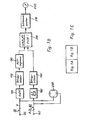
- These signals at the outputs 131 and 141 of the low-pass filters 130 and 140 are fed to the right-hand half of the exemplary embodiment under consideration in FIG. 1B for the measuring device according to the invention.
- FIG. 1C the correct assembly of the block diagrams according to FIGS. 1A and 1B is shown schematically in FIG. 1C.
- the output 131 of the low pass 130 located in the signal branch 50 is connected to a differentiating element 150, which is the derivative of the frequency sweep signal co forms after the time t.
- the output 141 of the low pass 140 is connected to a differentiator 160, which is the derivative of the normalized amplitude signal after time t forms.
- the signal generated at the output of the differentiator 150 for the differential quotient is supplied to the first input of a divider 200 via a magnitude generator 170 consisting, for example, of a bridge rectifier and an operational amplifier and a downstream zero limiter 190, whereas the signal generated at the output of the differentiator 160 for the differential quotient via an amount generator 180 corresponding to the amount generator 170, is fed directly to the second input of the divider 200.
- the divider 200 forms the quotient
- the zero limiter 190 prevents the expression in the denominator of the quotient mentioned to zero and the quotient becomes infinitely large.
- the amount of the output signal from the divider 200 corresponds to the quotient sought that is, the extreme values of the output signal of the divider 200 are a direct measure of the reception quality of the interference-modulated VHF signal arriving at the antenna 11 (FIG. 1A).
- the output signal of the divider 200 is fed to an extreme value memory 210, for example an emitter follower with a capacitor, which determines the extreme values of the divider output signal and supplies it to a digital or analog display device 200, for example a voltage measuring instrument.
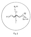
- the above-mentioned differential quotient can also be determined by supplying the signals applied to the outputs 131 and 141 of the low-pass filters 130 and 140 to the X and Y deflection devices of a cathode ray oscillograph 230.
- the cathode ray ozillograph 230 generates on its screen the curve A ( ⁇ ) / A 0 illustrated for a simple case in FIG. 2, the slope of which corresponds to the differential quotient sought.
- the zero voltage detector 90 determines when the output signal of the discriminator 40, which is proportional to the instantaneous frequency swing co, becomes zero.
- the controller 100 is keyed in or activated so that the signal amplitude present at its actual value input at the moment of keying in represents the control criterion.
- This actual value is compared in the usual way with the setpoint set on the potentiometer 110, the resulting error signal being converted by the controller 100 into an actuating signal for the amplifier 70 in accordance with its control characteristic.
- the detector 90 detects a non-zero instantaneous frequency swing 6 o at the output of the discriminator 40, it blanks the controller 100, as a result of which the gain setting of the amplifier 70 present at the time of blanking remains unchanged until the next time the controller 100 is keyed in.
- the constant control of the amplitude at the instantaneous frequency swing "zero" and by suitable selection of the controller setpoint on the potentiometer 110 ensures that the normalization of the amplitude A to the reference variable A o is kept constant during the entire measuring process.
- the reference variable can be made to coincide with the scale abscissa of the scale cross shown there by suitable selection of the controller setpoint on the potentiometer 110 (FIG. 2).
- the measurement accuracy achieved by the constant control of the reference quantity is further increased by the fact that the bandwidth-variable low-pass filters 130 and 140 emit low-noise signals at the inputs of the differentiators 150, 160 and at the X, Y deflection devices of the cathode-ray oscillograph 230 without the to blur the temporal correlation of both signals.
- circuit parts 10, 20, 30 and 40 of the block diagram according to FIG. 1A is known from conventional VHF receivers and requires no further explanation.
Landscapes
- Engineering & Computer Science (AREA)
- Computer Networks & Wireless Communication (AREA)
- Signal Processing (AREA)
- Quality & Reliability (AREA)
- Physics & Mathematics (AREA)
- Electromagnetism (AREA)
- Monitoring And Testing Of Transmission In General (AREA)
- Circuits Of Receivers In General (AREA)
Description
Die Erfindung bezieht sich auf ein Verfahren gemäß dem Oberbegriff des Anspruchs 1 sowie auf eine Schaltungsanordnung gemäß dem Oberbegriff des Anspruchs 2. Ein Verfahren und eine Schaltungsanordnung dieser Art sind aus der DE-OS 23 34 807 bekannt.The invention relates to a method according to the preamble of claim 1 and to a circuit arrangement according to the preamble of claim 2. A method and a circuit arrangement of this type are known from DE-OS 23 34 807.
Bei dem Empfang von frequenzmodulierten Ultrakurzwellen (UKW-FM-Empfang) treten infolge der Mehrwegeausbreitung der Ultrakurzwellen Amplituden- und Phasenstörmodulationen auf, welche die Empfangsqualität beeinträchtigen. Für die Beurteilung der Empfangsqualität ist daher die Erfassung der genannten Störmodulationen unerläßlich. Hierbei kann NFseitig die Phasenstörmudulation nicht erfaßt werden, da während einer UKW-Sendung nicht feststellbar ist, welche Phasenänderungen zum Nutzsignal und welche Phasenänderungen dem Störsignal zuzuordnen sind. Demgegenüber stellt die Amplitudenstörmodulation einen verwertbaren Störeffekt dar, da UKW-Sender stets mit gleichbleibender Amplitude abstrahlen (sogenannte "Vollaussteuerung"), so daß Amplidenschwankungen nur durch Störungen verursacht werden können. Bei bekannten Verfahren zum Erfassen der Amplituden-Störmodulation (DE―OS―23 34 807, "Funkschau", Bd. 43 (1971), Heft 17, Seiten 549 bis 550 und Forschungsbericht der British Broadcasting Corporation BBC RD 1975/33 mit dem Titel "A field strength measuring receiver for band II") werden die entstehenden Amplitudenschwankungen des UKW-Signals dahingehend mit dessen Momentanfrequenz in Relation gesetzt, daß aud einem Oszilloskop in X-Richtung das frequenzdemodulierte NF-Signal (Momentanfrequenz) und in Y-Richtung die mit einem AM-Detektor gewonnene, durch Wellenreflexionen modulierte Amplitude des UKW-Signals dargestellt werden. Für die konstruktive Ausbildung des AM-Detektors sind in diesem Stand der Technik verschiedene Möglichkeiten vorgesehen. Bei dem Verfahren gemäß "Funkschau", 1971, wird ein AM-Detektor mit komprimierender (logarithmischer) Demodulations-Kennlinie verwendet, welche die Abbildung des gesamten, sehr großen Bereiches an möglichen UKW-Signalamplituden auf dem Oszilloskopschirm gestattet, so daß auf eine Regelung der ZF-Verstärkung verzichtet werden kann. Die abgebildete Funktion A (∞) erlaubt jedoch wegen der nichtlinearen Demodulations-Kennlinie nur eine quantitative Bewertung der Störmodulation. Demgegenüber ist in den beiden anderen Literaturstellen als AM-Detektor ein AM-Demodulator mit linearer Kennlinie vorgesehen. In diesem Falle ist eine Regelung der ZF-Verstärkung von Hand (BBC-Forschungsbericht) oder durch eine AGC (DE-OS-23 34 807) erforderlich, um den sehr großen Bereich an möglichen UKW-Signalamplituden an den zwangsläufig begrenzten Dynamikbereich des AM-Demodulators anzupassen. Infolge dieser Verstärkungsregelung entspricht das Ausgangssignal des AM-Demodulators nicht der Amplitude des UKW-Signals, sondern einer durch die Regeleigenschaften normierten, d.h., auf einem Referenzpegel bezogenen Amplitude.When frequency-modulated ultra-short waves (FM-FM reception) are received, the multipath propagation of the ultra-short waves results in amplitude and phase interference modulations which impair the reception quality. For the assessment of the reception quality, the detection of the mentioned interference modulations is therefore essential. In this case, the phase interference modulation cannot be detected on the LF side, since during an FM transmission it cannot be determined which phase changes are to be associated with the useful signal and which phase changes are to be assigned to the interference signal. In contrast, the amplitude interference modulation represents a usable interference effect, since FM transmitters always emit a constant amplitude (so-called "full modulation"), so that amplitude fluctuations can only be caused by interference. In known methods for detecting the amplitude interference modulation (DE ― OS ― 23 34 807, "Funkschau", vol. 43 (1971), number 17, pages 549 to 550 and research report of the British Broadcasting Corporation BBC RD 1975/33 with the title "A field strength measuring receiver for band II"), the resulting amplitude fluctuations of the VHF signal are set in relation to its instantaneous frequency in such a way that the frequency-demodulated LF signal (instantaneous frequency) in the X direction and the with in the Y direction amplitude of the VHF signal obtained by an AM detector and modulated by wave reflections can be displayed. Various possibilities are provided in this prior art for the design of the AM detector. In the method according to "Funkschau", 1971, an AM detector with a compressing (logarithmic) demodulation characteristic curve is used, which allows the mapping of the entire, very large range of possible VHF signal amplitudes on the oscilloscope screen, so that a regulation of the IF amplification can be dispensed with. The function A (∞) shown, however, only allows a quantitative evaluation of the interference modulation due to the non-linear demodulation characteristic. In contrast, an AM demodulator with a linear characteristic curve is provided in the other two references as an AM detector. In this case, the IF gain must be regulated manually (BBC research report) or by an AGC (DE-OS-23 34 807) in order to match the very large range of possible VHF signal amplitudes to the inevitably limited dynamic range of the AM Adapt demodulator. As a result of this gain control, the output signal of the AM demodulator does not correspond to the amplitude of the FM signal, but rather to an amplitude standardized by the control properties, i.e. based on a reference level.
Im Falle der manuellen Regelung der ZF-Verstärkung (BBC-Forschungsbericht) muß die Verstärkung so gewählt werden, daß die Bezugsachse der von dem Oszilloskop wiedergegebenen Kurve deckungsgleich mit der Abszisse des auf dem Oszilloskopschirm aufgebrachten Skalenkreuzes ist. Die Bezugsachse der Kurve ist dabei eine gedachte Linie, welche der Kurve bei fehlenden Reflexionen entspricht. Bei jeder Änderung der UKW-Signalamplitude, beispielsweise infolge der Drehung der Antenne zur Optimierung der Antennenausrichtung, muß diese Normierung neu durchgeführt werden, was mühsam und zeitraubend ist.In the case of manual control of the IF amplification (BBC research report), the amplification must be selected so that the reference axis of the curve reproduced by the oscilloscope is congruent with the abscissa of the scale cross on the oscilloscope screen. The reference axis of the curve is an imaginary line, which corresponds to the curve when there are no reflections. Each time the VHF signal amplitude changes, for example as a result of the rotation of the antenna to optimize the antenna alignment, this standardization has to be carried out again, which is tedious and time-consuming.
Zur Regelung der ZF-Verstärkung mittels einer AGC (DE-OS-23 34 807) können entweder der Mittelwert oder Spitzenwert der Amplitude oder der Spektralanteil des UKW-Trägers als Pegelparameter benutzt werden. Indessen sind durch Mehrwegeausbreitung des UKW-Signals entstehende Amplitudenschwankungen im Gegensatz zu den in der Übertragungstechnik bekannten Amplitudenmodulationen so geartet, daß keiner der genannten Parameter des UKW-Signals konstant ist, sondern mit der Aussteuerung der Frequenzmodulation (Frequenzhub) variieren. Die Benutzung eines dieser Parameter für die automatische Regelung der ZF-Verstärkung führt deshalb zwangsläufig zu laufenden Anderungen der Normierung das Ausgangssignals des AM-Demodulators in Abhängigkeit von der Aussteuerung der Frequenzmodulation (Frequenzhub). Hierdurch läßt sich mit dem bekannten Verfahren nach der DE-OS-23 34807 die Empfangsstörung ebenfalls nur qualitativ, nicht aber quantitativ beurteilen.To control the IF gain by means of an AGC (DE-OS-23 34 807) either the mean or peak value of the amplitude or the spectral component of the VHF carrier can be used as a level parameter. However, in contrast to the amplitude modulations known in transmission technology, amplitude fluctuations resulting from multipath propagation of the VHF signal are such that none of the mentioned parameters of the VHF signal is constant, but rather vary with the modulation of the frequency modulation (frequency swing). The use of one of these parameters for the automatic control of the IF gain therefore inevitably leads to ongoing changes in the standardization of the output signal of the AM demodulator depending on the modulation of the frequency modulation (frequency swing). As a result, with the known method according to DE-OS-23 34807, the reception interference can also only be assessed qualitatively, but not quantitatively.
Die Aufgabe der Erfindung besteht demgegenüber darin, ein Verfahren und eine Schaltungsanordnung der eingangs erwähnten Art dahingehend zu verbessern, daß die durch Mehrwegeausbreitung von UKW-Signalen verursachten Empfangsstörungen rasch und mühelos gemessen, d.h., quantitativ beurteilt werden können.In contrast, the object of the invention is to improve a method and a circuit arrangement of the type mentioned at the outset so that the reception interference caused by multipath propagation of VHF signals can be measured quickly and effortlessly, i.e. quantitatively assessed.
Diese Aufgabe wird erfindungsgemäß durch die kennzeichnenden Merkmale des Anspruchs 1 (Verfahren) bzw. des Anspruchs 2 (Schaltungsanordnung) gelöst.This object is achieved according to the invention by the characterizing features of claim 1 (method) or claim 2 (circuit arrangement).
Vorteilhafte Ausgestaltungen und Weiterbildungen der Schaltungsanordnung nach Anspruch 2 ergeben sich aus den Ansprüchen 3 bis 7.Advantageous refinements and developments of the circuit arrangement according to claim 2 result from claims 3 to 7.
Die erfindungsgemäße Aufgabenlösung beruht auf der Erkenntnis, daß sich die erwähnten Änderungen der Normierung in Abhängigkeit von dem Frequenzhub bei Verwendung einer automatischen ZF-Verstärkungsregelung dadurch vermeiden lassen, daß der momentane Amplitudenwert des UKW-Signals im Augenblick des momentanen Frequenzhubes "Null" erfaßt und als Regelkriterium herangezogen wird. Dieses Regelkriterium ist unabhängig von der Aussteuerung der Frequenzmodulation, so daß die normierte Amplitude A/Ao am Ausgang des AM-Demodulators erstmals für Meßzwecke verwendet werden kann. Die Extremwerte der Ableitung dieser normierten Signalamplitude nach der Frequenz des UKW-Signals stellen dabei ein direktes Maß für den Grad reflexionsbedingter NF-Störungen des UKW-Signals und damit ein direktes Maß für die Empfangsqualität dar.The task solution according to the invention is based on the knowledge that the mentioned changes in the standardization depending on the frequency swing when using an automatic IF gain control can be avoided by detecting the instantaneous amplitude value of the VHF signal at the moment of the instantaneous frequency swing "zero" and using it as a control criterion. This control criterion is independent of the modulation of the frequency modulation, so that the normalized amplitude A / A o at the output of the AM demodulator can be used for measurement purposes for the first time. The extreme values of the derivation of this normalized signal amplitude according to the frequency of the VHF signal represent a direct measure of the degree of reflection-related LF interference in the VHF signal and thus a direct measure of the reception quality.
Die Erfindung wird anhand der Zeichnungen näher erläutert. Es zeigt:
- Fig. 1 A ein Blockschaltbild der linken Hälfte eines Ausführungsbeispiels für eine erfindungsgemäße Schaltungsanordnung;
- Fig. 1 B ein Blockschaltbild der rechten Hälfte des Ausführungsbeispiels für die erfindungsgemäße Schaltungsanordnung;
- Fig. 1C eine schematische Darstellung für die richtige Zusammenfügung der Blockschaltbilder gemäß Fig. 1 A und Fig. 1 B, und
- Fig. 2 eine Ansicht einer auf dem Oszillographenschirm eines in dem Blockschaltbild nach Fig. 1 B vorhandenen Kathodenstrahloszillographen weidergegebenen Kurve, welche den Amplitudenverlauf eines störmodulierten UKW-Signals in Abhängigkeit von der UKW-Signalfrequenz darstellt.
- 1A shows a block diagram of the left half of an exemplary embodiment of a circuit arrangement according to the invention;
- 1B shows a block diagram of the right half of the exemplary embodiment for the circuit arrangement according to the invention;
- 1C is a schematic illustration for the correct assembly of the block diagrams according to FIG. 1A and FIG. 1B, and
- FIG. 2 is a view of a curve reproduced on the oscillograph screen of a cathode ray oscillograph present in the block diagram according to FIG. 1B, which shows the amplitude profile of an interference-modulated VHF signal as a function of the VHF signal frequency.
Die in Fig. 1 A anhand eines Blockschaltbildes veranschaulichte linke Hälfte eines Ausführungsbeispieles der erfindungsgemäßen Meßeinrichtung besteht zu einem Großteil aus einem bekannten UKW-Empfänger, der für die erfindungsgemäßen Zwecke ergänzt wurde. Im einzelnen weist das Blockschaltbild gemäß Fig. 1A einen UKW-Tuner 10 auf, welcher von einer Antenne 11 mit einem frequenzmodulierten UKW-Signal gespeist wird. Dem UKW-Tuner 10 ist in üblicher Weise ein ZF-Bandpaß nachgeschaltet, welcher das in dem Tuner 10 auf eine Zwischenfrequenz umgesetzte UKW-Signal durchläßt. Der Ausgang des Bandpasses 20 gebelt sich in zwei Signalzweige 50 und 60. Der Signalzweig 50 enthält einen FM-Zwischenfrequenzverstärker 30, dem ein begrenzender FM-Diskriminator 40 nachgeschaltet ist. Der Signalzweig 60 enthält einen AM-Zwischenfrequenzverstärker 70, dem ein AM-Demodulator 80 nachgeschaltet ist. Der Verstärker 70 ist regelbar, wofür ein Regler 100 vorgesehen ist, dessen Ausgang über eine Leitung 101 mit dem Steuereingang des Verstärkers 70, dessen Istwert-Eingang über eine Leitung 81 mit dem Ausgang des Demodulators 80 und dessen Sollwerteingang mit einem aus einer Gleichspannungsquelle 120 und einem seriengeschalteten Potentiometer 110 bestehenden Sollwertsteller verbunden ist. Der Regler 100 wird von einem Nullspannungsdetektor 90, z.B. einem Fensterdiskriminator getastet, dessen Eingang über eine Leitung 42 mit dem Ausgang des Diskriminators 40 verbunden ist. Des weiteren wird das Ausgangssignal des Diskriminators 40 über eine Leitung 41 auf den Regeleingang des UKW-Tuners 10 rückgekoppelt. Der Diskriminator 40 und der Demodulator 80 führen über Leitungen 43 bzw. 82 zu jeweils einem bandbreitenvariablen Tiefpaß 130 bzw. 140, an deren Ausgänge ein dem momentanen Frequenzhub co bzw. ein der normierten, auf einen Referenzwert Ao bezogenen UKW-Signalamplitude
Wie aus Fig. 1 B im einzelnen ersichtlich ist, ist der im Signalzweig 50 liegende Ausgang 131 des Tiefpasses 130 mit einem Differenzierglied 150 verbunden, welches die Ableitung


Der Nullbegrenzer 190 verhindert, daß der im Nenner des genannten Quotienten stehende Ausdruck

Der erwähnte Differentialquotient kann auch dadurch ermittelt werden, daß die an den Ausgängen 131 und 141 der Tiefpaßfilter 130 bzw. 140 anliegenden Signale den X- bzw. Y-Ablenkeinrichtungen eines Kathodenstrahloszillographen 230 zugeführt werden. Der Kathodenstrahlozillograph 230 erzeugt auf seinem Schirm die für einen einfachen Fall in Fig. 2 veranschaulichte Kurve A(ω)/A0, deren Steigung dem gesuchten Differentialquotienten entspricht.The above-mentioned differential quotient can also be determined by supplying the signals applied to the
Für die beschriebene Ermittlung des erwähnten Differentialquotienten entweder mit Hilfe der Schaltungssteile 150, 160, 170, 180, 190, 200, 210, 220 oder mit Hilfe des Oszillographen 230 ist in jedem Falle entscheidend, daß die Bezugsgröße Ao des am Ausgang des Demodulators 80 (Fig. 1A) anliegenden normierten Amplitudensignals
![]()
![]()
Durch die Konstantregelung der Amplitude bei dem momentanen Frequenzhub "Null" und durch geeignete Wahl des Regler-Sollwertes am Potentiometer 110 wird erreicht, daß die Normierung der Amplitude A auf die Bezugsgröße Ao während des gesamten Meßvorganges konstant gehalten wird. Im Falle der Wiedergabe der Funktion
Die Funktionsweise der Schaltungsteile 10, 20, 30 und 40 des Blockschaltbildes nach Fig. 1 A ist aus üblichen UKW-Empfängern bekannt und bedarf keiner näheren Erläuterung.The functioning of the
Claims (7)
Priority Applications (2)
| Application Number | Priority Date | Filing Date | Title |
|---|---|---|---|
| EP78101222A EP0010552B1 (en) | 1978-10-25 | 1978-10-25 | Method and circuit for measuring the reception quality of a frequency modulated very high frequency signal |
| US06/028,810 US4254505A (en) | 1978-10-25 | 1979-04-10 | Normalization method and apparatus used when quantitatively measuring the reception quality of a received frequency-modulated ultrashort-wave signal |
Applications Claiming Priority (1)
| Application Number | Priority Date | Filing Date | Title |
|---|---|---|---|
| EP78101222A EP0010552B1 (en) | 1978-10-25 | 1978-10-25 | Method and circuit for measuring the reception quality of a frequency modulated very high frequency signal |
Publications (2)
| Publication Number | Publication Date |
|---|---|
| EP0010552A1 EP0010552A1 (en) | 1980-05-14 |
| EP0010552B1 true EP0010552B1 (en) | 1983-08-24 |
Family
ID=8185934
Family Applications (1)
| Application Number | Title | Priority Date | Filing Date |
|---|---|---|---|
| EP78101222A Expired EP0010552B1 (en) | 1978-10-25 | 1978-10-25 | Method and circuit for measuring the reception quality of a frequency modulated very high frequency signal |
Country Status (2)
| Country | Link |
|---|---|
| US (1) | US4254505A (en) |
| EP (1) | EP0010552B1 (en) |
Cited By (1)
| Publication number | Priority date | Publication date | Assignee | Title |
|---|---|---|---|---|
| US7495089B2 (en) | 1995-10-23 | 2009-02-24 | The Children's Medical Center Corporation | Therapeutic antiangiogenic endostatin compositions |
Families Citing this family (6)
| Publication number | Priority date | Publication date | Assignee | Title |
|---|---|---|---|---|
| DE3326062A1 (en) * | 1983-07-20 | 1985-01-31 | Gerhard Prof. Dr.-Ing. 8012 Ottobrunn Flachenecker | DETECTOR FOR THE DISPLAY OF FREQUENCY INTERFERENCE LIFTS |
| US4777659A (en) * | 1983-09-26 | 1988-10-11 | U.S. Philips Corporation | Detector for indicating reception disturbances during ultrashort wave broadcast reception |
| DE3334735A1 (en) * | 1983-09-26 | 1985-04-18 | Gerhard Prof. Dr.-Ing. 8012 Ottobrunn Flachenecker | DETECTOR FOR DISPLAYING MULTIPLE-WAY RECEPTION ERRORS |
| US5182882A (en) * | 1991-12-30 | 1993-02-02 | Fedco Automotive Components Co., Inc. | Heater cores having exposed surfaces burnished by wet blasting |
| JP4252454B2 (en) | 2001-10-05 | 2009-04-08 | タイコ ヘルスケア グループ エルピー | Surgical stapling device |
| US8223067B2 (en) * | 2009-11-02 | 2012-07-17 | Invention Planet, LLC | Noise-canceling down-converting detector |
Family Cites Families (9)
| Publication number | Priority date | Publication date | Assignee | Title |
|---|---|---|---|---|
| US2489254A (en) * | 1944-01-04 | 1949-11-29 | Otto F A Arnold | Radio system |
| US2632101A (en) * | 1950-10-23 | 1953-03-17 | Bell Telephone Labor Inc | Reduction of noise in transmission systems |
| NL276220A (en) * | 1961-03-21 | |||
| US3699463A (en) * | 1970-11-30 | 1972-10-17 | Bell Telephone Labor Inc | Error reduction in communication systems |
| JPS5321241B2 (en) * | 1972-07-08 | 1978-07-01 | ||
| US3869673A (en) * | 1973-05-21 | 1975-03-04 | Magnavox Co | Method and apparatus for measuring multipath distortion |
| DE2628997C3 (en) * | 1976-06-28 | 1978-11-30 | Siemens Ag, 1000 Berlin Und 8000 Muenchen | System for receiving frequency-modulated digital communication signals |
| DE2714439C3 (en) * | 1977-03-31 | 1980-08-14 | Siemens Ag, 1000 Berlin Und 8000 Muenchen | System for receiving frequency-modulated digital communication signals |
| US4115774A (en) * | 1977-08-17 | 1978-09-19 | The Bendix Corporation | CW radar AM-noise video-cancellation system |
-
1978
- 1978-10-25 EP EP78101222A patent/EP0010552B1/en not_active Expired
-
1979
- 1979-04-10 US US06/028,810 patent/US4254505A/en not_active Expired - Lifetime
Cited By (2)
| Publication number | Priority date | Publication date | Assignee | Title |
|---|---|---|---|---|
| US7495089B2 (en) | 1995-10-23 | 2009-02-24 | The Children's Medical Center Corporation | Therapeutic antiangiogenic endostatin compositions |
| US7867975B2 (en) | 1995-10-23 | 2011-01-11 | The Children's Medical Center Corporation | Therapeutic antiangiogenic endostatin compositions |
Also Published As
| Publication number | Publication date |
|---|---|
| EP0010552A1 (en) | 1980-05-14 |
| US4254505A (en) | 1981-03-03 |
Similar Documents
| Publication | Publication Date | Title |
|---|---|---|
| DE69131074T2 (en) | AUTOMATIC GAIN CONTROL CIRCUIT WITH HIGH DYNAMICS | |
| DE19623304C2 (en) | Circuit and method for measuring high frequency power | |
| DE69028491T2 (en) | Circuit for displaying the signal-to-noise ratio for FM receivers | |
| DE3850950T2 (en) | Device for displaying the picture quality for satellite broadcast receivers. | |
| DE3717841A1 (en) | RADIO ARROW DEVICE | |
| DE69632341T2 (en) | SPEKTRALANALYSEEMPFÄNGER | |
| EP0010552B1 (en) | Method and circuit for measuring the reception quality of a frequency modulated very high frequency signal | |
| DE4332161A1 (en) | Radio frequency receiver | |
| DE69522050T2 (en) | AM radio receiver | |
| DE4241362C2 (en) | Radio receiver | |
| DE60111696T2 (en) | Measuring the strength of an antenna signal with a receiver with automatic gain control | |
| DE2334807A1 (en) | METHOD AND EQUIPMENT FOR DETERMINING MULTIPLE RECEPTION OF FREQUENCY MODULATED BROADCAST STEREO WAVES ("GHOST RECEPTION" IN VHF STEREO BROADCASTING) | |
| DE2555602B2 (en) | Circuit arrangement for frequency-selective evaluation of the amplitudes of one or more signals | |
| DE2724376C3 (en) | Method and device for measuring the reception quality of a frequency-modulated VHF signal | |
| DE2724375C3 (en) | Method and device for measuring the reception quality of a frequency-modulated VHF signal | |
| DE69227057T2 (en) | Signal strength display of a receiver | |
| DE3210144C2 (en) | Interference field strength meter | |
| DE2327190B2 (en) | Distortion factor meter | |
| EP0411485B1 (en) | Procedure for detecting multipath distortion of FM broadcast reception, and circuit arrangement for carrying out the procedure | |
| EP0010109A1 (en) | Method and arrangement for indicating the reception quality of a frequency modulated very high frequency signal | |
| DE3114244C2 (en) | Circuit arrangement for measuring the intermodulation distortion | |
| DE68906976T2 (en) | MEASURING METHOD OF A THRESHOLD VALUE IN A NOISE SIGNAL AND AUTOMATIC MEASURING ARRANGEMENT THEREFOR. | |
| EP0896429B1 (en) | Method for measuring and correcting the frequency of a local oscillator | |
| EP1643633A1 (en) | Circuit with suppression of unwanted signals , and method | |
| DE2249928A1 (en) | ADJUSTMENT AID FOR A SELECTIVE LEVEL METER WITH A PORTABLE DISPLAY DEVICE |
Legal Events
| Date | Code | Title | Description |
|---|---|---|---|
| PUAI | Public reference made under article 153(3) epc to a published international application that has entered the european phase |
Free format text: ORIGINAL CODE: 0009012 |
|
| AK | Designated contracting states |
Designated state(s): BE CH FR GB NL SE |
|
| 17P | Request for examination filed | ||
| GRAA | (expected) grant |
Free format text: ORIGINAL CODE: 0009210 |
|
| AK | Designated contracting states |
Designated state(s): BE CH FR GB NL SE |
|
| PG25 | Lapsed in a contracting state [announced via postgrant information from national office to epo] |
Ref country code: BE Effective date: 19830930 |
|
| PGFP | Annual fee paid to national office [announced via postgrant information from national office to epo] |
Ref country code: FR Payment date: 19831005 Year of fee payment: 6 |
|
| PGFP | Annual fee paid to national office [announced via postgrant information from national office to epo] |
Ref country code: NL Payment date: 19831027 Year of fee payment: 6 |
|
| PG25 | Lapsed in a contracting state [announced via postgrant information from national office to epo] |
Ref country code: CH Effective date: 19831031 |
|
| PGFP | Annual fee paid to national office [announced via postgrant information from national office to epo] |
Ref country code: SE Payment date: 19831031 Year of fee payment: 6 |
|
| PGFP | Annual fee paid to national office [announced via postgrant information from national office to epo] |
Ref country code: BE Payment date: 19831130 Year of fee payment: 6 |
|
| ET | Fr: translation filed | ||
| REG | Reference to a national code |
Ref country code: CH Ref legal event code: PL |
|
| PLBE | No opposition filed within time limit |
Free format text: ORIGINAL CODE: 0009261 |
|
| STAA | Information on the status of an ep patent application or granted ep patent |
Free format text: STATUS: NO OPPOSITION FILED WITHIN TIME LIMIT |
|
| 26N | No opposition filed | ||
| PG25 | Lapsed in a contracting state [announced via postgrant information from national office to epo] |
Ref country code: SE Effective date: 19841026 |
|
| BERE | Be: lapsed |
Owner name: BOSSERT THEODOR TOBIAS Effective date: 19841025 |
|
| PG25 | Lapsed in a contracting state [announced via postgrant information from national office to epo] |
Ref country code: NL Effective date: 19850501 |
|
| NLV4 | Nl: lapsed or anulled due to non-payment of the annual fee | ||
| PG25 | Lapsed in a contracting state [announced via postgrant information from national office to epo] |
Ref country code: FR Free format text: LAPSE BECAUSE OF NON-PAYMENT OF DUE FEES Effective date: 19850628 |
|
| REG | Reference to a national code |
Ref country code: FR Ref legal event code: ST |
|
| PG25 | Lapsed in a contracting state [announced via postgrant information from national office to epo] |
Ref country code: GB Effective date: 19881118 |
|
| EUG | Se: european patent has lapsed |
Ref document number: 78101222.4 Effective date: 19851007 |