EP0010254B1 - Verfahren zur Gewinnung von elektrischer Energie in einem Gegendruckdampfsystem - Google Patents
Verfahren zur Gewinnung von elektrischer Energie in einem Gegendruckdampfsystem Download PDFInfo
- Publication number
- EP0010254B1 EP0010254B1 EP79103882A EP79103882A EP0010254B1 EP 0010254 B1 EP0010254 B1 EP 0010254B1 EP 79103882 A EP79103882 A EP 79103882A EP 79103882 A EP79103882 A EP 79103882A EP 0010254 B1 EP0010254 B1 EP 0010254B1
- Authority
- EP
- European Patent Office
- Prior art keywords
- steam
- heat
- pressure
- expanded
- temperature
- Prior art date
- Legal status (The legal status is an assumption and is not a legal conclusion. Google has not performed a legal analysis and makes no representation as to the accuracy of the status listed.)
- Expired
Links
- 238000000034 method Methods 0.000 title claims description 23
- XLYOFNOQVPJJNP-UHFFFAOYSA-N water Substances O XLYOFNOQVPJJNP-UHFFFAOYSA-N 0.000 claims description 7
- 238000010438 heat treatment Methods 0.000 description 4
- 230000005494 condensation Effects 0.000 description 3
- 238000009833 condensation Methods 0.000 description 3
- 238000001816 cooling Methods 0.000 description 3
- QGZKDVFQNNGYKY-UHFFFAOYSA-N Ammonia Chemical compound N QGZKDVFQNNGYKY-UHFFFAOYSA-N 0.000 description 2
- 238000007796 conventional method Methods 0.000 description 2
- 230000005611 electricity Effects 0.000 description 2
- 239000000446 fuel Substances 0.000 description 2
- FNYLWPVRPXGIIP-UHFFFAOYSA-N Triamterene Chemical compound NC1=NC2=NC(N)=NC(N)=C2N=C1C1=CC=CC=C1 FNYLWPVRPXGIIP-UHFFFAOYSA-N 0.000 description 1
- 150000001336 alkenes Chemical class 0.000 description 1
- 229910021529 ammonia Inorganic materials 0.000 description 1
- 239000000498 cooling water Substances 0.000 description 1
- 239000000463 material Substances 0.000 description 1
- JRZJOMJEPLMPRA-UHFFFAOYSA-N olefin Natural products CCCCCCCC=C JRZJOMJEPLMPRA-UHFFFAOYSA-N 0.000 description 1
Images

Classifications
-
- F—MECHANICAL ENGINEERING; LIGHTING; HEATING; WEAPONS; BLASTING
- F01—MACHINES OR ENGINES IN GENERAL; ENGINE PLANTS IN GENERAL; STEAM ENGINES
- F01K—STEAM ENGINE PLANTS; STEAM ACCUMULATORS; ENGINE PLANTS NOT OTHERWISE PROVIDED FOR; ENGINES USING SPECIAL WORKING FLUIDS OR CYCLES
- F01K7/00—Steam engine plants characterised by the use of specific types of engine; Plants or engines characterised by their use of special steam systems, cycles or processes; Control means specially adapted for such systems, cycles or processes; Use of withdrawn or exhaust steam for feed-water heating
- F01K7/16—Steam engine plants characterised by the use of specific types of engine; Plants or engines characterised by their use of special steam systems, cycles or processes; Control means specially adapted for such systems, cycles or processes; Use of withdrawn or exhaust steam for feed-water heating the engines being only of turbine type
- F01K7/22—Steam engine plants characterised by the use of specific types of engine; Plants or engines characterised by their use of special steam systems, cycles or processes; Control means specially adapted for such systems, cycles or processes; Use of withdrawn or exhaust steam for feed-water heating the engines being only of turbine type the turbines having inter-stage steam heating
-
- F—MECHANICAL ENGINEERING; LIGHTING; HEATING; WEAPONS; BLASTING
- F01—MACHINES OR ENGINES IN GENERAL; ENGINE PLANTS IN GENERAL; STEAM ENGINES
- F01K—STEAM ENGINE PLANTS; STEAM ACCUMULATORS; ENGINE PLANTS NOT OTHERWISE PROVIDED FOR; ENGINES USING SPECIAL WORKING FLUIDS OR CYCLES
- F01K17/00—Using steam or condensate extracted or exhausted from steam engine plant
- F01K17/02—Using steam or condensate extracted or exhausted from steam engine plant for heating purposes, e.g. industrial, domestic
Definitions
- the invention relates to a method for obtaining electrical energy in a counter-pressure steam system, in which water vapor is expanded while performing work.
- counter-pressure steam systems are power plants which serve to cover the power and heat requirements at the same time and which allow the fuel heat to be fully utilized.
- the steam of high pressure and high temperature generated in a steam boiler first serves to drive a high-pressure turbine, in which the steam is expanded to a required temperature or a required pressure level in a first steam rail.
- steam can be drawn off from this steam rail both to cover the heat requirement of the system and can be expanded in a turbine into another steam rail with a lower pressure level.
- the invention is therefore based on the object of developing a method with which the power-heat ratio can be increased in a gas pressure steam system of the type described.
- This object is achieved in that steam of one of the existing pressure levels before said work-relieving relaxation is heated first isobarically by heat exchange with the relaxed steam and then with external heat and isobarically cooled to one of the existing lower pressure levels after said relaxation .
- the steam is initially recuperative according to the invention by heat from the relaxed steam and then with external heat, e.g. B. in a fuel-fired heater, reheated and only then, optionally in several stages, relaxed.
- the steam can be subjected to any of the available pressure levels in these process steps. In this way, the proportion of the mechanical energy generated in the turbines and thus the power-heat ratio is increased.
- the utilization of primary energy for the provision of external heat is far superior to the previous additional electricity generation. Due to the recuperative heating, the steam is raised to a relatively high temperature level, so that the external heat that is subsequently supplied to the steam is optimally used. H.
- recuperative heating is to be seen in the fact that with increasing temperature of the heat source, by which the external heat is provided, the temperature of the steam supplied to the heat source also increases, and thus the heat of the heat source is optimally used in all temperature ranges. With an ideal gas and with any small temperature differences during recuperative heat exchange, the turbine output would be the same as the external heat absorbed.
- the additional energy of the method according to the invention is therefore generated with a much better efficiency than, for example, the energy provided by a pure force process.
- the relaxed steam after the isobaric cooling still has a higher heat content than e.g. B. the steam expanded by a conventional method only in a turbine. Therefore, according to an advantageous embodiment of the inventive concept, this excess heat can be used to heat a heat consumer.
- the working medium to be heated can serve as a heat consumer in an additional power process.
- the steam throughput of the back pressure steam system can be reduced.
- the method according to the invention enables the increase in the power-heat ratio within the counter-pressure operation with a much better efficiency than in conventional methods.
- the high efficiency is due to the higher specific energy generation corresponding to the higher temperature level of the steam before the expansion or to the reduction of the required external heat. If condensation turbines are used in a system that works according to the proposed method, the amount of cooling water is also reduced in comparison to conventional systems with condensation turbines, since the amount of steam for the condensation turbines can be reduced as a result of the increased power-heat ratio of the counter-pressure operation.
- the steam of the back pressure steam system shown is generated in an evaporator 1, in a high pressure turbine 2 to a pressure of z. B. 39.2 - 10 5 N / m z relaxed and fed at a temperature of 642 K in the medium pressure steam rail.
- the steam from this rail insofar as it was not consumed by heat consumers 11, was expanded directly into the low-pressure steam rail 16 via a turbine.
- the steam is first heated essentially isobarically.
- a recuperator 3 is used, in which part of the steam of the medium-pressure steam rail is heated to a temperature of 770 K, and a fuel-fired heater 4, in which the steam temperature is raised to 993 K.
- the steam of this high temperature levels is in a load connected to the heater turbine 5 to the pressure of the rail 16 with, for example 9.8 - initiated 10 5 N / m 2 relaxed and isobaric cooling in heat exchange with Anlagenangendem vapor via line 8 into the recuperator 3 .
- the temperature of the steam emerging from the turbine at 791 K drops to 653 K in recuperator 3.
- This steam has a higher heat content than the conventional solution. This excess heat is dissipated in the exemplary embodiment shown in the heat exchange with feed water for the evaporator 1.
- the recuperator 3 is connected to a heat exchanger 6, from which the steam emerges at 494 K and enters the low-pressure steam rail 16.
- the feed water is fed to the heat exchanger 6 via a line 14, which branches off from the line 17 for the condensate recirculation, and is then fed back into line 17.
- the steam of the low-pressure steam rail 16 is fed to low-pressure process steam consumers 10 and condensed.
- a number of pumps 12, 13 corresponding to the number of steam rails increases the pressure of the condensate and supplies the steam boiler 1 with feed water.
- the following table 1 shows the temperature, pressure, specific enthalpy and specific entropy of the steam for the exemplary embodiment described at the points designated by letters a to f in the sketch.
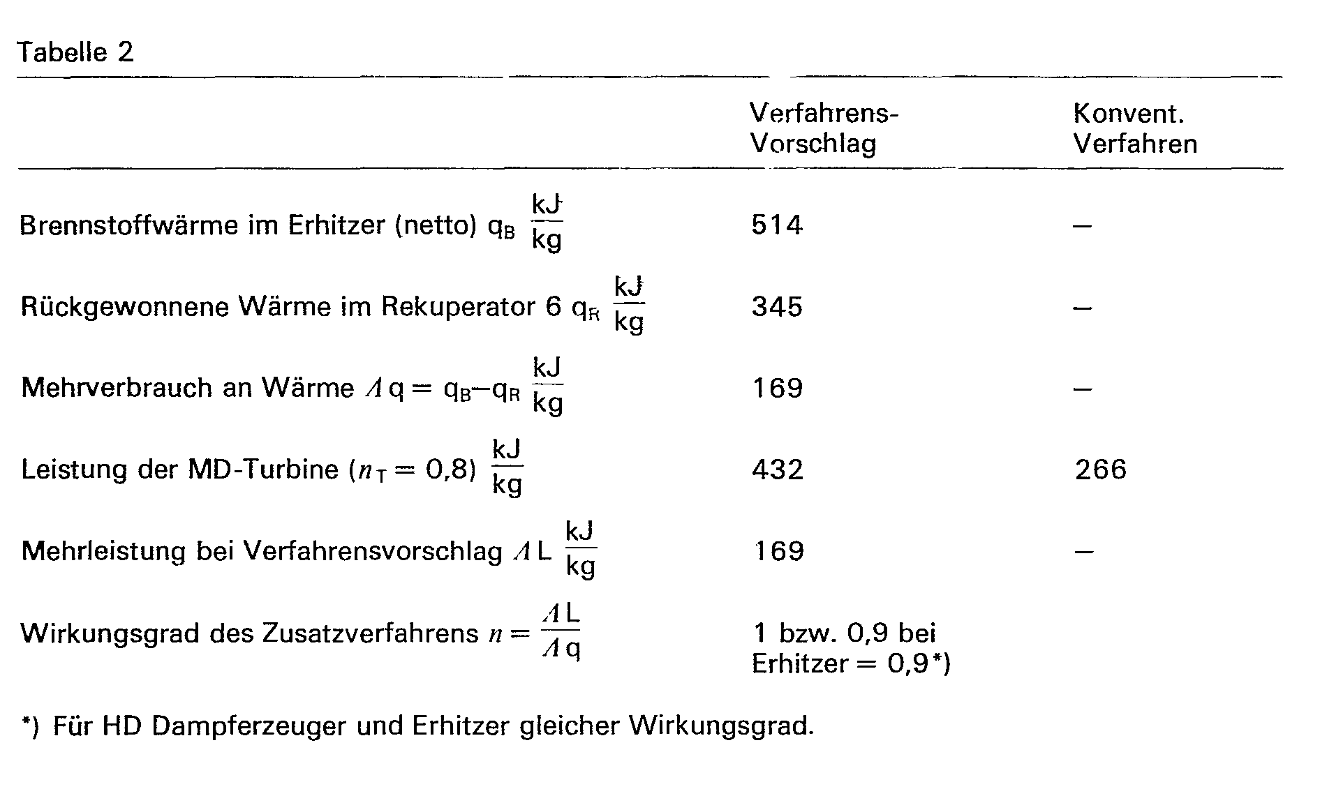
- Table 2 shows the specific consumption figures and outputs of the process example shown.
Landscapes
- Engineering & Computer Science (AREA)
- Chemical & Material Sciences (AREA)
- Combustion & Propulsion (AREA)
- Mechanical Engineering (AREA)
- General Engineering & Computer Science (AREA)
- Engine Equipment That Uses Special Cycles (AREA)
- Control Of Turbines (AREA)
Description
- Die Erfindung betrifft ein Verfahren zur Gewinnung von elektrischer Energie in einem Gegendruckdampfsystem, bei dem Wasserdampf arbeitsleistend entspannt wird.
- Als Gegendruckdampfsysteme werden hierbei Kraftanlagen bezeichnet, die zur gleichzeitigen Deckung des Kraft- und Wärmebedarfs dienen und eine umfassende Ausnutzung der Brennstoffwärme ermöglichen. In derartigen Systemen dient der in einem Dampfkessel erzeugte Wasserdampf hohen Druckes und hoher Temperatur zunächst dem Antrieb einer Hochdruckturbine, in der der Dampf in eine erste Dampfschiene auf eine geforderte Temperatur oder ein benötigtes Druckniveau entspannt wird. Aus dieser Dampfschiene kann nach bekannten Verfahren Dampf sowohl zur Deckung des Wärmebedarfs der Anlage abgezogen als auch in einer Turbine in eine andere Dampfschiene mit einem niedrigeren Druckniveau entspannt werden.
- Anlagen der angegebenen Art sind in »Linde-Berichte aus Technik und Wissenschaft« 38, 1976, Seiten 3 bis 8 beschrieben
- Bei kraftintensiven Industriezweigen kann der Bedarf an elektrischer oder auch mechanischer Energie durch eine Anlage der erläuterten Art nicht vollständig gedeckt werden. Dies ist beispielsweise bei dem Dampfsystem der im obengenannten Artikel beschriebenen Olefin- und Ammoniak-Anlagen der Fall. Es ist dahei erforderlich, zusätzlich Strom oder mechanische Energie in einem reinen Kraft-Prozeß mit verhältnismäßig unbefriedigender Primärbnergieausnutzung zu erzeugen oder teuren Fremdstrom zu beziehen.
- Eine derartige Anlage, in der ausschließlich mechanische bzw. elektrische Energie erzeugt wird, ist in der US-A-1 732 009 beschrieben. Hierbei wird in einem Verdampfer Wasser verdampft, der Dampf überhitzt, zweistufig entspannt und zwischen den Entspannungsstufen erneut erhitzt. Dabei wird der aus der ersten Entspannungsstufe austretende Dampf durch Dampf aus dem Verdampfer erhitzt Bei diesem Wärmetausch kühlt bzw. kondensiert der Dampf aus dem Verdampfer.
- Der Erfindung liegt daher die Aufgabe zugrunde, ein Verfahren zu entwickeln, mit dem in einem Gcgendruckdampfsystem der beschriebenen Art das Kraft-Wärme-Verhältnis erhöht werden kann.
- Diese Aufgabe wird erfindungsgemäß dadurch gelöst, daß Dampf eines der vorhandenen Druckniveaus vor der genannten arbeitsleistenden Entspannung zunächst durch Wärmetausch mit dem entspannten Dampf und anschließend mit Fremdwärme im wesentlichen isobar erhitzt und nach der genannten Entspannung auf eines der vorhandenen tiefer gelegenen Druckniveaus im wesentlichen isobar gekühlt wird.
- Wurde nach dem bekannten Verfahren Dampf einer Dampfmaschine einfach über eine Turbine auf eine Dampfschiene eines niedrigeren Druckniveaus entspannt, so wird der Dampf erfindungsgemäß zunächst rekuperativ durch Wärme des entspannten Dampfes und anschließend mit Fremdwärme, z. B. in einem Brennstoff befeuerten Erhitzer, nacherhitzt und erst dann, gegebenenfalls in mehreren Stufen, entspannt. Diesen Verfahrensschritten kann der Dampf jedes beliebigen der vorhandenen Druckniveaus unterzogen werden Auf dieser Weise wird der Anteil der in den Turbinen erzeugten mechanischen Energie und damit das Kraft-Wärme-Verhältnis erhöht. Dabei ist die Ausnutzung der Primärenergie für die Bereitstellung der Fremdwärme der bisherigen Zusatzstromerzeugung weit überlegen. Durch die rekuperative Erhitzung wird der Dampf auf eine relativ hohes Temperaturniveau gehoben, so daß die Fremdwärme, die dem Dampf nachfolgend zugeführt wird, optimal genutzt, d. h. auf sehr hohem Temperaturniveau aufgenommen wird. Da die Energieausbeute der zusätzlichen Energieerzeugung mit wachsender Temperatur des Dampfes vor der Entspannung steigt, ist eine möglichst hohe Temperatur des Dampfes wünschenswert. Die im Erhitzer erzielbare höchste Temperatur ist nur durch die Materialeigenschaften des Erhitzers begrenzt. Ein weiterer Vorteil der rekuperativen Erhitzung ist darin zu sehen, daß mit steigender Temperatur der Wärmequelle, durch die die Fremdwärme bereitgestellt wird, auch die Temperatur des der Wärmequelle zugeführten Dampfes wächst und somit die Wärme der Wärmequelle in allen Temperaturbereichen optimal genutzt wird. Bei einem idealen Gas und bei beliebig kleinen Temperaturdifferenzen beim rekuperativen Wärmetausch wäre die abgegebene Turbinenleistung gieich der aufgenommenen Fremdwärme.
- Die zusätzliche Energie des erfindungsgemäßen Verfahrens wird also mit einem wesentlich besseren Wirkungsgrad erzeugt, als etwa die durch einen reinen Kraft-Prozeß bereitgestellte Energie.
- Der entspannte Dampf besitzt nach der isobaren Kühlung noch immer einen höheren Wärmeinhalt als z. B. der nach einem konventionellen Verfahren nur in einer Turbine entspannte Dampf. Daher kann nach einer vorteilhaften Ausgestaltung des Erfindungsgedankens dieser Wärmeüberschuß zur Erwärmung eines Wärmeabnehmers verwendet werden. Als Wärmeabnehmer kann das zu erhitzende Arbeitsmedium eines zusätzlichen Kraftprozesses dienen. Es ist aber von Vorteil, den Wärmeüberschuß zur Speisewasservorwärmung des Gegendruckdampfsystems selbst heranzuziehen, da sich dann für das Zusatzverfahren unter Berücksichtigung der Verluste im Erhitzer ein Wirkungsgrad von 0,9 ergibt. In einer alternativen Verfahrensweise kann - mit dem gleichen Wirkungsgrad für das Zusatzverfahren - der Dampfdurchsatz des Gegendruckdampfsystems reduziert werden. Schließlich ist es möglich, den Wärmeüberschuß des entspannten und isobar gekühlten Dampfes direkt in eine Dampfschiene niedrigeren Druckniveaus zu leiten, d. h. den isobar gekühlten Dampf ohne weitere Kühlung mit einem Wärmeabnehmer direkt in diese Dampfschiene einzuspeisen.
- Insgesamt kann festgestellt werden, daß das erfindungsgemäße Verfahren die Erhöhung des Kraft-Wärmeverhältnisses innerhalb des Gegendruckbetriebes mit einem wesentlich besseren Wirkungsgrad als in konventionellen Verfahren ermöglicht. Wie beschrieben, ist der hohe Wirkungsgrad auf die dem höheren Temperaturniveau des Dampfes vor der Entspannung entsprechende höhere spezifische Energieerzeugung bzw. auf die Verringerung der erforderlichen Fremdwärme zurückzuführen. Werden in einer Anlage, die nach dem vorgeschlagenen Verfahren arbeitet, Kondensationsturbinen eingesetzt, verringert sich darüber hinaus im Vergleich zu herkömmlichen Anlagen mit Kondensationsturbinen die Kühlwassermenge, da infolge des erhöhten Kraft-Wärmeverhältnisses des Gegendruckbetriebes die Dampfmenge für die Kondensationsturbinen reduziert werden kann.
- Anhand einer schematischen Skizze soll im folgenden ein Ausführungsbeispiel einer Anlage beschrieben und erläutert werden, die nach dem erfindungsgemäßen Verfahren arbeitet.
- Der Übersichtlichkeit halber sind lediglich zwei Dampfschienen, eine Mitteldruckdampfschiene 15 und eine Niederdruckdampfschiene 16, dargestellt. Die Zahl der Damptschienen ist aber nicht auf zwei begrenzt.
- Der Dampf des dargestellten Gegendruckdampfsystems wird in einem Verdampfer 1 erzeugt, in einer Hochdruckturbine 2 auf einen Druck von z. B. 39,2 - 105N/mz entspannt und mit einer Temperatur von 642 K in die Mitteldruckdampfschiene eingespeist. In herkömmlichen Verfahren wurde der Dampf dieser Schiene, soweit er nicht von Wärmeabnehmern 11 verbraucht wurde, über eine Turbine direkt in die Niederdruckdampfschiene 16 entspannt. Erfindungsgemäß wird der Dampf jedoch zunächst im wesentlichen isobar erhitzt. Dazu dient ein Rekuperator 3, in dem ein Teil des Dampfes der Mitteldruckdampfschiene auf eine Temperatur von 770 K erhitzt, und ein brennstoffbefeuerter Erhitzer 4, in dem die Dampftemperatur auf 993 K gehoben wird. Der Dampf dieses hohen Temperaturniveaus wird in einer an den Erhitzer angeschlossenen Turbine 5 auf den Druck der Schiene 16 mit beispielsweise 9,8 - 105 N/m2 entspannt und zur isobaren Kühlung im Wärmetausch mit anzuwärmendem Dampf über Leitung 8 in den Rekuperator 3 eingeleitet. Die Temperatur des mit 791 K aus der Turbine austretenden Dampfes sinkt im Rekuperator 3 auf 653 K. Dieser Dampf besitzt im Vergleich mit der konventionellen Lösung einen höheren Wärmeinhalt. Dieser vvärmeüberschuß wird im dargestellten Ausführungsbeispiel im Wärmetausch mit Speisewasser für den Verdampfer 1 abgeführt. Dazu ist der Rekuperator 3 mit einem Wärmetauscher 6 verbunden, aus dem der Dampf mit 494 K aus- und in die Niederdruckdampfschiene 16 eintritt. Das Speisewasser wird dem Wärmetauscher 6 über eine Leitung 14, die von der Leitung 17 für die Kondensatrückführung abzweigt, zugeleitet und anschließend wieder in Leitung 17 eingespeist. Der Dampf der Niederdruckdampfschiene 16 wird Niederdruck-Prozeßdampf-Verbrauchern 10 zugeführt und kondensiert. Eine der Zahl der Dampfschienen entsprechende Zahl an Pumpen 12, 13 erhöht den Druck des Kondensats und versorgt den Dampfkessel 1 mit Speisewasser.
- In der folgenden Tabelle 1 sind Temperatur, Druck, spezifische Enthalpie und spezifische Entropie des Dampfes für das beschriebene Ausführungsbeispiel an den in der Skizze mit Buchstaben a bis f bezeichneten Stellen angegeben.
- In der Tabelle 2 sind die spezifischen Verbrauchszahlen bzw. Leistungen des dargestellten Verfahrensbeispiels aufgeführt.
- Wurde bei der konventionellen Lösung Dampf über eine zwischen die Dampfschienen 15 und 16 geschaltete Turbine entspannt, so konnte dieser Turbine pro kg Dampf eine Energie von 266 kJ entnommen werden. Erfindungsgemäß wird der Dampf der Mitteldruckdampfschiene erhitzt. Dazu werden im Erhitzer (4) 514 kJ pro kg Dampf übertragen. Im Rekuperator 6 werden davon 345 kJ pro kg rückgewonnen, so daß sich ein Mehrverbrauch von 169 kJ pro kg Dampf ergibt, da die im Rekuperator rückgewonnene Wärme Brennstoffwärme für den Verdampfer 1 ersetzt. Gegenüber der konventionellen Lösung liefert die Turbine pro kg Dampf 169 kJ (ohne Berücksichtigung des Erhitzerwirkungsgrades) mehr Energie. Der Wirkungsgrad des Zusatzverfahrens ist somit 1 bzw. 0,9, wenn der Erhitzerwirkungsgrad, der für den Verdampfer 1 und den Erhitzer 4 gleich sein soll, berücksichtigt wird.

Claims (3)
Applications Claiming Priority (2)
| Application Number | Priority Date | Filing Date | Title |
|---|---|---|---|
| DE2844742 | 1978-10-13 | ||
| DE19782844742 DE2844742A1 (de) | 1978-10-13 | 1978-10-13 | Verfahren zur gewinnung von elektrischer energie in einem gegendruckdampfsystem |
Publications (2)
| Publication Number | Publication Date |
|---|---|
| EP0010254A1 EP0010254A1 (de) | 1980-04-30 |
| EP0010254B1 true EP0010254B1 (de) | 1981-11-04 |
Family
ID=6052160
Family Applications (1)
| Application Number | Title | Priority Date | Filing Date |
|---|---|---|---|
| EP79103882A Expired EP0010254B1 (de) | 1978-10-13 | 1979-10-10 | Verfahren zur Gewinnung von elektrischer Energie in einem Gegendruckdampfsystem |
Country Status (6)
| Country | Link |
|---|---|
| US (1) | US4328675A (de) |
| EP (1) | EP0010254B1 (de) |
| JP (1) | JPS5591708A (de) |
| AT (1) | AT378038B (de) |
| CA (1) | CA1150955A (de) |
| DE (2) | DE2844742A1 (de) |
Families Citing this family (11)
| Publication number | Priority date | Publication date | Assignee | Title |
|---|---|---|---|---|
| US5622605A (en) * | 1993-11-05 | 1997-04-22 | Simpson; Gary D. | Process for desalinating water while producing power |
| JP3315800B2 (ja) * | 1994-02-22 | 2002-08-19 | 株式会社日立製作所 | 蒸気タービン発電プラント及び蒸気タービン |
| RU2166643C2 (ru) * | 1998-12-30 | 2001-05-10 | Закрытое акционерное общество "Завод "Киров-Энергомаш" - дочернее общество АО "Кировский завод" | Устройство утилизации перепада давлений в парогенерирующих системах |
| JP4486391B2 (ja) * | 2004-03-30 | 2010-06-23 | 株式会社神戸製鋼所 | 余剰蒸気の有効利用装置 |
| USRE46316E1 (en) * | 2007-04-17 | 2017-02-21 | Ormat Technologies, Inc. | Multi-level organic rankine cycle power system |
| US8438849B2 (en) * | 2007-04-17 | 2013-05-14 | Ormat Technologies, Inc. | Multi-level organic rankine cycle power system |
| EP2290200A1 (de) * | 2009-07-15 | 2011-03-02 | Siemens Aktiengesellschaft | Dampfkraftwerksanlage mit Dampfturbineneinheit und Prozessdampfverbraucher und Verfahren zum Betreiben einer Dampfkraftwerksanlage mit Dampfturbineneinheit und Prozessdampfverbraucher |
| US20110271676A1 (en) * | 2010-05-04 | 2011-11-10 | Solartrec, Inc. | Heat engine with cascaded cycles |
| US8789371B2 (en) * | 2011-01-03 | 2014-07-29 | General Electric Company | Power generation apparatus |
| CN104329127B (zh) * | 2014-11-10 | 2016-03-30 | 中国电力工程顾问集团华东电力设计院有限公司 | 多机组联合扩容系统 |
| PL3984983T3 (pl) * | 2020-10-13 | 2026-02-23 | Technische Universität München | Metanizacja z turbosprężarką |
Family Cites Families (9)
| Publication number | Priority date | Publication date | Assignee | Title |
|---|---|---|---|---|
| US1732009A (en) * | 1927-11-03 | 1929-10-15 | W S Garstow & Company | Method and apparatus for development of power |
| DE884802C (de) * | 1944-08-03 | 1953-07-30 | Rudolf Dipl-Ing Hingst | Dampfkraftanlage mit Zwischenueberhitzung |
| US2643519A (en) * | 1949-03-02 | 1953-06-30 | Richard C Powell | Regenerative steam power plant in which an extraction turbine supplies steam to desuperheaters which serve to heat feed water |
| DE1004203B (de) * | 1954-02-06 | 1957-03-14 | Siemens Ag | Heizkraftwerk mit Gegendruckturbine |
| US3376706A (en) * | 1965-06-28 | 1968-04-09 | Angelino Gianfranco | Method for obtaining mechanical energy from a thermal gas cycle with liquid phase compression |
| US3391539A (en) * | 1967-08-16 | 1968-07-09 | Gen Electric | Pressure control and flow dispatching system for steam turbine powerplant |
| US4178761A (en) * | 1977-06-17 | 1979-12-18 | Schwartzman Everett H | Heat source and heat sink pumping system and method |
| US4249384A (en) * | 1978-08-03 | 1981-02-10 | Harris Marion K | Isothermal compression-regenerative method for operating vapor cycle heat engine |
| US4214451A (en) * | 1978-11-13 | 1980-07-29 | Systems Control, Inc. | Energy cogeneration system |
-
1978
- 1978-10-13 DE DE19782844742 patent/DE2844742A1/de not_active Withdrawn
-
1979
- 1979-03-01 AT AT0156579A patent/AT378038B/de not_active IP Right Cessation
- 1979-10-10 EP EP79103882A patent/EP0010254B1/de not_active Expired
- 1979-10-10 DE DE7979103882T patent/DE2961270D1/de not_active Expired
- 1979-10-11 CA CA000337431A patent/CA1150955A/en not_active Expired
- 1979-10-11 JP JP13127179A patent/JPS5591708A/ja active Pending
- 1979-10-12 US US06/084,195 patent/US4328675A/en not_active Expired - Lifetime
Also Published As
| Publication number | Publication date |
|---|---|
| JPS5591708A (en) | 1980-07-11 |
| CA1150955A (en) | 1983-08-02 |
| AT378038B (de) | 1985-06-10 |
| ATA156579A (de) | 1984-10-15 |
| DE2961270D1 (en) | 1982-01-14 |
| EP0010254A1 (de) | 1980-04-30 |
| DE2844742A1 (de) | 1980-04-24 |
| US4328675A (en) | 1982-05-11 |
Similar Documents
| Publication | Publication Date | Title |
|---|---|---|
| EP1649147B1 (de) | Verfahren und vorrichtung zur ausführung eines thermodynamischen kreisprozesses | |
| EP1613841B1 (de) | Verfahren und vorrichtung zur ausführung eines thermodynamischen kreisprozesses | |
| EP3362739B1 (de) | Erzeugung von prozessdampf mittels hochtemperaturwärmepumpe | |
| DE69218206T2 (de) | Auf dem organischen rankine zyklus basierende energieanlage und verfahren zum betrieb der anlage | |
| DE102008045450B4 (de) | Verfahren zum Betreiben eines thermodynamischen Kreislaufes sowie thermodynamischer Kreislauf | |
| DE69407261T2 (de) | Methode und Vorrichtung zur Umwandlung von Wärme aus geothermischer Flüssigkeit und geothermischem Dampf in elektrische Energie | |
| DE10335143B4 (de) | Verfahren zur Erhöhung des Wirkungsgrades einer Gasturbinenanlage und dafür geeignete Gasturbinenanlage | |
| EP1549827A1 (de) | Verfahren und einrichtung zur rückgewinnung von energie | |
| EP1771641B1 (de) | Verfahren und vorrichtung zur übertragung von wärme von einer wärmequelle an einen thermodynamischen kreislauf mit einem arbeitsmittel mit zumindest zwei stoffen mit nicht-isothermer verdampfung und kondensation | |
| EP0010254B1 (de) | Verfahren zur Gewinnung von elektrischer Energie in einem Gegendruckdampfsystem | |
| DE102010060064A1 (de) | Verfahren zur Steigerung der Leistungsabgabe eines Gas- und Dampf-Kombikraftwerks während ausgewählter Betriebszeiträume | |
| EP0008680A2 (de) | Verfahren zur Erzeugung von Wärmeenergie durch Kombination der Kraft-Wärme-Kopplung mit der Wärmepumpe | |
| DE2201397A1 (de) | Verfahren und Vorrichtung zur regenerativen Vorwaermung bei Waermekraftwerken | |
| EP3559564A1 (de) | Verfahren und vorrichtung zur erzeugung von prozesskälte und prozessdampf | |
| EP1038094B1 (de) | Mehrstufiger dampfkraft-/arbeitsprozess für die elektroenergiegewinnung im kreisprozess sowie anordnung zu seiner durchführung | |
| DE102022128628A1 (de) | System und Verfahren zur Energiewandlung und Energiespeicherung | |
| EP3232023A1 (de) | Verfahren und anlage zur energieumwandlung von druckenergie in elektrische energie | |
| DE1906144A1 (de) | Waermekraftanlage fuer die Ausnutzung der in einem Kernreaktor erzeugten Waerme,mit einer kombinierten Gasturbinen-Dampfturbinenanlage | |
| EP2385223A1 (de) | Verfahren zur Steigerung des Wirkungsgrades von Gas- und Dampfturbinenanlagen | |
| DE2651888A1 (de) | Verfahren und vorrichtung zur nutzbarmachung von waerme eines waermetraegers niederer temperatur | |
| DE10355782A1 (de) | Vorrichtung und Verfahren zum Ausführen eines thermischen Kreisprozesses | |
| AT68741B (de) | Verfahren zur Verbindung eines Dampfkraftbetriebes von wechselndem Dampfverbrauche mit einem oder mehreren Abdampfverwertungsbetrieben. | |
| DE102010046584A1 (de) | Verfahren zur Erzeugung mechanischer / elektrischer Energie für niedrige Prozesstemperaturen | |
| DE2714179A1 (de) | Verfahren zur energieerzeugung mit einem geschlossenen kreislaufsystem | |
| DE102024123715A1 (de) | Wärmepumpenvorrichtung zur Dampf- und Wärmeerzeugung |
Legal Events
| Date | Code | Title | Description |
|---|---|---|---|
| PUAI | Public reference made under article 153(3) epc to a published international application that has entered the european phase |
Free format text: ORIGINAL CODE: 0009012 |
|
| AK | Designated contracting states |
Designated state(s): BE CH DE FR IT NL SE |
|
| 17P | Request for examination filed |
Effective date: 19801006 |
|
| ITF | It: translation for a ep patent filed | ||
| GRAA | (expected) grant |
Free format text: ORIGINAL CODE: 0009210 |
|
| AK | Designated contracting states |
Designated state(s): BE CH DE FR IT NL SE |
|
| REF | Corresponds to: |
Ref document number: 2961270 Country of ref document: DE Date of ref document: 19820114 |
|
| PGFP | Annual fee paid to national office [announced via postgrant information from national office to epo] |
Ref country code: SE Payment date: 19820930 Year of fee payment: 4 |
|
| PGFP | Annual fee paid to national office [announced via postgrant information from national office to epo] |
Ref country code: NL Payment date: 19821031 Year of fee payment: 4 |
|
| PGFP | Annual fee paid to national office [announced via postgrant information from national office to epo] |
Ref country code: CH Payment date: 19821231 Year of fee payment: 4 |
|
| PG25 | Lapsed in a contracting state [announced via postgrant information from national office to epo] |
Ref country code: SE Effective date: 19831011 |
|
| PG25 | Lapsed in a contracting state [announced via postgrant information from national office to epo] |
Ref country code: CH Effective date: 19831031 |
|
| PG25 | Lapsed in a contracting state [announced via postgrant information from national office to epo] |
Ref country code: NL Effective date: 19840501 |
|
| NLV4 | Nl: lapsed or anulled due to non-payment of the annual fee | ||
| REG | Reference to a national code |
Ref country code: CH Ref legal event code: PL |
|
| PGFP | Annual fee paid to national office [announced via postgrant information from national office to epo] |
Ref country code: FR Payment date: 19841009 Year of fee payment: 6 |
|
| PGFP | Annual fee paid to national office [announced via postgrant information from national office to epo] |
Ref country code: DE Payment date: 19841106 Year of fee payment: 6 |
|
| PGFP | Annual fee paid to national office [announced via postgrant information from national office to epo] |
Ref country code: BE Payment date: 19841231 Year of fee payment: 6 |
|
| PG25 | Lapsed in a contracting state [announced via postgrant information from national office to epo] |
Ref country code: BE Effective date: 19871031 |
|
| BERE | Be: lapsed |
Owner name: LINDE A.G. Effective date: 19871031 |
|
| PG25 | Lapsed in a contracting state [announced via postgrant information from national office to epo] |
Ref country code: FR Free format text: LAPSE BECAUSE OF NON-PAYMENT OF DUE FEES Effective date: 19880630 |
|
| PG25 | Lapsed in a contracting state [announced via postgrant information from national office to epo] |
Ref country code: DE Effective date: 19880701 |
|
| REG | Reference to a national code |
Ref country code: FR Ref legal event code: ST |
|
| EUG | Se: european patent has lapsed |
Ref document number: 79103882.1 Effective date: 19850607 |
|
| PLBE | No opposition filed within time limit |
Free format text: ORIGINAL CODE: 0009261 |
|
| STAA | Information on the status of an ep patent application or granted ep patent |
Free format text: STATUS: NO OPPOSITION FILED WITHIN TIME LIMIT |