EP0009253B1 - Retro-reflecting sheet material and method of manufacture - Google Patents
Retro-reflecting sheet material and method of manufacture Download PDFInfo
- Publication number
- EP0009253B1 EP0009253B1 EP79103558A EP79103558A EP0009253B1 EP 0009253 B1 EP0009253 B1 EP 0009253B1 EP 79103558 A EP79103558 A EP 79103558A EP 79103558 A EP79103558 A EP 79103558A EP 0009253 B1 EP0009253 B1 EP 0009253B1
- Authority
- EP
- European Patent Office
- Prior art keywords
- substrate
- retro
- beads
- layer
- reflector
- Prior art date
- Legal status (The legal status is an assumption and is not a legal conclusion. Google has not performed a legal analysis and makes no representation as to the accuracy of the status listed.)
- Expired
Links
- 239000000463 material Substances 0.000 title claims description 54
- 238000000034 method Methods 0.000 title claims description 37
- 238000004519 manufacturing process Methods 0.000 title description 5
- 239000011324 bead Substances 0.000 claims description 127
- 239000000758 substrate Substances 0.000 claims description 90
- 239000010410 layer Substances 0.000 claims description 66
- 239000011521 glass Substances 0.000 claims description 56
- 229910052751 metal Inorganic materials 0.000 claims description 52
- 239000002184 metal Substances 0.000 claims description 52
- 238000007373 indentation Methods 0.000 claims description 29
- 239000012780 transparent material Substances 0.000 claims description 21
- 239000000956 alloy Substances 0.000 claims description 20
- 229910045601 alloy Inorganic materials 0.000 claims description 19
- 229910052782 aluminium Inorganic materials 0.000 claims description 17
- XAGFODPZIPBFFR-UHFFFAOYSA-N aluminium Chemical group [Al] XAGFODPZIPBFFR-UHFFFAOYSA-N 0.000 claims description 17
- 239000011888 foil Substances 0.000 claims description 17
- 239000000853 adhesive Substances 0.000 claims description 14
- 230000001070 adhesive effect Effects 0.000 claims description 14
- 229910000838 Al alloy Inorganic materials 0.000 claims description 12
- 238000005096 rolling process Methods 0.000 claims description 12
- 239000002356 single layer Substances 0.000 claims description 11
- 238000003825 pressing Methods 0.000 claims description 9
- 229920001187 thermosetting polymer Polymers 0.000 claims description 7
- HCHKCACWOHOZIP-UHFFFAOYSA-N Zinc Chemical compound [Zn] HCHKCACWOHOZIP-UHFFFAOYSA-N 0.000 claims description 4
- 229910052725 zinc Inorganic materials 0.000 claims description 4
- 239000011701 zinc Substances 0.000 claims description 4
- 238000001035 drying Methods 0.000 claims description 2
- 239000004925 Acrylic resin Substances 0.000 claims 2
- 229920000178 Acrylic resin Polymers 0.000 claims 2
- 229910000914 Mn alloy Inorganic materials 0.000 claims 2
- 239000010953 base metal Substances 0.000 claims 2
- 241000206607 Porphyra umbilicalis Species 0.000 claims 1
- 238000000576 coating method Methods 0.000 description 22
- 239000011248 coating agent Substances 0.000 description 21
- 239000000123 paper Substances 0.000 description 11
- 239000000049 pigment Substances 0.000 description 7
- 230000004224 protection Effects 0.000 description 7
- 150000002739 metals Chemical class 0.000 description 6
- 239000004033 plastic Substances 0.000 description 6
- 229920003023 plastic Polymers 0.000 description 6
- 239000010408 film Substances 0.000 description 5
- 229920000642 polymer Polymers 0.000 description 5
- NIXOWILDQLNWCW-UHFFFAOYSA-N acrylic acid group Chemical group C(C=C)(=O)O NIXOWILDQLNWCW-UHFFFAOYSA-N 0.000 description 4
- 239000002904 solvent Substances 0.000 description 4
- 239000012790 adhesive layer Substances 0.000 description 3
- 230000000694 effects Effects 0.000 description 3
- 238000011068 loading method Methods 0.000 description 3
- 239000002344 surface layer Substances 0.000 description 3
- 239000004923 Acrylic lacquer Substances 0.000 description 2
- 239000002390 adhesive tape Substances 0.000 description 2
- 238000007605 air drying Methods 0.000 description 2
- 239000011230 binding agent Substances 0.000 description 2
- 230000015572 biosynthetic process Effects 0.000 description 2
- 238000010276 construction Methods 0.000 description 2
- 238000005336 cracking Methods 0.000 description 2
- -1 ferrous metals Chemical class 0.000 description 2
- 238000005065 mining Methods 0.000 description 2
- 239000002245 particle Substances 0.000 description 2
- 229920000728 polyester Polymers 0.000 description 2
- 230000009467 reduction Effects 0.000 description 2
- 238000002310 reflectometry Methods 0.000 description 2
- 229920005989 resin Polymers 0.000 description 2
- 239000011347 resin Substances 0.000 description 2
- 238000000926 separation method Methods 0.000 description 2
- 239000012815 thermoplastic material Substances 0.000 description 2
- XLYOFNOQVPJJNP-UHFFFAOYSA-N water Substances O XLYOFNOQVPJJNP-UHFFFAOYSA-N 0.000 description 2
- 239000002033 PVDF binder Substances 0.000 description 1
- 229910000831 Steel Inorganic materials 0.000 description 1
- ATJFFYVFTNAWJD-UHFFFAOYSA-N Tin Chemical compound [Sn] ATJFFYVFTNAWJD-UHFFFAOYSA-N 0.000 description 1
- 230000006750 UV protection Effects 0.000 description 1
- 238000003915 air pollution Methods 0.000 description 1
- 239000004411 aluminium Substances 0.000 description 1
- 230000002238 attenuated effect Effects 0.000 description 1
- 230000008901 benefit Effects 0.000 description 1
- 238000005253 cladding Methods 0.000 description 1
- 238000012790 confirmation Methods 0.000 description 1
- 238000010924 continuous production Methods 0.000 description 1
- 239000011162 core material Substances 0.000 description 1
- 238000010586 diagram Methods 0.000 description 1
- 238000006073 displacement reaction Methods 0.000 description 1
- 239000000839 emulsion Substances 0.000 description 1
- 238000005516 engineering process Methods 0.000 description 1
- 238000003912 environmental pollution Methods 0.000 description 1
- 229920006334 epoxy coating Polymers 0.000 description 1
- 238000007765 extrusion coating Methods 0.000 description 1
- 238000011049 filling Methods 0.000 description 1
- NBVXSUQYWXRMNV-UHFFFAOYSA-N fluoromethane Chemical compound FC NBVXSUQYWXRMNV-UHFFFAOYSA-N 0.000 description 1
- 238000009472 formulation Methods 0.000 description 1
- 230000003760 hair shine Effects 0.000 description 1
- 239000002655 kraft paper Substances 0.000 description 1
- 239000004922 lacquer Substances 0.000 description 1
- 238000010030 laminating Methods 0.000 description 1
- 239000011133 lead Substances 0.000 description 1
- 238000005259 measurement Methods 0.000 description 1
- 230000007246 mechanism Effects 0.000 description 1
- 238000002844 melting Methods 0.000 description 1
- 230000008018 melting Effects 0.000 description 1
- 239000000203 mixture Substances 0.000 description 1
- 230000003287 optical effect Effects 0.000 description 1
- 239000011368 organic material Substances 0.000 description 1
- 238000000643 oven drying Methods 0.000 description 1
- 239000002985 plastic film Substances 0.000 description 1
- 229920006255 plastic film Polymers 0.000 description 1
- 229920000058 polyacrylate Polymers 0.000 description 1
- 229920006254 polymer film Polymers 0.000 description 1
- 229920001296 polysiloxane Polymers 0.000 description 1
- 229920002620 polyvinyl fluoride Polymers 0.000 description 1
- 229920002981 polyvinylidene fluoride Polymers 0.000 description 1
- 238000002360 preparation method Methods 0.000 description 1
- 230000008569 process Effects 0.000 description 1
- 230000011514 reflex Effects 0.000 description 1
- 239000007921 spray Substances 0.000 description 1
- 238000003892 spreading Methods 0.000 description 1
- 230000007480 spreading Effects 0.000 description 1
- 239000010959 steel Substances 0.000 description 1
- 239000000126 substance Substances 0.000 description 1
- 230000001360 synchronised effect Effects 0.000 description 1
- 229920001169 thermoplastic Polymers 0.000 description 1
- 239000004634 thermosetting polymer Substances 0.000 description 1
- 239000010409 thin film Substances 0.000 description 1
- 239000011135 tin Substances 0.000 description 1
- 229910052718 tin Inorganic materials 0.000 description 1
Images


Classifications
-
- B—PERFORMING OPERATIONS; TRANSPORTING
- B29—WORKING OF PLASTICS; WORKING OF SUBSTANCES IN A PLASTIC STATE IN GENERAL
- B29D—PRODUCING PARTICULAR ARTICLES FROM PLASTICS OR FROM SUBSTANCES IN A PLASTIC STATE
- B29D11/00—Producing optical elements, e.g. lenses or prisms
- B29D11/00605—Production of reflex reflectors
- B29D11/00615—Production of reflex reflectors moulded by partially embedding reflective elements, e.g. glass beads, into the surface of a support, e.g. to make prefabricated road markings
-
- G—PHYSICS
- G02—OPTICS
- G02B—OPTICAL ELEMENTS, SYSTEMS OR APPARATUS
- G02B5/00—Optical elements other than lenses
- G02B5/12—Reflex reflectors
- G02B5/126—Reflex reflectors including curved refracting surface
- G02B5/128—Reflex reflectors including curved refracting surface transparent spheres being embedded in matrix
Definitions
- This invention relates to retro-reflective sheet material (also known as reflex reflectors) and to a method of preparing the same.
- Retro-reflective material is well known and widely used in the prior art, mainly in connection with road signs and automobile licence plates and the like.
- the material is capable of reflecting an incident beam of light back in the general direction of the light source.
- a car headlight illuminates a road sign bearing such material in otherwise dark surroundings, the sign reflects a greater amount of light towards the driver than surrounding objects and is therefore clearly visible.
- the retroreflective materials fall into two general types.
- the first type consists of spherical glass beads adhered to the surface of a transparent organic coating applied over a reflective metal (or other) substrate but only partially imbedded in it so that a glass-air interface is presented to incoming light.
- This type of material does not function as a retro-reflector when the surface is wet with water.
- the second type of material consists of high refractive index (about 1.9 and greater) glass beads suspended within a relatively thick film of a transparent organic coating (plastic film) applied over a reflective metal substrate. Such material retains its retro-reflective properties when wet.
- the most effective retro-reflectors of the second type can be formed by positioning the glass beads at just the right distance from conforming segments of concave spherical mirrors of corresponding size located behind the individual beads. This optimum distance will vary depending on the diameter of the beads, their refractive index, and the refractive index of the medium in which they are suspended.
- Various known retroreflectors embody such a structure but have generally been produced in the form of flexible tapes or sheets which are adhered to the desired object, such as a road sign.
- the step of adhering the tape to the object can be time consuming and uneconomical, and the tape may peel from the object after a period of exposure to the elements.
- U.S. Patent No. 2,543,800 issued on March 6, 1951 and assigned to Minnesota Mining and Manufacturing Company discloses a retro-reflector in which a monolayer of beads of high refractive index is partially pressed into a moldable cushion layer having a reflective surface coating containing metallic flake pigment particles, the beads being spaced from the cushion layer by a thin film which may contain a transparent pigment and is preferably of a thickness less than 1/10 of the diameter of the beads.
- the beads are further bonded to the cushion layer by a transparent binder layer and may be covered by a transparent covering layer having a flat front face applied to the beads after the latter have been pressed into the cushion layer. After the pressing operation or operations the plastic layers are cured.
- One disadvantage of such retro-reflectors is that the reflector surfaces formed by the cushion layer are not as reflective as a polished metal surface and therefore light is lost at these surfaces.
- U.S. Patent 3,922,433 issued on November 25, 1975 and assigned to Aluminum Company of America relates to partially embedding the spherical glass beads into a metallic coating while it is in the molten condition.
- This invention is an attempt to form a retro-reflective surface directly on a substrate made of a hard material, such as a road sign, without first forming a flexible tape to be adhered thereto.
- An iron-base substrate is dipped into a molten bath of aluminum, zinc, tin, lead or alloys thereof and is sprayed with the glass beads by an air gun as the substrate is withdrawn from the bath and the coating is still molten.
- This method has the disadvantages that it is expensive and the beads are not spaced from the reflective surface as is required for the optimum retro-reflection.
- a product of high quality can be produced by indenting the substrate surface by applying pressure to the glass beads when a platen is located between the surface of the layer containing the glass beads and a roller or the like used for applying said pressure.
- a method of preparing a retro- reflective surface on a substrate comprising providing a layer of transparent material on said surface of the substrate, adhering a mono layer of glass beads of refractive index to said transparent material, applying pressure to said glass beads to cause the beads to indent the surface of the substrate, and applying a further layer of transparent material over said glass beads, characterized in that said substrate, at least at the surface to be indented, is made of an indentable metal, and said pressure is applied to the beads via a platen overlying said beads.
- a retro-reflector comprising a substrate having a surface, transparent material overlying said surface of said substrate, a mono layer of glass beads of high refractive index adhered to said transparent material, and a further layer of transparent material overlying said layer of glass beads, said surface of said substrate having indentations conforming to the adjacent glass beads and the separation of the glass beads from the substrate surface by said layer of transparent material being suitable for retro-reflection, characterized in that said substrate, at least at said surface thereof, is made of an indentable metal.
- the effectiveness of the platen is quite unexpected because the damage to the glass beads and misalignment of the beads with the conforming convex mirrors encountered in original attempts to form retro-reflective surfaces on hard substrates was believed to be due to the load required to force each bead to indent the substrate material via the intervening polymer layer. If a platen is used, the beads must be subject to the same loading in order to cause proper indentation, so it was unreasonable to expect a platen to prevent damage to the beads.
- the platen may take the form of any resilient or deformable material having substantially no tendency to adhere to the glass beads during the indentation step.
- the material of the platen should be sufficiently soft to be indented either elastically or plastically by the glass beads during the indenting step, but of course should be capable of transmitting sufficient force to the beads to cause the necessary indentation of the substrate.
- the platen may be a plate or sheet of aluminum or other metal. It has also unexpectedly been found that the platen can be a thin foil or web of metal or paper or similar material. Such thin foils or webs are particularly advantageous because they can be withdrawn from a roll of the material and passed virtually continuously through a roll mill with the beaded substrate. This makes the manufacture of the retro-reflective substrate economical particularly as the foil or wel-like platens are themselves inexpensive.
- indentable metal substrate is used throughout this specification to refer to those substrates which can be used in the method of the invention, i.e., those having a hardness below the practical maximum hardness limit in the particular operating conditions.
- Very hard metals can be provided with a retro-reflective surface if the hard metals are first coated or "clad” with a softer metal because only the hardness of the surface layer of the substrate is important in the indentation step.
- the term “indentable metal substrate” therefore includes such structures.
- transparent is used in a wide sense throughout this specification and is intended to include materials that are sometimes referred to as semi-transparent. The important point is that the various layers overlying the substrate, and even the glass beads themselves, must be capable of transmitting sufficient light for the structure to function effectively as a retro-reflector. Any layer or material (e.g. pigment or dye) capable of transmitting sufficient light to achieve this function is considered to be “transparent” in the context of this invention.
- a metal substrate having a retro-reflective surface can be prepared without carrying out the disadvantageous steps of first forming an adhesive tape having the retro-reflective characteristics followed by adhering the tape to the substrate.
- the indentable metal substrate is preferably first coated with a transparent layer of an organic polymeric material and the layer is allowed to harden or is cured. A second layer of an organic material is then applied as an adhesive material. Small glass beads are applied to the adhesive surface to form a mono-layer, the beads being as densely packed on the surface as possible. The adhesive is allowed to harden or is cured.
- the transparent organic polymeric material it is also possible to combine in one layer the functions of space coat and adhesive.
- the first layer is partially dried or cured to a degree at which the glass beads applied to the surface will adhere to form a monolayer but will not sink excessively into the polymeric material before it can be completely cured or dried. Thus the required separation between beads and substrate is preserved.
- the structure thus formed in either one of the alternative methods above is pressed in a mill so that the surface of the metal substrate is indented by the glass beads. Although the glass beads cause the metal substrate to form indentations, the beads themselves do not directly contact the substrate and remain spaced therefrom by the polymer layer. The pressure applied to the beads during the indentation step is thus transmitted to the substrate layer via the polymer layer and is sufficient to cause concave deformations to form in the substrate metal.
- a platen prevents damage to the retro-reflective structure but this may be because the platen acts as a cushion and, by spreading out the load, reduces the unit pressure on the glass bead surfaces. Alternately, or in addition, the platen may avoid the relative motion between the beads and the pressure roll, or the like, which exists when no platen is used. Whichever mechanism is effective, the requirement for a platen was quite unexpected and its effectiveness in preventing damage to the glass beads and polymer layers is remarkable.
- the glass beads are covered with one or more layers of a transparent organic polymeric material and the polymeric material is cured or allowed to harden.
- the extra layer or layers protect the glass beads and provides a flat outer surface. If there is no overlying layer, a structure of the first type mentioned earlier would be produced which would lose its retroreflective properties when wet with water.
- any one of the layers of organic polymeric material may contain a pigment or dye in order to impart a colour to the retro-reflective surface.
- the pigment or dye should preferably be light fast and not heat sensitive. Clear pigments give the best results, although any stable type of pigment or dye can be employed provided the resulting pigmented layer remains transparent in the sense defined earlier in this specification.
- the indentable metal substrates are usually metals suitable for preparing objects such as road signs and markers and automobile licence plates. Softer metals are preferred in order to reduce the pressures required in the indentation step.
- Aluminum is the preferred material, although zinc-coated iron-base material has also proved very effective.
- the preferred aluminum alloys are soft alloys such as AA1100, although harder alloys like Alcan SW-30 (an AI- 1/2% Mn type alloy) and AA5454 (having a hardness of 85 BHN) can also be used.
- angles of incidence at which retro-reflectivity takes place may be reduced to some extent when harder substrates are employed because of reduced indentation of the metal, it may be desirable in those applications where a very hard aluminum substrate is required to employ a clad substrate, i.e., a hard aluminum alloy as a core material and a softer alloy as a cladding.
- the glass beads preferably have diameters in the range 50 to 80 microns and are of high refractive index e.g., 1.9 and higher. Glass beads obtainable from Flex-O-Lite Division of General Steel Industries Limited, St. Louis, U.S.A. under the designation Type 910-18 are found to be useful. These beads have diameters of about 75 microns and a refractive index of 2.1.
- Type 831 refractive index 1.9
- Type 938 refractive index 2.28
- Fol Glass 1020 refractive index 2.24
- the size of the beads is also a factor in determining the thickness of the space coat. For example:
- thermosetting polymers are more likely to have the toughness to withstand the pressing operation than thermoplastic polymers.
- An example is a thermosetting acrylic coating sold under the trade mark DURACRON 100 by Canadian Pittsburgh Industries Ltd. The same material or a different material can be used to form the other transparent layers of the product.
- the first layer should be hard and not susceptible to crazing, cracking or excessive attenuation during the indentation step, whereas the layers overlying the beads applied after the indentation step (top coat) need not be as hard but preferably should be able to release their solvent without "popping", i.e., the polymeric material should preferably have a smooth surface when dry.
- the transparent adhesive layer is usually quite soft so that it flows upwardly around the beads to some extent during the indentation step thus leaving the tops of the beads less proud from the surface than before the application of pressure. Only a relatively thin top coat is then required to cover the tops of the beads and to form a smooth outer surface. The requirement for a thin top coat is preferred because thinner coats are less prone to "solvent popping" than thicker coats.
- an adhesive layer it should preferably be as thin as possible to reduce any tendency of the glass beads to form more than a single layer on the adhesive surface.
- the indentation step can be carried out in a press mill or a roller mill, but a roller mill is preferred because this lends itself more readily to continuous processes. Moreover, greater loads are required when the pressure is applied statically because the area of contact is much greater than in a rolling mill. The pressure required is dictated to a large extent by the hardness of the substrate material, and the minimum pressure capable of producing satisfactory indentation is preferable because higher pressures merely increase the possibility of fracture of the beads or polymer layer. In the case of a mill having 4 inch diameter rolls, the loading of the mill usually falls within the range of 1400 to 7900 N/cm of substrate width.
- the platen may take the form of a sheet of metal, e.g., aluminium, or may be a web of paper or a metal foil such as aluminum foil. Any suitable type of paper or metal foil can be employed, although plastic coated papers should preferably be avoided because the plastic may tend to adhere to the glass particles or press rolls.
- plastic coated papers should preferably be avoided because the plastic may tend to adhere to the glass particles or press rolls.
- the process can readily be made continuous.
- known coil coating techniques can be employed and the platen can be supplied to the press rollers from a large roll or the like and can be rewound after passing through the press for disposal or re-use.
- the surface of the indentable metal substrate should preferably be bright before the application of the space coat so that the metal surface forms a good reflector.
- the indentation step results in the formation of bright new metal surfaces within the concave indentations.
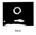
- a light source 1 e.g., a photoflood lamp or a spot lamp, shines through a circular aperture having a diameter of 5 cm onto a 10 cm square sample 3 of retro-reflective material.
- the aperture serves to define the area illuminated and to block out stray light from behind the sample.
- the sample is mounted on the axle of a synchronous motor 4 which causes the sample to rotate at 1 rev/minute.
- Light reflected by the sample in the direction of the light source 1 is caused to fall on a photocell 5.
- the light source and photocell are mounted 6 metres away from the aperture 2, and the photocell is protected from extraneous light sources by a cardboard cylinder 6.
- the output of the cell is recorded on a suitable pen recorder 7.
- the sample To measure the intensity of retro-reflected light the sample is set rotating and the output of the photocell recorded. Zero retro-reflectivity is taken as the light intensity when the sample is perpendicular to the aperture.
- the back of the sample holder is a specular reflector which can be used to calibrate the chart speed of the recorder with sample angle. Since small changes in optical alignment affect the intensity measurement, a standard reflector sheet is measured for each set of samples.
- the samples were made by first applying (by drawdown) a base coat of DURACRON 100 (Trade Mark) on panels of unpretreated mill finish Alcan SW-30 aluminum alloy sheet 0.56 mm thick, and curing it at 260°C for 2 minutes. A second very thin adhesive coating of DURACRON 100 (Trade Mark) was then applied, allowed to partially dry for about 30 seconds at 205°C., and then "beaded” by dropping on it a copious quantity of the Flex-O-Lite (Trade Mark) beads and shaking off those which did not adhere. This procedure produced a single densely populated layer of beads adhering to, and partially embedded in, the surface. The adhesive coat holding the beads was then cured for 2 minutes at 260°C.
- a panel of the same aluminum sheet of corresponding size was laid over the beaded surface as a platen and the assembly passed through a sheet rolling mill for a nominal reduction of about 2 percent at a load of about 5800 N/cm of sample width.
- the platen was then removed and one or more top coats of DURACRON 100 (Trade Mark) were applied and cured for two minutes at 260°C., thus filling in the interstices between the partially imbedded beads and providing a transparent top coat over them.
- the aluminum substrate has been distorted into conformity with the beads without the base coat having been broken or significantly thinned. That is, the spacing has been maintained while enough conformity has been introduced to make the difference between high and low quality reflectors.
- retro-reflective layers were formed in a similar manner to Example 1 on the following substrate metals as noted in Table 2 below and were rolled with the platens and at the pressures also noted in the Table.
- This Example shows that the harder alloys required for road signs and the like can be made directly retro-reflective by the method of the present invention.
- Figs. 6 to 10 show the retro-reflective properties of these samples compared with those of a commercial grade prior art tape. In the case of some of the alloys, higher intensity of reflection than the prior art tape can be achieved with some sacrifice of reflection at the larger angles.
- samples were prepared from Alcan SW-30 aluminum alloy and AA5454 H-36 aluminum alloy starting with a 12.7 cm x 30.5 cm x 1.295 mm sheet of the alloy material.
- step (b) was kept as thin as possible to avoid any "second layer” beads adhering to the samples.
- the samples were each rolled in the 10.2 cm mill with the platen arranged to cover only half the surface of each sample.
- Photomicrographs were made of both surface areas and also of the cross sections. In all cases, the area rolled without the platen showed fractured beads, while the panel area protected by the platen showed the beads intact.
- the samples were rolled using platens of different weight and quality of paper and foil to determine their effect on the retro-reflective properties.
- the alloy used for the samples was Alcan SW-30 (H-15 temper, 0.584 mm thick).
- the thickness of the coating between the beads and the substrate was 8 ym.
- the beads had a refractive index of 2.28 and the rolling mill load applied was 4900 N/cm of sample width.
- a pretreated panel of Alcan SW-30 aluminum (size 10.2 cm x 25.4 cm x 0.559 mm) was coated with 8 ym of clear thermosetting acrylic lacquer and cured.
- a second coat of 8 ,um acrylic served as an adhesive for the glass beads having a refractive index of 2.28 (size 53 to 63 ,um) which were dusted on the adhesive layer to form a single, densely populated layer.
- the beaded panel was then cured.
- Aluminum foil (0.041 mm thick) of the same size as the panel was placed on top of the beaded surface and fed into a rolling mill loaded sufficiently to produce a 2% reduction in thickness at a load of about 5800 N/cm of sample width.
- the panel was removed and was coated with 25,um of clear acrylic lacquer.
- the retro-reflective properties of the beaded coated sheet thus produced (designated sample 526) are shown in Fig. 19 and compared with two commercially available retro-reflective tapes.
Landscapes
- Engineering & Computer Science (AREA)
- Physics & Mathematics (AREA)
- Health & Medical Sciences (AREA)
- Manufacturing & Machinery (AREA)
- Ophthalmology & Optometry (AREA)
- Mechanical Engineering (AREA)
- General Physics & Mathematics (AREA)
- Optics & Photonics (AREA)
- Optical Elements Other Than Lenses (AREA)
- Road Signs Or Road Markings (AREA)
- Illuminated Signs And Luminous Advertising (AREA)
- Laminated Bodies (AREA)
Priority Applications (1)
| Application Number | Priority Date | Filing Date | Title |
|---|---|---|---|
| CA311,780A CA1109308A (en) | 1979-09-20 | 1978-09-21 | Retro-reflecting sheet material |
Applications Claiming Priority (2)
| Application Number | Priority Date | Filing Date | Title |
|---|---|---|---|
| CA311780 | 1978-09-21 | ||
| CA311,780A CA1109308A (en) | 1979-09-20 | 1978-09-21 | Retro-reflecting sheet material |
Publications (2)
| Publication Number | Publication Date |
|---|---|
| EP0009253A1 EP0009253A1 (en) | 1980-04-02 |
| EP0009253B1 true EP0009253B1 (en) | 1984-03-21 |
Family
ID=4112408
Family Applications (1)
| Application Number | Title | Priority Date | Filing Date |
|---|---|---|---|
| EP79103558A Expired EP0009253B1 (en) | 1978-09-21 | 1979-09-20 | Retro-reflecting sheet material and method of manufacture |
Country Status (8)
| Country | Link |
|---|---|
| US (2) | US4265938A (no) |
| EP (1) | EP0009253B1 (no) |
| JP (1) | JPS5544899A (no) |
| AU (1) | AU525826B2 (no) |
| BR (1) | BR7906008A (no) |
| DE (1) | DE2966829D1 (no) |
| ES (2) | ES8101927A1 (no) |
| NO (1) | NO154779C (no) |
Families Citing this family (27)
| Publication number | Priority date | Publication date | Assignee | Title |
|---|---|---|---|---|
| US4609587A (en) * | 1984-11-30 | 1986-09-02 | Potters Industries, Inc. | Retroreflective materials and use |
| US4756931A (en) * | 1984-11-30 | 1988-07-12 | Potters Industries, Inc. | Retroreflective materials and methods for their production and use |
| US4772511A (en) * | 1985-11-22 | 1988-09-20 | Minnesota Mining And Manufacturing Company | Transparent non-vitreous zirconia microspheres |
| US4814960A (en) * | 1986-05-14 | 1989-03-21 | Liu P Dong Guang | Glare control |
| US4907360A (en) * | 1987-07-30 | 1990-03-13 | Macmunn William G | Three-dimensional signage |
| US5073005A (en) * | 1988-05-02 | 1991-12-17 | Hubbs Machine & Manufacturing | Retro-reflective photogrammetric target |
| US5039200A (en) * | 1989-06-21 | 1991-08-13 | Linda Michler | Reflective safety stick for walking and jogging |
| US5410212A (en) * | 1993-04-01 | 1995-04-25 | General Electric Company | Soft white reflector lamp |
| NO301797B1 (no) * | 1995-12-22 | 1997-12-08 | Norsk Hydro As | Retroreflekterende platemateriale og fremgangsmåte for fremstilling av slikt materiale |
| US5736602A (en) * | 1996-04-09 | 1998-04-07 | Crocker; George L. | Retroreflective coating composition for coil coating application, method for application, and articles produced therefrom |
| US6132861A (en) * | 1998-05-04 | 2000-10-17 | 3M Innovatives Properties Company | Retroreflective articles including a cured ceramer composite coating having a combination of excellent abrasion, dew and stain resistant characteristics |
| US6245833B1 (en) | 1998-05-04 | 2001-06-12 | 3M Innovative Properties | Ceramer composition incorporating fluoro/silane component and having abrasion and stain resistant characteristics |
| US6265061B1 (en) | 1998-05-04 | 2001-07-24 | 3M Innovative Properties Company | Retroflective articles including a cured ceramer composite coating having abrasion and stain resistant characteristics |
| US6352758B1 (en) | 1998-05-04 | 2002-03-05 | 3M Innovative Properties Company | Patterned article having alternating hydrophilic and hydrophobic surface regions |
| KR100429098B1 (ko) * | 1998-12-09 | 2004-04-29 | 가부시키가이샤 도모에가와 세이시쇼 | 필러 렌즈 및 그 제조방법 |
| ES2267545T3 (es) | 1999-05-26 | 2007-03-16 | Basf Corporation | Provision de ripias metalicas para techado y metodo de fabricacion. |
| WO2002013978A2 (en) * | 2000-08-16 | 2002-02-21 | Daniel Mushett | Process for forming a reflective surface |
| AU2003277661C1 (en) * | 2002-11-27 | 2005-12-08 | Kiwa Chemical Industry Co., Ltd. | Retroreflective Sheet |
| FR2869040B1 (fr) * | 2004-04-14 | 2006-05-26 | Sunis Sa Sa | Composition retro-reflechissante |
| FR2869041B1 (fr) * | 2004-04-14 | 2006-12-22 | Sunis Sa Sa | Compositions retro reflechissantes pour equipements de securite |
| US7874686B2 (en) * | 2004-09-27 | 2011-01-25 | Brainlab Ag | Reflective marker and method for its manufacture |
| US7698826B2 (en) * | 2007-02-12 | 2010-04-20 | Hubbs Machine & Manufacturing Co. | Refurbishable retro-reflective photogrammetric target |
| US20100000977A1 (en) * | 2008-07-07 | 2010-01-07 | Ashok Sudhakar | Method for removal of content-based stripe and the like on a substrate and equipment thereof |
| DE102009019986B8 (de) | 2009-05-06 | 2013-08-01 | Ilumark Gmbh | Retro-reflektierender Marker |
| US9082062B2 (en) | 2011-10-10 | 2015-07-14 | Zortag, Inc. | Method of, and system and label for, authenticating objects in situ |
| US8915045B2 (en) | 2013-02-21 | 2014-12-23 | EML Products Inc. | Sleeves for sign posts |
| CN115798351B (zh) * | 2022-12-19 | 2023-12-01 | 淮安惠铭光学材料有限公司 | 一种玻璃微珠密封胶囊型车身反光标识及其加工工艺 |
Citations (1)
| Publication number | Priority date | Publication date | Assignee | Title |
|---|---|---|---|---|
| US3473952A (en) * | 1966-09-19 | 1969-10-21 | Minnesota Mining & Mfg | Fluorocarbon polymer release coating |
Family Cites Families (12)
| Publication number | Priority date | Publication date | Assignee | Title |
|---|---|---|---|---|
| DE70C (de) * | 1877-08-07 | H. SCHMIDT, Ingenieur in Cüstrin | Dampfkessel aus Ringen von U-förmig gewalztem Eisen und mit dem Feuer entzogener Nietung | |
| US2407680A (en) * | 1945-03-02 | 1946-09-17 | Minnesota Mining & Mfg | Reflex light reflector |
| US2543800A (en) * | 1947-12-05 | 1951-03-06 | Minnesota Mining & Mfg | Reflex light reflector |
| US3279316A (en) * | 1962-03-26 | 1966-10-18 | California Metal Enameling Com | Reflex reflecting article for use as a sign or the like |
| GB1081601A (en) * | 1963-08-07 | 1967-08-31 | Minnesota Mining & Mfg | Reflex reflecting sheets and articles |
| US3355311A (en) * | 1963-10-22 | 1967-11-28 | Pittsburgh Plate Glass Co | Reflective coatings |
| US3405025A (en) * | 1965-06-17 | 1968-10-08 | Canrad Prec Ind Inc | Retro-reflective assembly and method of making the same |
| US3413168A (en) * | 1967-05-03 | 1968-11-26 | Minnesota Mining & Mfg | Adhesive bonding method permitting precise positioning |
| US3473052A (en) * | 1968-05-08 | 1969-10-14 | Rca Corp | System for producing indications of time relationship of electrical signals |
| AT307280B (de) * | 1969-05-09 | 1973-05-10 | Swarovski & Co | Reflexfolie und Verfahren zu ihrer Herstellung |
| US3922433A (en) * | 1971-03-01 | 1975-11-25 | Aluminum Co Of America | Aluminous metal with glass beads bonded to a metal substrate |
| JPS50102288A (no) * | 1974-01-09 | 1975-08-13 |
-
1979
- 1979-09-13 US US06/075,007 patent/US4265938A/en not_active Expired - Lifetime
- 1979-09-20 EP EP79103558A patent/EP0009253B1/en not_active Expired
- 1979-09-20 BR BR7906008A patent/BR7906008A/pt unknown
- 1979-09-20 ES ES484322A patent/ES8101927A1/es not_active Expired
- 1979-09-20 NO NO793015A patent/NO154779C/no unknown
- 1979-09-20 DE DE7979103558T patent/DE2966829D1/de not_active Expired
- 1979-09-20 AU AU50987/79A patent/AU525826B2/en not_active Ceased
- 1979-09-21 JP JP12250579A patent/JPS5544899A/ja active Granted
-
1980
- 1980-04-28 ES ES490980A patent/ES490980A0/es active Granted
- 1980-10-27 US US06/201,156 patent/US4340273A/en not_active Expired - Lifetime
Patent Citations (1)
| Publication number | Priority date | Publication date | Assignee | Title |
|---|---|---|---|---|
| US3473952A (en) * | 1966-09-19 | 1969-10-21 | Minnesota Mining & Mfg | Fluorocarbon polymer release coating |
Non-Patent Citations (1)
| Title |
|---|
| DE B F 470 VIIIb/74d * |
Also Published As
| Publication number | Publication date |
|---|---|
| US4340273A (en) | 1982-07-20 |
| NO793015L (no) | 1980-03-24 |
| ES484322A0 (es) | 1980-12-16 |
| US4265938A (en) | 1981-05-05 |
| DE2966829D1 (en) | 1984-04-26 |
| ES8103669A1 (es) | 1981-03-16 |
| ES8101927A1 (es) | 1980-12-16 |
| NO154779C (no) | 1987-01-02 |
| AU525826B2 (en) | 1982-12-02 |
| ES490980A0 (es) | 1981-03-16 |
| EP0009253A1 (en) | 1980-04-02 |
| NO154779B (no) | 1986-09-08 |
| JPS629023B2 (no) | 1987-02-26 |
| BR7906008A (pt) | 1980-09-09 |
| JPS5544899A (en) | 1980-03-29 |
| AU5098779A (en) | 1980-03-27 |
Similar Documents
| Publication | Publication Date | Title |
|---|---|---|
| EP0009253B1 (en) | Retro-reflecting sheet material and method of manufacture | |
| CA2574481C (en) | Retroreflective sheeting with security and/or decorative image | |
| JP2610253B2 (ja) | 包まれた平らな表面の逆行反射性シート及びその製造方法 | |
| KR970003758B1 (ko) | 배킹필름을 구비한 역반사시이트 | |
| KR950008008B1 (ko) | 렌즈가 내장된 역반사성 시이트 | |
| CA1307150C (en) | Retroreflective sheet material and method of making same | |
| EP0672920B1 (en) | Retroreflective sheet manufacturing method | |
| EP0223564B1 (en) | Transparent multi-layer cover film for retroreflective sheeting | |
| KR20020053778A (ko) | 제거가능한 반사성 시이트 | |
| KR19990067297A (ko) | 매끄러운 표면을 갖는 유리 미세구 코팅 물품 및 그의 제조방법 | |
| CA2272618A1 (en) | Retroreflective sheet | |
| EP0385746B1 (en) | High-brightness all-weather type pavement marking sheet material | |
| JP2926403B2 (ja) | 包まれたレンズ型逆行反射性シート | |
| AU632587B2 (en) | Retroreflective security laminates with protective cover sheets | |
| RU2074095C1 (ru) | Обратно отражающий листовой материал (варианты) | |
| US5756186A (en) | Layered reflector for light radiation, its manufacture and its use | |
| CN1391655A (zh) | 具有金属化的立方角反射片的指示牌的制造方法 | |
| CA1109308A (en) | Retro-reflecting sheet material | |
| JPH1097208A (ja) | 光再帰性反射シート | |
| MXPA99000884A (en) | Thermal transfer compositions, articles and graphic articles made with same |
Legal Events
| Date | Code | Title | Description |
|---|---|---|---|
| PUAI | Public reference made under article 153(3) epc to a published international application that has entered the european phase |
Free format text: ORIGINAL CODE: 0009012 |
|
| AK | Designated contracting states |
Designated state(s): BE CH DE FR GB IT NL SE |
|
| 17P | Request for examination filed |
Effective date: 19800925 |
|
| ITF | It: translation for a ep patent filed | ||
| GRAA | (expected) grant |
Free format text: ORIGINAL CODE: 0009210 |
|
| AK | Designated contracting states |
Designated state(s): BE CH DE FR GB IT NL SE |
|
| REF | Corresponds to: |
Ref document number: 2966829 Country of ref document: DE Date of ref document: 19840426 |
|
| ET | Fr: translation filed | ||
| PLBE | No opposition filed within time limit |
Free format text: ORIGINAL CODE: 0009261 |
|
| PLBE | No opposition filed within time limit |
Free format text: ORIGINAL CODE: 0009261 |
|
| STAA | Information on the status of an ep patent application or granted ep patent |
Free format text: STATUS: NO OPPOSITION FILED WITHIN TIME LIMIT |
|
| 26N | No opposition filed | ||
| 26N | No opposition filed | ||
| ITTA | It: last paid annual fee | ||
| PGFP | Annual fee paid to national office [announced via postgrant information from national office to epo] |
Ref country code: FR Payment date: 19910813 Year of fee payment: 13 |
|
| PGFP | Annual fee paid to national office [announced via postgrant information from national office to epo] |
Ref country code: CH Payment date: 19910814 Year of fee payment: 13 |
|
| PGFP | Annual fee paid to national office [announced via postgrant information from national office to epo] |
Ref country code: SE Payment date: 19910816 Year of fee payment: 13 |
|
| PGFP | Annual fee paid to national office [announced via postgrant information from national office to epo] |
Ref country code: DE Payment date: 19910822 Year of fee payment: 13 Ref country code: BE Payment date: 19910822 Year of fee payment: 13 |
|
| PGFP | Annual fee paid to national office [announced via postgrant information from national office to epo] |
Ref country code: GB Payment date: 19910829 Year of fee payment: 13 |
|
| PGFP | Annual fee paid to national office [announced via postgrant information from national office to epo] |
Ref country code: NL Payment date: 19910930 Year of fee payment: 13 |
|
| PG25 | Lapsed in a contracting state [announced via postgrant information from national office to epo] |
Ref country code: GB Effective date: 19920920 |
|
| PG25 | Lapsed in a contracting state [announced via postgrant information from national office to epo] |
Ref country code: SE Effective date: 19920921 |
|
| PG25 | Lapsed in a contracting state [announced via postgrant information from national office to epo] |
Ref country code: CH Effective date: 19920930 Ref country code: BE Effective date: 19920930 |
|
| BERE | Be: lapsed |
Owner name: ALCAN RESEARCH AND DEVELOPMENT LTD Effective date: 19920930 |
|
| PG25 | Lapsed in a contracting state [announced via postgrant information from national office to epo] |
Ref country code: NL Effective date: 19930401 |
|
| NLV4 | Nl: lapsed or anulled due to non-payment of the annual fee | ||
| GBPC | Gb: european patent ceased through non-payment of renewal fee |
Effective date: 19920920 |
|
| PG25 | Lapsed in a contracting state [announced via postgrant information from national office to epo] |
Ref country code: FR Effective date: 19930528 |
|
| REG | Reference to a national code |
Ref country code: CH Ref legal event code: PL |
|
| PG25 | Lapsed in a contracting state [announced via postgrant information from national office to epo] |
Ref country code: DE Effective date: 19930602 |
|
| REG | Reference to a national code |
Ref country code: FR Ref legal event code: ST |
|
| EUG | Se: european patent has lapsed |
Ref document number: 79103558.7 Effective date: 19930406 |