EP0008155A1 - Procédé et appareil pour la production de harnais de câblage - Google Patents
Procédé et appareil pour la production de harnais de câblage Download PDFInfo
- Publication number
- EP0008155A1 EP0008155A1 EP79301087A EP79301087A EP0008155A1 EP 0008155 A1 EP0008155 A1 EP 0008155A1 EP 79301087 A EP79301087 A EP 79301087A EP 79301087 A EP79301087 A EP 79301087A EP 0008155 A1 EP0008155 A1 EP 0008155A1
- Authority
- EP
- European Patent Office
- Prior art keywords
- wire
- board
- loom
- wires
- cut
- Prior art date
- Legal status (The legal status is an assumption and is not a legal conclusion. Google has not performed a legal analysis and makes no representation as to the accuracy of the status listed.)
- Granted
Links
Images

Classifications
-
- H—ELECTRICITY
- H01—ELECTRIC ELEMENTS
- H01B—CABLES; CONDUCTORS; INSULATORS; SELECTION OF MATERIALS FOR THEIR CONDUCTIVE, INSULATING OR DIELECTRIC PROPERTIES
- H01B13/00—Apparatus or processes specially adapted for manufacturing conductors or cables
- H01B13/012—Apparatus or processes specially adapted for manufacturing conductors or cables for manufacturing wire harnesses
- H01B13/01236—Apparatus or processes specially adapted for manufacturing conductors or cables for manufacturing wire harnesses the wires being disposed by machine
- H01B13/01245—Apparatus or processes specially adapted for manufacturing conductors or cables for manufacturing wire harnesses the wires being disposed by machine using a layout board
-
- H—ELECTRICITY
- H01—ELECTRIC ELEMENTS
- H01R—ELECTRICALLY-CONDUCTIVE CONNECTIONS; STRUCTURAL ASSOCIATIONS OF A PLURALITY OF MUTUALLY-INSULATED ELECTRICAL CONNECTING ELEMENTS; COUPLING DEVICES; CURRENT COLLECTORS
- H01R43/00—Apparatus or processes specially adapted for manufacturing, assembling, maintaining, or repairing of line connectors or current collectors or for joining electric conductors
- H01R43/04—Apparatus or processes specially adapted for manufacturing, assembling, maintaining, or repairing of line connectors or current collectors or for joining electric conductors for forming connections by deformation, e.g. crimping tool
- H01R43/048—Crimping apparatus or processes
- H01R43/052—Crimping apparatus or processes with wire-feeding mechanism
-
- Y—GENERAL TAGGING OF NEW TECHNOLOGICAL DEVELOPMENTS; GENERAL TAGGING OF CROSS-SECTIONAL TECHNOLOGIES SPANNING OVER SEVERAL SECTIONS OF THE IPC; TECHNICAL SUBJECTS COVERED BY FORMER USPC CROSS-REFERENCE ART COLLECTIONS [XRACs] AND DIGESTS
- Y10—TECHNICAL SUBJECTS COVERED BY FORMER USPC
- Y10T—TECHNICAL SUBJECTS COVERED BY FORMER US CLASSIFICATION
- Y10T29/00—Metal working
- Y10T29/49—Method of mechanical manufacture
- Y10T29/49002—Electrical device making
- Y10T29/49117—Conductor or circuit manufacturing
- Y10T29/49174—Assembling terminal to elongated conductor
- Y10T29/49181—Assembling terminal to elongated conductor by deforming
- Y10T29/49185—Assembling terminal to elongated conductor by deforming of terminal
-
- Y—GENERAL TAGGING OF NEW TECHNOLOGICAL DEVELOPMENTS; GENERAL TAGGING OF CROSS-SECTIONAL TECHNOLOGIES SPANNING OVER SEVERAL SECTIONS OF THE IPC; TECHNICAL SUBJECTS COVERED BY FORMER USPC CROSS-REFERENCE ART COLLECTIONS [XRACs] AND DIGESTS
- Y10—TECHNICAL SUBJECTS COVERED BY FORMER USPC
- Y10T—TECHNICAL SUBJECTS COVERED BY FORMER US CLASSIFICATION
- Y10T29/00—Metal working
- Y10T29/49—Method of mechanical manufacture
- Y10T29/49002—Electrical device making
- Y10T29/49117—Conductor or circuit manufacturing
- Y10T29/49194—Assembling elongated conductors, e.g., splicing, etc.
- Y10T29/49201—Assembling elongated conductors, e.g., splicing, etc. with overlapping orienting
Definitions
- Wiring loom means a bundle of individually insulated electrical wires, bound or otherwise held together, to be installed in equipment having spaced electrical components to provide the required electrical connections between such components.
- a major use of such wiring looms is in the manufacture of powered vehicles such as automobiles, industrial trucks. Whether powered electrically, or by means of internal combustion engine, a large number of electrical components require interconnection, and for this purpose one or more such wiring looms are disposed in appropriate channels or recesses, or are otherwise fixed in the vehicle, and the ends of the wires, appropriately precut to the required length and terminated, are connected to the components.
- the wires usually have different colour insulation to facilitate the correct connection by the fitter of the wires to the components.
- the looms commonly include wires of a number of different lengths, arranged with various branches projecting from a main central trunk.
- loom board comprising a board carrying a multiplicity of pins fixed in and projecting from one side of the board, these pins being arranged to define predetermined guide paths along which the wires are laid prior to being bound together.
- a method of making a wiring loom as hereinbefore defined using a wire guide assembly having means defining predetermined paths for the wires of the loom comprising, the steps of drawing and cutting a wire from a wire supply, laying the cut wire along a respective one of said predetermined paths after applying terminal fittings to the two ends of that wire, repeating the aforesaid steps in respect of each wire to assemble a bundle of said wires, each following one of said paths thereon, fastening said wires together while located on said wire guide assembly, and removing the wiring loom constituted by said fastened bundle from said wire guide assembly.
- a terminal fitting is applied to one wire end drawn from said wire before said wire is cut, another terminal fitting then being applied to the end of the wire resulting from said cutting.
- each end of the cut wire is presented first to a first device which strips insulation from a wire portion at that end and then to a second device which applies the terminal fitting.
- the presentation of the wire ends to the first and second devices and the laying of the cut wire is by means of a mechanical gripper device which moves in accordance with a predetermined programme of commands in permanent form and translated into electrical control signals in electronic control apparatus.
- the commands may be carried, for example on magnetic or punched tape.
- a method of making a batch of said wiring looms may comprise the initial step of making the wire guide assembly by causing the gripper device to remove guide pins from a supply thereof and to place them at predetermined positions on a board to project from a substantially flat surface of the board to define the predetermined paths; said initial step being followed by the making of one or more wiring looms by a method as hereinbefore defined.
- apparatus for use in the production of a wiring loom as hereinbefore defined, the apparatus comprising means for defining predetermined paths for the wires of the loom, at least one wire supply means for supplying wire to a wire feed station, means for drawing a length of said wire from said feed station, a wire cutter for then cutting said wire at a position at or adjacent said wire feed station, means for applying terminal fittings to wire ends when presented thereto, means for presenting first one and then the other end of said length of wire to said means for applying, means for then laying the cut wire along a predetermined one of said predetermined paths, means for fastening the wires together while said wires lie in a bundle on said predetermined paths, and means for removing the wire loom constituted by said fastened bundle from said means for defining.
- Said means for applying may comprise a first device for stripping insulation from the end portions of wires and a second device for fixing the terminal fittings to the wire ends stripped by said first device, said means for presenting and being arranged to present the wire end first to said first device and then to said second device.
- the means for drawing, means for presenting and means for laying may comprise an automatic manipulator, which can read pre-programmed commands to generate electrical control signals, and which includes a gripper which is actuated in accord with said signals.
- the means for defining may comprise a board adapted to receive and hold guide pins to project from a substantially flat surface of the board.
- Means for supplying said guide pins may be provided, the aforesaid gripper device being also controllable to remove pins from said means for supplying and to place them at predetermined locations on said board to define said predetermined paths.
- the board may be arranged to be inverted, a conveyor being arranged to pass beneath the board to receive and convey wiring looms falling thereon from the board, when inverted, from the apparatus.
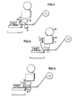
- Figure 1 is a schematic side elevational illustration of apparatus for use in the production of wire looms
- Figures 2 to 12 are schematic illustrations showing successive steps in the operation of the apparatus of Figure 1 to produce a wire loom.
- apparatus 1 for the production of wire looms is located generally above a conveyor 2 which conveys the completed looms away from the apparatus.
- the apparatus comprises a rectangular loom board 3 adapted to receive and hold guide pins to project upwardly from a flat upper surface of the board to define predetermined paths for the wires of the loom.
- a guide pin feeder 4 is disposed over the loom board 3 and is adapted to present the pins 4a (see Figures 2 to 14) to be gripped and removed by means of a mechanical gripper, such as one having a pair of relatively displaceable jaw members and a pneumatic actuator arranged to control the relative movement of the jaw members.
- the pins so supplied are double-ended to avoid the necessity for the feeder to distinguish between differently shaped pin ends and to select one such end for presentation to the gripper.
- the construction of the loom board is such as to permit the pins to be temporarily fixed at any point on the board and to be readily ejected when desired.
- the board is preferably pivotally mounted so as to be inverted, thereby to facilitate removal of wiring looms therefrom, and deposition of the looms upon the conveyor.
- a stop 5 and indexing unit 6 serve to locate the loom board properly with respect to the other components of the apparatus.
- the gripper 7 is part of an automatic manipulator, and is carried at the end of an articulated arm, indicated schematically, at 30 by a broken line.
- the movements of the arm and actuation of the gripper 7 are under electronic control from a central control unit 31 of the manipulator, the sequence of operational movements being predetermined and preprogrammed in a memory, or upon a suitable recording medium such as punched or magnetic tape, or floppy disc which bears coded commands for conversion into electrical signals which can be processed in the electronic control to actuate the gripper as required.
- An automatic manipulator which is particularly suitable for this purpose is the "Puma" robot made and sold by Unimation Inc., of Danbury, Connecticut, U.S.A.
- each wire 9 is supplied from a respective reel 10 and extends via one or more guide pulleys 11 through a wire drive assembly 12 comprising a drive capstan 13 and a pinch roller 14, and through a guide 15 to the respective cutter.
- Each unit 16 is capable of removing from an end of a wire properly presented thereto by the gripper, a predetermined length of insulation from the conductive core, and of placing over the bared wire an insulating sleeve.
- Units 17 are each capable of applying to the bared wire and, when properly presented thereto by the gripper, and after stripping and sleeve placement by a unit 16, an appropriate terminal element, such as a spade terminal.
- the unit 17 crimps the terminal onto bared wire end, and then moves the insulating sleeve over the crimped part of the terminal.
- the terminals may be supplied to the units 17 from a reel 19 in the form of a continuous strip 18 from which the individual terminals are cut.
- the first part of the sequence is the setting up of the required loom board to define the correct wire paths for the particular type of loom to be produced.
- the gripper operates under the pre-programmed electronic control to remove pins from the guide pin feeder 4, one at a time, and to place them on the board at predetermined positions, as illustrated in Figure 2, the board being adapted to receive and releasably hold the pins with a portion of each pin projecting from the board.
- the pins define the paths for the wires of the loom these paths consisting generally of a central trunk path along which a part of most, if not all of the wires, will extend, and a number of branch paths, projecting laterally from the trunk paths, along which the end portions of the wires will extend.
- the required wire reels 10 are then loaded on reel stands (not shown) in a manner and sequence as dictated by the programme controlling the electronic control, and the leading ends of the wire fed round the guide pulleys 11, through the wire drive assemblies 12 and guides 15.
- the gripper 7 then grips the wire projecting from a guide 15, leaving a projecting end portion 20, and the drive assembly 12 for that wire is actuated, as shown in Figure 3.
- a predetermined length of the wire is advanced by means of the drive capstan 13, and simultaneously the wire end portion 20 is presented to a stripper and sleeve dispenser unit 16, and then to a terminal supply and crimp unit 17, which operate upon the wire end as described hereinbefore.
- Figures 4 and 5 illustrate these two operations.
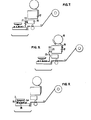
- the capstan 13 stops, and the gripper 7 then releases the now terminated wire end, and returns to take hold of the wire adjacent and just beyond the wire cutter 8, relative to the guide 15, as shown in Figure 6.
- the cutter 8 is then actuated by a signal from the electronic control, and the end portion 21 now held by the gripper is presented to the stripper and sleeve dispenser unit 16 and to the terminal supply and crimp unit 17, as illustrated in Figures 7 and 8.
- the gripper 7 then lays the cut and terminated length of wire 28 along its predetermined path by anchoring the end just terminated between a pair of pins at that end of the board and threading the wire between the pins 4a defining that path, as illustrated in Figure 9.
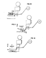
- an adhesive tape dispenser 25 operates to apply, at each of a number of specific points on the main trunk and branches of the loom, a length of tape drawn from a reel 26 to encircle and bind together the wire, as illustrated in Figure 10.
- the loom board 3 is then inverted, as shown in Figure 11 to drop the bound loom 27 onto the conveyor 2 which may convey the loom to a braiding machine (not shown) which applies a protective braiding to the entire loom.
- the board After ejecting any loom which is not to be the last of the batch, the board is reinverted so that the pins again project upwardly, and another similar loom of wires is assembled on the board, bound and ejected.
- the pins 4a After ejecting the last loom of the batch, the pins 4a are released from the board and jettisoned, as shown in Figure 12, while the board is still inverted and consequently fall onto the conveyor 2 whence they may be collected and returned to the guide pin feeder 4.
- the loom board after reinversion, is then ready to receive guide pins defining the wire paths of a different loom batch to be produced subsequently.
Priority Applications (1)
| Application Number | Priority Date | Filing Date | Title |
|---|---|---|---|
| AT79301087T ATE5923T1 (de) | 1978-06-15 | 1979-06-08 | Verfahren und apparat zum herstellen von drahtbuendeln. |
Applications Claiming Priority (2)
| Application Number | Priority Date | Filing Date | Title |
|---|---|---|---|
| GB7827015A GB2024052B (en) | 1978-06-15 | 1978-06-15 | Method and apparatus for wiring loom production |
| GB2701578 | 1978-06-15 |
Publications (3)
| Publication Number | Publication Date |
|---|---|
| EP0008155A1 true EP0008155A1 (fr) | 1980-02-20 |
| EP0008155B1 EP0008155B1 (fr) | 1984-01-18 |
| EP0008155B2 EP0008155B2 (fr) | 1991-10-16 |
Family
ID=10497981
Family Applications (1)
| Application Number | Title | Priority Date | Filing Date |
|---|---|---|---|
| EP79301087A Expired - Lifetime EP0008155B2 (fr) | 1978-06-15 | 1979-06-08 | Procédé et appareil pour la production de harnais de câblage |
Country Status (6)
| Country | Link |
|---|---|
| US (1) | US4348805A (fr) |
| EP (1) | EP0008155B2 (fr) |
| JP (2) | JPS5525993A (fr) |
| AT (1) | ATE5923T1 (fr) |
| DE (1) | DE2966546D1 (fr) |
| GB (1) | GB2024052B (fr) |
Cited By (10)
| Publication number | Priority date | Publication date | Assignee | Title |
|---|---|---|---|---|
| EP0039188A1 (fr) * | 1980-04-29 | 1981-11-04 | Lansing Bagnall Limited | Appareil applicateur à fonctionnement pneumatique et procédé pour appliquer une bande adhésive |
| EP0062413A2 (fr) * | 1981-03-25 | 1982-10-13 | British Aerospace Public Limited Company | Appareil et méthode pour la production de faisceaux de câblage |
| FR2547103A1 (fr) * | 1983-06-02 | 1984-12-07 | Sumitomo Electric Industries | Rubaneuse de harnais de cables |
| EP0137631A2 (fr) * | 1983-08-12 | 1985-04-17 | Sumitomo Electric Industries Limited | Appareil pour produire automatiquement un câble avec cosses serties |
| EP0182592A2 (fr) * | 1984-11-13 | 1986-05-28 | Westinghouse Electric Corporation | Système de fabrication automatique flexible |
| EP0182591A2 (fr) * | 1984-11-13 | 1986-05-28 | Unimation Inc. | Méthode et appareil pour la fabrication de faisceaux de fils à haute densité |
| WO1987005741A1 (fr) * | 1986-03-12 | 1987-09-24 | Komax Ag | Procede de production de cablages preassembles |
| EP0300141A1 (fr) * | 1987-07-20 | 1989-01-25 | Komax Ag | Dispositif pour une fabrication entièrement automatique de faisceaux de câbles |
| WO1989012900A1 (fr) * | 1988-06-18 | 1989-12-28 | Merz Metall- Und Kunststoffverarbeitungs Gmbh | Procede et dispositif de fabrication d'harnais de cables |
| CN112397967A (zh) * | 2020-09-29 | 2021-02-23 | 东莞理工学院 | 一种可对端子进行套管处理的自动端子铆压机 |
Families Citing this family (18)
| Publication number | Priority date | Publication date | Assignee | Title |
|---|---|---|---|---|
| US4976012A (en) * | 1982-11-29 | 1990-12-11 | E. I Du Pont De Nemours And Company | Method of forming a web |
| US4715924A (en) * | 1982-11-29 | 1987-12-29 | E. I. Du Pont De Nemours And Company | Apparatus for forming a web |
| GB8304103D0 (en) * | 1983-02-15 | 1983-03-16 | British Aerospace | Filament laying apparatus |
| US4622733A (en) * | 1984-01-25 | 1986-11-18 | Sumitomo Electric Industries, Ltd. | Branch wire connecting apparatus |
| US4683636A (en) * | 1984-11-13 | 1987-08-04 | Westinghouse Electric Corp. | Wire preparation system |
| US4653159A (en) * | 1984-11-13 | 1987-03-31 | Westinghouse Electric Corp. | Flexible automated manufacturing system |
| US4593452A (en) * | 1985-02-26 | 1986-06-10 | Amp Incorporated | Robotic harness maker |
| JPH0198389U (fr) * | 1987-12-22 | 1989-06-30 | ||
| JP2765354B2 (ja) * | 1992-03-09 | 1998-06-11 | 住友電装株式会社 | 接続具における電線の敷線方法 |
| ES2113801B1 (es) * | 1994-11-21 | 1999-01-01 | Mecanismos Aux Ind | Maquina de corte y desforrado en linea y su procedimiento de funcionamiento. |
| JP2942981B2 (ja) * | 1995-04-20 | 1999-08-30 | モレックス インコーポレーテッド | 電気コネクタハーネスの結束方法および装置 |
| JP2828026B2 (ja) * | 1996-04-25 | 1998-11-25 | 日本電気株式会社 | 自動配線方法 |
| US6519832B1 (en) * | 1998-07-27 | 2003-02-18 | Reliance Electric Technologies, Llc | Method for automated stator manufacture |
| EP1076385B1 (fr) * | 1999-08-10 | 2004-10-27 | Sumitomo Wiring Systems, Ltd. | Un procédé de connexion de fils et un dispositif de connexion de fils |
| US6412386B1 (en) * | 2001-03-14 | 2002-07-02 | Tony Tseng | Braided ribbon and its fabrication method |
| SI21332A (sl) * | 2002-10-30 | 2004-04-30 | Nikolaja Klob�i� | Naprava za izdelavo v vodilih nameščenih snopov električnih žic za ožičenja stavb in postopek izdelave in montaže le-teh |
| ITBO20040226A1 (it) * | 2004-04-20 | 2004-07-20 | Unimac Srl | Metodo e sistema per ottenere un fascio di fili contenente un determinato numeto di fili e,piu particolarmente, un fascio di fili ondulati |
| EP2466702A1 (fr) * | 2010-12-14 | 2012-06-20 | Tyco Electronics Nederland B.V. | Procédé et appareil de fabrication d'un assemblage de câble |
Citations (5)
| Publication number | Priority date | Publication date | Assignee | Title |
|---|---|---|---|---|
| US3186077A (en) * | 1963-07-09 | 1965-06-01 | Amp Inc | Apparatus for wiring panelboards |
| DE1299336B (de) * | 1964-01-14 | 1969-07-17 | Siemens Ag | Einrichtung zum automatischen Erstellen von Formkabeln fuer Fernmelde-, insbesondere Fernsprechanlagen |
| FR2069415A5 (fr) * | 1969-11-14 | 1971-09-03 | Amp Inc | |
| US3961703A (en) * | 1974-07-31 | 1976-06-08 | Lyall Electric, Inc. | Conveyor system for lengths of flexible material |
| US4024630A (en) * | 1973-04-26 | 1977-05-24 | L. M. Ericsson Pty. Ltd. | Machine for manufacturing cable forms |
Family Cites Families (7)
| Publication number | Priority date | Publication date | Assignee | Title |
|---|---|---|---|---|
| US3435858A (en) * | 1965-08-03 | 1969-04-01 | Int Standard Electric Corp | Wire wrapping machine |
| US3550236A (en) * | 1968-12-16 | 1970-12-29 | Wurlitzer Co | Piano stringing method |
| US3699630A (en) * | 1970-12-31 | 1972-10-24 | Hughes Aircraft Co | System for ordered dispensing of wire and the like |
| US3842496A (en) * | 1972-02-18 | 1974-10-22 | Boeing Co | Method and apparatus for semiautomatically manufacturing electrical wire harness |
| US4030527A (en) * | 1976-06-21 | 1977-06-21 | Xynetics, Inc. | Automatic cable forming system |
| JPS5342385A (en) * | 1976-09-30 | 1978-04-17 | Yazaki Corp | Process and apparatus for manufacturing wire harness |
| US4126935A (en) * | 1977-05-31 | 1978-11-28 | Bell Telephone Laboratories, Incorporated | Method and apparatus for manufacturing wiring harnesses |
-
1978
- 1978-06-15 GB GB7827015A patent/GB2024052B/en not_active Expired
-
1979
- 1979-06-08 AT AT79301087T patent/ATE5923T1/de not_active IP Right Cessation
- 1979-06-08 EP EP79301087A patent/EP0008155B2/fr not_active Expired - Lifetime
- 1979-06-08 DE DE7979301087T patent/DE2966546D1/de not_active Expired
- 1979-06-13 US US06/048,582 patent/US4348805A/en not_active Expired - Lifetime
- 1979-06-14 JP JP7513279A patent/JPS5525993A/ja active Pending
-
1986
- 1986-05-19 JP JP1986075207U patent/JPH0220737Y2/ja not_active Expired
Patent Citations (5)
| Publication number | Priority date | Publication date | Assignee | Title |
|---|---|---|---|---|
| US3186077A (en) * | 1963-07-09 | 1965-06-01 | Amp Inc | Apparatus for wiring panelboards |
| DE1299336B (de) * | 1964-01-14 | 1969-07-17 | Siemens Ag | Einrichtung zum automatischen Erstellen von Formkabeln fuer Fernmelde-, insbesondere Fernsprechanlagen |
| FR2069415A5 (fr) * | 1969-11-14 | 1971-09-03 | Amp Inc | |
| US4024630A (en) * | 1973-04-26 | 1977-05-24 | L. M. Ericsson Pty. Ltd. | Machine for manufacturing cable forms |
| US3961703A (en) * | 1974-07-31 | 1976-06-08 | Lyall Electric, Inc. | Conveyor system for lengths of flexible material |
Cited By (15)
| Publication number | Priority date | Publication date | Assignee | Title |
|---|---|---|---|---|
| EP0039188A1 (fr) * | 1980-04-29 | 1981-11-04 | Lansing Bagnall Limited | Appareil applicateur à fonctionnement pneumatique et procédé pour appliquer une bande adhésive |
| EP0062413A2 (fr) * | 1981-03-25 | 1982-10-13 | British Aerospace Public Limited Company | Appareil et méthode pour la production de faisceaux de câblage |
| EP0062413A3 (en) * | 1981-03-25 | 1983-03-30 | Lansing Bagnall Limited | Apparatus and method for the production of wiring looms |
| FR2547103A1 (fr) * | 1983-06-02 | 1984-12-07 | Sumitomo Electric Industries | Rubaneuse de harnais de cables |
| EP0137631A2 (fr) * | 1983-08-12 | 1985-04-17 | Sumitomo Electric Industries Limited | Appareil pour produire automatiquement un câble avec cosses serties |
| EP0137631A3 (en) * | 1983-08-12 | 1987-07-15 | Sumitomo Electric Industries Limited | Apparatus for automatically producing cable with crimped terminals |
| EP0182591A2 (fr) * | 1984-11-13 | 1986-05-28 | Unimation Inc. | Méthode et appareil pour la fabrication de faisceaux de fils à haute densité |
| EP0182592A2 (fr) * | 1984-11-13 | 1986-05-28 | Westinghouse Electric Corporation | Système de fabrication automatique flexible |
| EP0182591A3 (fr) * | 1984-11-13 | 1988-08-17 | Unimation Inc. | Méthode et appareil pour la fabrication de faisceaux de fils à haute densité |
| EP0182592A3 (fr) * | 1984-11-13 | 1988-08-31 | Westinghouse Electric Corporation | Système de fabrication automatique flexible |
| WO1987005741A1 (fr) * | 1986-03-12 | 1987-09-24 | Komax Ag | Procede de production de cablages preassembles |
| EP0300141A1 (fr) * | 1987-07-20 | 1989-01-25 | Komax Ag | Dispositif pour une fabrication entièrement automatique de faisceaux de câbles |
| WO1989012900A1 (fr) * | 1988-06-18 | 1989-12-28 | Merz Metall- Und Kunststoffverarbeitungs Gmbh | Procede et dispositif de fabrication d'harnais de cables |
| CN112397967A (zh) * | 2020-09-29 | 2021-02-23 | 东莞理工学院 | 一种可对端子进行套管处理的自动端子铆压机 |
| CN112397967B (zh) * | 2020-09-29 | 2022-03-01 | 佛山市顺德区恒沃电器有限公司 | 一种可对端子进行套管处理的自动端子铆压机 |
Also Published As
| Publication number | Publication date |
|---|---|
| JPS6226818U (fr) | 1987-02-18 |
| DE2966546D1 (en) | 1984-02-23 |
| EP0008155B2 (fr) | 1991-10-16 |
| JPH0220737Y2 (fr) | 1990-06-06 |
| GB2024052B (en) | 1982-07-14 |
| US4348805A (en) | 1982-09-14 |
| JPS5525993A (en) | 1980-02-25 |
| EP0008155B1 (fr) | 1984-01-18 |
| GB2024052A (en) | 1980-01-09 |
| ATE5923T1 (de) | 1984-02-15 |
Similar Documents
| Publication | Publication Date | Title |
|---|---|---|
| US4348805A (en) | Method for the production of wiring looms | |
| US11340575B2 (en) | Apparatus, system, and method for picking, placing, and melting solder sleeves onto shielded electrical wires and cables | |
| US4194281A (en) | Apparatus and method for stripping wire leads | |
| US4196510A (en) | Apparatus and method for production of wire leads | |
| EP0778587A3 (fr) | Fil électrique plat pour faisceau de fils et méthode et appareil de sa production | |
| JPS61277115A (ja) | 電気的ハーネスを製造する装置 | |
| EP2418658B1 (fr) | Dispositif de traitement de borne de fil électrique et procédé de traitement de borne de fil électrique | |
| US5214838A (en) | Method for inserting stator coil lead wires into terminals having wire-receiving channels | |
| US5090107A (en) | Apparatus for inserting stator coil lead wires into terminals having wire-receiving channels | |
| US4183383A (en) | Wire shaping mechanism for production of wire leads | |
| US5033188A (en) | Method of making an electrical harness | |
| US5224251A (en) | Electrical harness assembly apparatus | |
| JPS622478A (ja) | ケ−ブル導線端末部の被覆をむき取つて端子を圧着する装置及び方法 | |
| US4977934A (en) | Multiple wire straightener module for an automated cable assembly system | |
| JPH02214405A (ja) | 多芯電気ケーブル導線の剥離と終端処理の為の装置 | |
| EP0168141B1 (fr) | Appareil et méthode pour assembler des fils munis de terminaux pour fabriquer des faisceaux | |
| US4862927A (en) | Double-ended termination and routing arrangement for an automated wiring system | |
| EP0365137A1 (fr) | Procédé pour la fabrication de faisceau de câbles électriques | |
| US5067399A (en) | Wire marking apparatus for marking selected codes onto any of a plurality of wires | |
| EP0453311B2 (fr) | Méthode et appareil d'insertion des extrémités des fils de bobinage d'un stator dans des connecteurs ayant des cannaux de réception de conducteurs | |
| US4254547A (en) | Methods and apparatus for automatic jumper placement | |
| EP0412732A1 (fr) | Appareil pour l'assemblage de faisceaux de câbles électriques | |
| JPS61147412A (ja) | 枝付電線加工装置 | |
| JPH04501782A (ja) | ケーブルハーネスの製造方法と装置 | |
| JPH0574886B2 (fr) |
Legal Events
| Date | Code | Title | Description |
|---|---|---|---|
| PUAI | Public reference made under article 153(3) epc to a published international application that has entered the european phase |
Free format text: ORIGINAL CODE: 0009012 |
|
| AK | Designated contracting states |
Designated state(s): AT BE CH DE FR IT LU NL SE |
|
| 17P | Request for examination filed | ||
| ITF | It: translation for a ep patent filed |
Owner name: BARZANO' E ZANARDO MILANO S.P.A. |
|
| GRAA | (expected) grant |
Free format text: ORIGINAL CODE: 0009210 |
|
| AK | Designated contracting states |
Designated state(s): AT BE CH DE FR IT LU NL SE |
|
| REF | Corresponds to: |
Ref document number: 5923 Country of ref document: AT Date of ref document: 19840215 Kind code of ref document: T |
|
| REF | Corresponds to: |
Ref document number: 2966546 Country of ref document: DE Date of ref document: 19840223 |
|
| ET | Fr: translation filed | ||
| PG25 | Lapsed in a contracting state [announced via postgrant information from national office to epo] |
Ref country code: AT Effective date: 19840608 |
|
| PG25 | Lapsed in a contracting state [announced via postgrant information from national office to epo] |
Ref country code: LU Free format text: LAPSE BECAUSE OF NON-PAYMENT OF DUE FEES Effective date: 19840630 |
|
| PLBI | Opposition filed |
Free format text: ORIGINAL CODE: 0009260 |
|
| 26 | Opposition filed |
Opponent name: SIEMENS AKTIENGESELLSCHAFT, BERLIN UND MUENCHEN Effective date: 19841018 |
|
| BECH | Be: change of holder |
Free format text: 840118 *LANSING BAGNALL LTD;*BRITISH AEROSPACE PUBLIC LTD CY |
|
| PG25 | Lapsed in a contracting state [announced via postgrant information from national office to epo] |
Ref country code: NL Effective date: 19850101 |
|
| NLV4 | Nl: lapsed or anulled due to non-payment of the annual fee | ||
| BECN | Be: change of holder's name |
Effective date: 19851118 |
|
| REG | Reference to a national code |
Ref country code: CH Ref legal event code: PUE Owner name: BRITISH AEROSPACE PUBLIC LIMITED COMPANY |
|
| REG | Reference to a national code |
Ref country code: FR Ref legal event code: TP |
|
| RAP2 | Party data changed (patent owner data changed or rights of a patent transferred) |
Owner name: BRITISH AEROSPACE PUBLIC LIMITED COMPANY Owner name: LANSING BAGNALL LIMITED |
|
| ITF | It: translation for a ep patent filed |
Owner name: BARZANO' E ZANARDO ROMA S.P.A. |
|
| RAP2 | Party data changed (patent owner data changed or rights of a patent transferred) |
Owner name: BRITISH AEROSPACE PUBLIC LIMITED COMPANY |
|
| PGFP | Annual fee paid to national office [announced via postgrant information from national office to epo] |
Ref country code: CH Payment date: 19910613 Year of fee payment: 13 |
|
| PGFP | Annual fee paid to national office [announced via postgrant information from national office to epo] |
Ref country code: SE Payment date: 19910614 Year of fee payment: 13 |
|
| PGFP | Annual fee paid to national office [announced via postgrant information from national office to epo] |
Ref country code: FR Payment date: 19910621 Year of fee payment: 13 |
|
| ITTA | It: last paid annual fee | ||
| PUAH | Patent maintained in amended form |
Free format text: ORIGINAL CODE: 0009272 |
|
| STAA | Information on the status of an ep patent application or granted ep patent |
Free format text: STATUS: PATENT MAINTAINED AS AMENDED |
|
| PGFP | Annual fee paid to national office [announced via postgrant information from national office to epo] |
Ref country code: DE Payment date: 19910902 Year of fee payment: 13 |
|
| 27A | Patent maintained in amended form |
Effective date: 19911016 |
|
| AK | Designated contracting states |
Kind code of ref document: B2 Designated state(s): AT BE CH DE FR IT LU NL SE |
|
| REG | Reference to a national code |
Ref country code: CH Ref legal event code: AEN |
|
| EN3 | Fr: translation not filed ** decision concerning opposition | ||
| PG25 | Lapsed in a contracting state [announced via postgrant information from national office to epo] |
Ref country code: FR Effective date: 19920306 |
|
| PG25 | Lapsed in a contracting state [announced via postgrant information from national office to epo] |
Ref country code: SE Effective date: 19920609 |
|
| PG25 | Lapsed in a contracting state [announced via postgrant information from national office to epo] |
Ref country code: CH Effective date: 19920630 |
|
| PGFP | Annual fee paid to national office [announced via postgrant information from national office to epo] |
Ref country code: BE Payment date: 19920710 Year of fee payment: 14 |
|
| REG | Reference to a national code |
Ref country code: CH Ref legal event code: PL |
|
| PG25 | Lapsed in a contracting state [announced via postgrant information from national office to epo] |
Ref country code: DE Effective date: 19930302 |
|
| REG | Reference to a national code |
Ref country code: FR Ref legal event code: ST |
|
| PG25 | Lapsed in a contracting state [announced via postgrant information from national office to epo] |
Ref country code: BE Effective date: 19930630 |
|
| BERE | Be: lapsed |
Owner name: BRITISH AEROSPACE P.L.C. Effective date: 19930630 |
|
| EUG | Se: european patent has lapsed |
Ref document number: 79301087.7 Effective date: 19930109 |
|
| APAC | Appeal dossier modified |
Free format text: ORIGINAL CODE: EPIDOS NOAPO |
|
| APAC | Appeal dossier modified |
Free format text: ORIGINAL CODE: EPIDOS NOAPO |
|
| APAH | Appeal reference modified |
Free format text: ORIGINAL CODE: EPIDOSCREFNO |