EP0001189A2 - Dispositif pour la correction du tirage dans les tours de refroidissement notamment à tirage naturel - Google Patents
Dispositif pour la correction du tirage dans les tours de refroidissement notamment à tirage naturel Download PDFInfo
- Publication number
- EP0001189A2 EP0001189A2 EP78400054A EP78400054A EP0001189A2 EP 0001189 A2 EP0001189 A2 EP 0001189A2 EP 78400054 A EP78400054 A EP 78400054A EP 78400054 A EP78400054 A EP 78400054A EP 0001189 A2 EP0001189 A2 EP 0001189A2
- Authority
- EP
- European Patent Office
- Prior art keywords
- tower
- exchangers
- base
- screens
- posts
- Prior art date
- Legal status (The legal status is an assumption and is not a legal conclusion. Google has not performed a legal analysis and makes no representation as to the accuracy of the status listed.)
- Granted
Links
Images

Classifications
-
- F—MECHANICAL ENGINEERING; LIGHTING; HEATING; WEAPONS; BLASTING
- F28—HEAT EXCHANGE IN GENERAL
- F28B—STEAM OR VAPOUR CONDENSERS
- F28B1/00—Condensers in which the steam or vapour is separate from the cooling medium by walls, e.g. surface condenser
- F28B1/06—Condensers in which the steam or vapour is separate from the cooling medium by walls, e.g. surface condenser using air or other gas as the cooling medium
Definitions
- the present invention due to the collaboration of Mr. Jean MAURICE, relates to a method and to a device for the correction of the draft in cooling towers in particular with natural draft.
- Such air coolers are mainly used for the dissipation of excess calories not transformed into electricity, in power plants of all kinds, especially thermal and nuclear.
- a cooling tower for example of the so-called dry type, is essentially constituted by a shell of revolution forming a chimney, of great height, supported at its base by a crown of posts (obliques) surmounted by a circular lintel.
- the heat exchangers in which circulate in closed circuits the fluid or fluids to be cooled, can be produced in batteries or by simple pipes or fitted with fins.
- the exchanger batteries are arranged on a cross section of the hull in the vicinity of the base, that is to say in a general horizontal plane at a certain height relative to the ground.
- the exchangers rest on a metallic lattice structure, supported by vertical posts installed on the base surface of the tower.
- the cold air or outside wind arrives through the base of the tower, between the various support posts, and passes vertically through the exchangers to exit towards the top of the tower by dissipating the calories into the atmosphere.
- the tower is calculated and structured to ensure the dissipation of the noninal thermal flux, as is notably the case for the process and the tower developed by the present applicant in another French demsrde.
- the method according to the invention consists in breaking the dynamic pressure of the wind at the base of the tower to recreate a calm environment and in directing it towards the exchangers by a series of suitable means in order to ensure the dissipation of the nominal thermal flux.
- the invention presents several devices essentially characterized by the installation of a series of various deflector screens, fixed or mobile, of guide vanes and of orientation correction flaps, used separately or in combination.
- FIG. 1a one recognizes the base of a cooling tower roughly comprising a shell 1 supported at its base by a crown of oblique posts 2 surmounted by a circular lintel 3.
- the exchangers 4 installed on a general horizontal plane some distance from the ground 5, are supported by a series of vertical posts 6 visible in FIG. 6b.
- the wind arriving horizontally along the arrow F 1 is broken and deflected through the exchangers (F 2 ), by means of a plurality of radial screens 7 arranged vertically at the base of the tower, concurrent on the axis of symmetry 8 and inscribed in a surface corresponding substantially to the projection 9 on the ground of the heat exchange surface.
- Each branch of the star thus formed can take various forms, in particular rectangular (fig. 1a), triangular (dotted lines 17, fig. 1a), preferably trapezoidal, truncated either vertically (fig. 2), either horizontally (fig. 3), or again according to a combination of the preceding forms, with a variable height which can reach the lower face 10 of the heat exchanger bank.
- the star represented is with eight branches, but it goes without saying that the number of branches can be any, preferably from four to twelve, symmetrical or not.
- deflector screens can, in any case, be solid or perforated according to variable wind permeability. This is how they can be made of concrete, sheet metal or using tensile structures. A deployable net with large meshes notably facilitates access to the exchangers, for maintenance for example.
- the corrective device according to the invention makes it possible to reduce the increase in pressure drop due to wind, compared to windless operation, in the approximate proportion of 4.7 to 2.
- the solution of figure 4 represents a contiru circular screen 11 installed at the outer periphery of the tower, of sufficient height to break the wind, in relation to the distance D from the base of the tower.
- This screen 11 can be produced economically by one or more rows of trees or by a metal or concrete wall, by way of non-limiting examples.
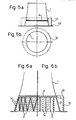
- FIGS. 5a and 5b illustrate a screen 12 in the form of a sector, more or less permeable to winds depending on the material used, mobile on rail 13 and arranged according to the orientation of the incident wind. It can consist of one or more motorized elements, preferably at the immediate periphery of the tower and of sufficient height.
- FIGS. 6a and 6b illustrate various variants adopting fixed guide vanes 14 for orienting and channeling the wind towards the exchangers 4.
- These vanes can be distributed either between the oblique posts 2 supporting the shell 1 of the tower (FIG. 6a), either between the vertical posts 6 supporting the exchangers according to an inner ring (fig. 6b ⁇ or again according to an outer ring 15 at the base of the tower, knowing that the latter case requires a box 16 for connection to the lintel 3 of the hull ( Fig. 6b)
- Various combinations of the previous variants are allowed.
- the invention is not limited to the exemplary embodiments described, but also encompasses all the technical equivalents meeting the desired goal.
Landscapes
- Engineering & Computer Science (AREA)
- Mechanical Engineering (AREA)
- General Engineering & Computer Science (AREA)
- Heat-Exchange Devices With Radiators And Conduit Assemblies (AREA)
- Separation By Low-Temperature Treatments (AREA)
Abstract
Description
- La présente invention, due à la collaboration de M. Jean MAURICE, se rapporte à un procédé et à un dispositif pour la correction du tirage dans les tours de refroidissement notamment à tirage naturel.
- De tels aéroréfrigérants sont principalement utilisés pour la dissipation du surplus de calories non transformées en électricité, dans les centrales de toutes sortes, notamment thermiques et nucléaires.
- Une tour de refroidissement, par exemple du type dite sèche, est essentiellement constituée par une coque de révolution formant cheminée, de grande hauteur, supportée à sa base par une couronne de poteaux (obliques) surmontés d'un linteau circulaire. Les échangeurs de chaleur, dans lesquels circulent en circuits fermés le ou les fluides à refroidir, peuvent être réalisés en batteries ou par des tuyaux simples ou munis d'ailettes.
- Dans le cas qui intéresse le demandeur, les batteries d'échangeurs sont disposées sur une section droite de la coque au voisinage de la base, c'est-à-dire dans un plan général horizontal à une certaine hauteur par rapport au sol.
- Les échangeurs reposent sur une charpente métallique en treillis, soutenue par des poteaux verticaux implantés sur la surface de base de la tour.
- Avec cette disposition, l'air froid ou vent extérieur arrive par la base de la tour, entre les différents poteaux supports, et traverse verticalement les échangeurs pour ressortir vers le sommet de la tour en dissipant les calories à l'atmosphère.
- La tour est calculée et structurée pour assurer la dissipation du flux thermique noninal, comme c'est notamment le cas pour le procédé et la tour mis au point par le présent demandeur dans une autre demsrde française.
- Par vents forts et très forts, ces derniers traversent la base de la tour horizontalement à une vitesse telle que le débit d'air vertical à travers la batterie d'échangeurs devient insuffisant. Ce phénomène correspond à une augmentation virtuelle rapide de l'ensemble des pertes de charge de la tour, qu'il s'agit de réduire le plus possible pour rétablir le débit d'air nominal et assurer la dissipation du flux thermique nominal. C'est le but poursuivi par la présente invention.
- Pour augmenter la force ascensionnelle nécessaire à l'extraction de l'air chaud, une solution consisterait à augmenter notablement la hauteur de la tour, ce qui ne peut être retenu valablement pour des raisons économiques.
- Le procédé selon l'invention consiste à briser la pression dynamique du vent à la base de la tour pour recréer un environnement calme et à l'orienter vers les échangeurs par une série de moyens approprias afin d'assurer la dissipation du flux thermique nominal.
- Pour la mise en oeuvre du procédé, l'invention présente plusieurs dispositifs caractérisés essentiellement par l'installation d'une série d'écrans déflecteurs divers,fixes ou mobiles, d'aubages directeurs et de volets de correction d'orientation, utilisés séparément ou en combinaison.
- D'autres caractéristiques apparaîtront au cours de la description qui suit de plusieurs variantes de réalisation de l'invention, en référence au dessin annexé sur lequel :
- - les figures la et 1b représentent schématiquement, respectivement en élévation et demi-vue de dessus, la base d'une tour équipée d'écrans déflecteurs de forme rectangulaire ou triangulaire répartis en étoile,
- - les figures 2 et 3 représentent des écrans déflecteurs à profil trapé- zoidal, respectivement tronqués verticalement et horizuntalement,
- - la figure 4 représente un écran circulaire continu à l'extérieur du périmètre de la tour,
- - les figures 5a et 5b représentert, en élévation et vuede dessus, un écran en forme de secteur mobile, et
- - les figures 6a et 6b représentent, en élévation et en demi-coupes,des aubages directeurs ou des volets réglables installés respectivement soit entre les poteaux obliques supports de la coque,soit entre les poteaux verticaux soutenant les échangeurs ou selon une couronne de poteaux extérieure à la tour.
- Sur la figure 1a, on reconnait la base d'une tour de refroidissement comprenant grossièrement une coque 1 supportée à sa base par une couronne de poteaux obliques 2 surmontes d'un linteau circulaire 3.
- Les échangeurs 4, installés sur un plan général horizontal à quelque distance du sol 5, sont supportés par une série de poteaux verticaux 6 visibles sur le figure 6b.
- Conformément à une première série de variantes de réalisation de l'invention, le vent arrivant horizontalement selon la flèche F1 est brisé et dévié à travers les échangeurs (F2), au moyen d'une pluralité d'écrans radiaux 7 disposés verticalement à la base de la tour, concourants sur l'axe de symétrie 8 et inscrits dans une surface correspondant sensiblement à la projection 9 sur le sol de la surface d'échange thermique.
- Chaque branche de l'étoile ainsi formée (fig. 1b) peut revêtir des formes diverses, notamment rectangulaires (fig. 1a), triangulaires (pointillés 17, fig. 1a), de préférence trapézoidales, tronquées soit verticalement (fig. 2), soit horizontalement (fig. 3), soit encore selon une combinaison des formes précédentes, avec une hauteur variable pouvant atteindre la face inférieure 10 de la batterie d'échangeurs.
- L'étoile représentée est à huit branches, mais il va de soi que le nombre de branches peut être quelconque, de préférence de quatre à douze, symétriques ou non.
- Ces écrans déflecteurs peuvent, dans tous les cas, être pleins ou ajourés selon une perméabilité aux vents variable. C'est ainsi que l'on peut les réaliser en béton, en tôle ou à l'aide de structures tendues. Un filet déployable à grosses mailles permet notamment de faciliter l'accès aux échangeurs, pour la maintenance par exemple.
- Les résultats satisfaisants obtenus par cette disposition des écrans peuvent être illustrés par l'exemple numérique suivant, valable en particulier pour des écrans triangulaires ou trapézoïdaux : pour un fonctionnement pa- vent assez fort, soit un rapport de 4,5 entre la vitesse du vent en bas de la tour (horizontal, de l'ordre de 75 km/heure) et celle de l'air à la sortie de la tour (vertical), le dispositif correcteur selon invention permet de réduire l'augmentation de la perte de charge due au vent, par rapport à un fonctionnement sans vent, dans la proportion approx mative de 4,7 à 2.
- Des résultats analogues peuvent être obtenus par d'autres solutions en variantes.
- La solution de la figure 4 représente un écran circulaire contiru 11 installé a la périphérie extérieure de la tour, de hauteur suffisante pour briser le vent, en rapport avec l'éloignement D de la base de la tour.
- Cet écran 11 peut être réalisé économiquement par une ou plusieurs rangées d'arbres ou par un mur métallique ou en béton, à titre d'exemples non limitatifs.
- Les figures 5a et 5b illustrent un écran 12 en forme de secteur, plus ou moins perméable aux vents selon le matériau utilisé, mobile sur rail 13 et disposé selon l'orientation du vent incident. Il peut être constitué d'un ou plusieurs éléments motorisés, de préférence à la périphérie immédiate de la tour et de hauteur suffisante.
- Les figures 6a et 6b illustrent diverses variantes adoptant des aubages directeurs 14 fixes pour orienter et canaliser le vent en direction des échangeurs 4. Ces aubages peuvent être répartis soit entre les poteaux obliques 2 supportant la coque 1 de la tour (fig. 6a),soit entre les poteaux verticaux 6 soutenant les échangeurs selon une couronne intérieure (fig. 6b\ soit encore selon une couronne extérieure 15 à la base de la tour, sachant que ce dernier cas nécessite un caisson 16 de raccordement au linteau 3 de la coque (fig. 6b). Diverses combinaisons des variantes précédentes sont permises.
- En reprenant les dispositions des figures 6a et 6b, il est encore possible de remplacer les aubages directeurs 14 par des volets mobiles de correction de l'orientation du vent, actionnés manuellement ou automatiquement.
- L'invention n'est pas limitée aux exemples de réalisation décrits, mais englobe également tous les équivalents techniques répondant au but recherché.
Claims (11)
Applications Claiming Priority (2)
| Application Number | Priority Date | Filing Date | Title |
|---|---|---|---|
| FR7722598 | 1977-07-22 | ||
| FR7722598A FR2398277A1 (fr) | 1977-07-22 | 1977-07-22 | Procede et dispositif pour la correction du tirage dans les tours de refroidissement notamment a tirage naturel |
Publications (3)
| Publication Number | Publication Date |
|---|---|
| EP0001189A2 true EP0001189A2 (fr) | 1979-03-21 |
| EP0001189A3 EP0001189A3 (en) | 1979-04-04 |
| EP0001189B1 EP0001189B1 (fr) | 1981-05-20 |
Family
ID=9193694
Family Applications (1)
| Application Number | Title | Priority Date | Filing Date |
|---|---|---|---|
| EP78400054A Expired EP0001189B1 (fr) | 1977-07-22 | 1978-07-05 | Dispositif pour la correction du tirage dans les tours de refroidissement notamment à tirage naturel |
Country Status (5)
| Country | Link |
|---|---|
| EP (1) | EP0001189B1 (fr) |
| BR (1) | BR7804729A (fr) |
| DE (1) | DE2860712D1 (fr) |
| FR (1) | FR2398277A1 (fr) |
| IT (1) | IT1108780B (fr) |
Families Citing this family (2)
| Publication number | Priority date | Publication date | Assignee | Title |
|---|---|---|---|---|
| FR3057652B1 (fr) * | 2016-10-17 | 2019-09-13 | Hamon Thermal Europe (France) | Dispositif de controle de flux d'air, destine a equiper une tour de refroidissement, notamment de centrale thermique |
| CN112611250B (zh) * | 2021-01-13 | 2022-07-29 | 暨南大学 | 一种主动式流场重构空冷塔 |
Citations (12)
| Publication number | Priority date | Publication date | Assignee | Title |
|---|---|---|---|---|
| GB282932A (en) * | 1926-10-21 | 1928-01-05 | Karl Wladimir Branczik | Improvements in or relating to cooling towers |
| DE548291C (de) * | 1932-04-11 | Fritz Uhde | Kaminkuehler, dessen Rieseleinbau ueber den Kaminquerschnitt hinausreicht | |
| GB577308A (en) * | 1944-11-06 | 1946-05-13 | Frederick Gilbert Mitchell | Improvements in or relating to cooling towers |
| GB616032A (en) * | 1946-08-21 | 1949-01-14 | Northmet Power Company | Improvements in or relating to cooling towers and their operation |
| FR1072106A (fr) * | 1953-02-23 | 1954-09-08 | Radiateurs cylindriques | |
| FR1235872A (fr) * | 1958-09-25 | 1960-07-08 | Gea Luftkuehler Happel Gmbh | Perfectionnements apportés aux installations de condensation refroidies par de l'air |
| GB1045595A (en) * | 1964-03-17 | 1966-10-12 | English Electric Co Ltd | Dry cooling towers |
| DE1235343B (de) * | 1957-07-17 | 1967-03-02 | Kraftanlagen Ag | Rieselkuehler mit Luftleitflaechen |
| US3367413A (en) * | 1965-01-26 | 1968-02-06 | English Electric Co Ltd | Cooling towers |
| DE1960619A1 (de) * | 1969-12-03 | 1971-06-24 | Gea Luftkuehler Happel Gmbh | Kuehlturm fuer dampffoermige oder fluessige Medien |
| DE2153967A1 (de) * | 1971-10-29 | 1973-05-10 | Kraftwerk Union Ag | Naturzug-kuehlturm |
| FR2198113A1 (fr) * | 1972-08-29 | 1974-03-29 | Transelektro Magyar Villamossa |
-
1977
- 1977-07-22 FR FR7722598A patent/FR2398277A1/fr active Granted
-
1978
- 1978-07-05 DE DE7878400054T patent/DE2860712D1/de not_active Expired
- 1978-07-05 EP EP78400054A patent/EP0001189B1/fr not_active Expired
- 1978-07-21 BR BR7804729A patent/BR7804729A/pt unknown
- 1978-07-21 IT IT68745/78A patent/IT1108780B/it active
Patent Citations (12)
| Publication number | Priority date | Publication date | Assignee | Title |
|---|---|---|---|---|
| DE548291C (de) * | 1932-04-11 | Fritz Uhde | Kaminkuehler, dessen Rieseleinbau ueber den Kaminquerschnitt hinausreicht | |
| GB282932A (en) * | 1926-10-21 | 1928-01-05 | Karl Wladimir Branczik | Improvements in or relating to cooling towers |
| GB577308A (en) * | 1944-11-06 | 1946-05-13 | Frederick Gilbert Mitchell | Improvements in or relating to cooling towers |
| GB616032A (en) * | 1946-08-21 | 1949-01-14 | Northmet Power Company | Improvements in or relating to cooling towers and their operation |
| FR1072106A (fr) * | 1953-02-23 | 1954-09-08 | Radiateurs cylindriques | |
| DE1235343B (de) * | 1957-07-17 | 1967-03-02 | Kraftanlagen Ag | Rieselkuehler mit Luftleitflaechen |
| FR1235872A (fr) * | 1958-09-25 | 1960-07-08 | Gea Luftkuehler Happel Gmbh | Perfectionnements apportés aux installations de condensation refroidies par de l'air |
| GB1045595A (en) * | 1964-03-17 | 1966-10-12 | English Electric Co Ltd | Dry cooling towers |
| US3367413A (en) * | 1965-01-26 | 1968-02-06 | English Electric Co Ltd | Cooling towers |
| DE1960619A1 (de) * | 1969-12-03 | 1971-06-24 | Gea Luftkuehler Happel Gmbh | Kuehlturm fuer dampffoermige oder fluessige Medien |
| DE2153967A1 (de) * | 1971-10-29 | 1973-05-10 | Kraftwerk Union Ag | Naturzug-kuehlturm |
| FR2198113A1 (fr) * | 1972-08-29 | 1974-03-29 | Transelektro Magyar Villamossa |
Also Published As
| Publication number | Publication date |
|---|---|
| DE2860712D1 (en) | 1981-08-27 |
| EP0001189B1 (fr) | 1981-05-20 |
| FR2398277A1 (fr) | 1979-02-16 |
| IT7868745A0 (it) | 1978-07-21 |
| FR2398277B1 (fr) | 1981-03-20 |
| BR7804729A (pt) | 1979-02-28 |
| EP0001189A3 (en) | 1979-04-04 |
| IT1108780B (it) | 1985-12-09 |
Similar Documents
| Publication | Publication Date | Title |
|---|---|---|
| CA2602466C (fr) | Eolienne a axe vertical comprenant des dispositifs de guidage | |
| US4474529A (en) | Windmill | |
| JP5738203B2 (ja) | オフショア風力発電パーク | |
| US7918650B2 (en) | System for pressurizing fluid | |
| US8207625B1 (en) | Electrical power generating arrangement | |
| US20100199668A1 (en) | Air power generator tower | |
| EP1741927A1 (fr) | Générateur d'énergie à cheminée solaire | |
| US6755608B2 (en) | Wind turbine enhancement apparatus, method and system | |
| US3895882A (en) | Windmill structure | |
| EA014198B1 (ru) | Ветроэнергоустановка (варианты) | |
| KR101215402B1 (ko) | 수상 태양광 발전장치 | |
| EP0001189A2 (fr) | Dispositif pour la correction du tirage dans les tours de refroidissement notamment à tirage naturel | |
| US5744871A (en) | Wind system for electric power generation | |
| US4020899A (en) | Atmospheric cooling tower with dry-type heat exchangers | |
| US9897076B1 (en) | Solar power tower with spray nozzle and rotating receiver | |
| FR2504666A1 (fr) | Tour de refroidissement notamment pour centrale electrique | |
| CA2754000C (fr) | Eolienne | |
| CA1174546A (fr) | Roue solaire | |
| DE19806489A1 (de) | Thermosolares Aufwindkraftwerk | |
| US4267883A (en) | Cooling tower | |
| JP5065535B1 (ja) | 太陽光風力発電装置 | |
| US9970416B2 (en) | Energy conversion device driven by wind power | |
| GB2031139A (en) | Process and apparatus for correcting the draught in natural draught dry-process cooling towers | |
| CN100366894C (zh) | 风力回收装置 | |
| US10495065B2 (en) | Multi-turbine platform tower assembly and related methods systems, and apparatus |
Legal Events
| Date | Code | Title | Description |
|---|---|---|---|
| PUAI | Public reference made under article 153(3) epc to a published international application that has entered the european phase |
Free format text: ORIGINAL CODE: 0009012 |
|
| PUAL | Search report despatched |
Free format text: ORIGINAL CODE: 0009013 |
|
| AK | Designated contracting states |
Designated state(s): DE GB SE |
|
| AK | Designated contracting states |
Designated state(s): DE GB SE |
|
| 17P | Request for examination filed | ||
| GRAA | (expected) grant |
Free format text: ORIGINAL CODE: 0009210 |
|
| AK | Designated contracting states |
Designated state(s): DE GB SE |
|
| REF | Corresponds to: |
Ref document number: 2860712 Country of ref document: DE Date of ref document: 19810827 |
|
| PLBI | Opposition filed |
Free format text: ORIGINAL CODE: 0009260 |
|
| 26 | Opposition filed |
Opponent name: HAMON-SOBELCO S.A. Effective date: 19820212 |
|
| PLAB | Opposition data, opponent's data or that of the opponent's representative modified |
Free format text: ORIGINAL CODE: 0009299OPPO |
|
| R26 | Opposition filed (corrected) |
Opponent name: HAMON-SOBELCO S.A. Effective date: 19820212 |
|
| PGFP | Annual fee paid to national office [announced via postgrant information from national office to epo] |
Ref country code: DE Payment date: 19840618 Year of fee payment: 7 |
|
| PGFP | Annual fee paid to national office [announced via postgrant information from national office to epo] |
Ref country code: SE Payment date: 19840630 Year of fee payment: 7 |
|
| RDAG | Patent revoked |
Free format text: ORIGINAL CODE: 0009271 |
|
| STAA | Information on the status of an ep patent application or granted ep patent |
Free format text: STATUS: PATENT REVOKED |
|
| GBPR | Gb: patent revoked under art. 102 of the ep convention designating the uk as contracting state | ||
| 27W | Patent revoked |
Effective date: 19841222 |
|
| EUG | Se: european patent has lapsed |
Ref document number: 78400054.9 Effective date: 19860729 |