EP0000181A1 - Procédé et dispositif de solidification de substances toxiques et résiduelles, notamment de substances radioactives. - Google Patents
Procédé et dispositif de solidification de substances toxiques et résiduelles, notamment de substances radioactives. Download PDFInfo
- Publication number
- EP0000181A1 EP0000181A1 EP78100216A EP78100216A EP0000181A1 EP 0000181 A1 EP0000181 A1 EP 0000181A1 EP 78100216 A EP78100216 A EP 78100216A EP 78100216 A EP78100216 A EP 78100216A EP 0000181 A1 EP0000181 A1 EP 0000181A1
- Authority
- EP
- European Patent Office
- Prior art keywords
- filter
- container
- waste materials
- filter medium
- waste
- Prior art date
- Legal status (The legal status is an assumption and is not a legal conclusion. Google has not performed a legal analysis and makes no representation as to the accuracy of the status listed.)
- Withdrawn
Links
Images
Classifications
-
- G—PHYSICS
- G21—NUCLEAR PHYSICS; NUCLEAR ENGINEERING
- G21F—PROTECTION AGAINST X-RADIATION, GAMMA RADIATION, CORPUSCULAR RADIATION OR PARTICLE BOMBARDMENT; TREATING RADIOACTIVELY CONTAMINATED MATERIAL; DECONTAMINATION ARRANGEMENTS THEREFOR
- G21F9/00—Treating radioactively contaminated material; Decontamination arrangements therefor
- G21F9/04—Treating liquids
- G21F9/06—Processing
- G21F9/08—Processing by evaporation; by distillation
Definitions
- the invention relates to a method and a device for solidifying, in particular, radioactive pollutants or waste materials to form storable masses or solids, in which the waste materials accumulating as suspensions or solutions are incorporated into neutral substances which bind them and, if necessary, harden with them.
- Radioactive waste from nuclear power plants or the like is produced in the form of aqueous sludges which must be removed in such a way that they cannot cause any environmental damage over a long period of time.
- aqueous sludges which must be removed in such a way that they cannot cause any environmental damage over a long period of time.
- the solidified and hardened masses are then stored in sealed containers in underground rooms, for example in abandoned ones Salt mines stored from where the radioactive radiation from the waste materials can no longer reach the surface of the earth and cause damage there.
- the known methods for solidifying radioactive waste have the disadvantage that relatively large amounts of concrete mix are required to bind the radioactive waste sludge and that with the solidification of the radioactive sludge an increase in volume occurs at twice the amount of sludge.
- the solidified and hardened concrete bodies, which contain the radioactive substances, also have a significant weight and their final storage requires high expenditure.
- the object of the invention is to avoid these disadvantages and to provide a method and a device with which it is possible to avoid an increase in volume when solidifying in particular radioactive waste and to enclose the resulting pollutants or waste materials with the smallest possible amounts of neutral substances and to render it harmless.
- the waste material solution or suspension is passed through a precoat filter which, after it has been loaded with the waste materials, is depressurized by pressure reduction and is thereby frozen (freeze drying), the solution or suspensions being liquid speed escapes as vapor and is precipitated, and that afterwards the solid filter, which is loaded with the pollutants on its surface, a solidifying agent, in particular a hydrocarbon, a plastic, cement milk, silicates, in particular alkali silicates, or a mixture of these substances, which is fed into the Cavities of the filter penetrates and completely surrounds it.
- a solidifying agent in particular a hydrocarbon, a plastic, cement milk, silicates, in particular alkali silicates, or a mixture of these substances, which is fed into the Cavities of the filter penetrates and completely surrounds it.
- the filter In order to allow the evaporation to proceed as quickly as possible, the filter, after freezing the suspension adhering to it, is expediently supplied with the necessary evaporation heat by microwaves in such an amount that the frozen suspension liquid changes from the solid state of matter directly to the gaseous state.
- microwaves This has the effect that, on the one hand, the evaporation process is promoted and, on the other hand, thawing of the ice crystals of the pollutant suspension adhering to the filter is prevented.
- the microwaves heat the entire filter very evenly, so that there is no need to fear local thawing of the frozen pollutant suspension.
- the vapor escaping from the filter when the precipitate is deposited can also be used nene heat can be fed back to the precoat filter as heat of vaporization.
- the solidifying agents supplied to the dried filter have such a molecular structure that they cannot penetrate and fill all cavities of the filter, it is expedient to comminute the filter loaded with the waste materials after it has dried and then to mix them with the supplied solidifying agents. This ensures that the entire filter medium is coated with the solidifying agents.
- Silica gel (diatomaceous earth) is expediently used as the filter medium for the precoat filters.
- filter materials that are suitable for storing the waste materials to be bound are also possible.
- thermoplastic polymer resins and their precursors for example styrene
- thermosetting synthetic resins and the styrene can be hardened by chemical additives.
- nan uses a device which is characterized by a closed container which is at least partially filled with a filter medium and which has an inlet line for the suspension loaded with the waste materials, a return line for the waste materials after passing through the filter freed suspension liquid and an evaporation line.
- the device also consists of a vacuum pump connected to the evaporation line, a heat supply device connected to the container, a cooling unit for cooling the filter medium arranged inside the container and a device for supplying solidifying agents.
- the cooling unit is expediently connected on the one hand to the container with the filter medium and on the other hand to a steam condenser which is arranged in a vacuum receiver between the container and the vacuum pump Filter medium are supplied again in order to provide the heat of vaporization required to dry the filter medium or to evaporate the suspension liquid frozen into ice.
- a residual moisture separator can be connected upstream of the vacuum pump and a molecular filter can be connected downstream.
- the upstream separator has the task of separating the residual moisture from the vapors drawn off from the container, which is not condensed out in the vacuum storage container. Any entrained particles are separated in the downstream molecular filter.
- the air emerging from the molecular filter is expediently fed to the exhaust air of the nuclear reactor, where it is filtered again through an absolute filter.
- the drain lines of the vacuum receiver, the separator and the molecular filter are expediently connected to the return line, which feeds the filtered suspension liquid leaving the container to the reactor for reuse.
- a stirrer for comminuting the filter medium can be arranged in the container, the stirrer shaft protruding from the container being driven by a motor.
- the device for supplying the solidifying agent can expediently be connected to the container via the return line. After the loaded filter has completely dried, this return line is out of operation, so that the solidifying agent can be supplied to the filter medium through the return line from below, which in turn displaces air or gas from all cavities of the filter upwards, the gas or Air can escape through the evaporation line, while the rising solidifying agent completely fills the cavities contained in the filter.
- the cooling unit arranged between the container and the vacuum receiver is expediently reversible. This makes it possible, when the condenser is iced up, to supply heat to the condenser from the container via the cooling unit, thereby defrosting the condenser. At the same time, cold is supplied to the container in order to support the freeze-drying process in the container.
- the heat supply device for supplying microwaves to the filter medium is expediently a burl aggregate of a type known per se.
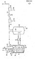
- 10 denotes a container for the final storage of radioactive waste materials, in which a filter 11 is arranged, which largely fills the interior 12 of the container.
- the filter medium 11a is kieselguhr (silica gel), which is supported on a perforated intermediate floor 12 'through which the liquid to be filtered can pass and collect in the deepest part 13 of the container 10.
- the container is tightly closed by at least one lid 14, which connecting piece for one Inlet line 13 for the suspension loaded with the waste materials, a return line 16 for the suspension liquid freed from the waste materials after passing through the filter 11 and an evaporation line 17.
- a pipe 19 extends from the connecting piece 17 of the return line into the lowermost part 13 of the container, in which the suspension liquid freed of the waste materials is located.
- a device 20 for supplying a solidifying agent can be connected to the return line 16, which is indicated in the drawing by the double arrow 21.
- an agitator 22 is arranged, which is attached to the agitator shaft 23, which protrudes through the lid 14 of the container at the top and is driven by a motor 24.
- a burl which is only indicated schematically in the drawing and is designated by 25 and which can evenly apply microwaves to the filter medium 11a arranged in the interior of the container.
- the vacuum line 17 first leads to a vacuum receiver 26 and from there through a separator 27 to a vacuum pump 28, which uses the pressure in the container 10.
- the exhaust air blown off by the vacuum pump is fed through the exhaust air line 29 and a molecular filter 30 to the exhaust air of the nuclear reactor, which radioactive waste materials are intended to solidify the notion shown.
- the vacuum receiver 26 there is a steam condenser 30, which is connected to a cooling unit 31, which on the other hand acts on the container 10 and supplies the heat extracted from the condenser 30 to the container 10 and the filter arranged in it.
- the cooling unit 31 is reversible, i.e. ea can also be operated in such a way that it extracts heat from the filter 11 and feeds it back to the condenser 30 when it is iced up and must be defrosted.
- the vacuum receiver 26, the separator 28 and the molecular filter 30 have drain lines 32, 33 and 34, respectively, which can be connected to the return line 16 and which feed the separated water together with the filtered suspension liquid back to the nuclear reactor.
- the filter medium 11a is so highly loaded with radioactive waste that the filter has to be replaced. For this purpose, however, it is not removed from the container 10, but the container 10 is exchanged for an identical container with a fresh filter 11. Before that, however, the filter medium 11 is solidified with the waste materials adhering to it. This is done in the following way:
- the pressure in the interior 12 of the container 10 is greatly reduced by the vacuum pump 28 via the evaporation line 17 and the vacuum reservoir 26. This causes the water in the filter to evaporate.
- the steam passes through the evaporation line 17 into the vacuum receiver 26 and condenses on the condenser 30.
- the condensate is passed through the line 32 into the return line 16 and from there fed back to the reactor.
- the required power of the vacuum pump 28 is kept within limits by cooling and condensing out the steam in the vacuum receiver.
- Evaporation of the water of the pollutant suspension still present in the filter 11 removes heat from the filter, so that the temperature in the container 10 drops. This heat removal continues until ice crystals form.
- the freezing process can be supported by supplying the filter medium from the cooling unit 31 from the cold.
- the filter 11 is now supplied with heat from the burner 25 via microwaves, which is distributed uniformly over the entire filter medium and which is metered in such a way that the water of the pollutant suspension does not return to its liquid phase, but rather from the solid ice phase immediately changes to the vapor phase.
- the ice crystals contained in the filter evaporate immediately, so that the filter dries.
- the radioactive waste contained in the water remains on the surface of the filter material.
- the cooling unit 31 is switched again so that the cooling capacity is supplied to the condenser 30 in the storage container 26.
- the heat then extracted from the steam in the condenser 30 is fed back to the precoat filter 11 via the refrigeration unit 31 in order to support the performance of the measles 25, if necessary (heat feedback). If the condenser 30 freezes, the process can be reversed briefly in order to supply heat to the condenser 30 and to defrost it again.
- the device 20 for supplying a solidifying agent is connected to the return line 16, which is already at the beginning of the freeze-drying process nation procedure as well as the supply line 15 was blocked.
- Hydrocarbons in particular thermoplastic polymerization resins or their low molecular weight precursors, such as styrene, can be used as solidifying agents. These solidifying agents are introduced through the tube 19 from below into the filter 11 and penetrate into the cavities of the filter left behind by the ice crystals and fill them completely by completely enclosing the filter medium and the radioactive waste deposited thereon.
- the plastic can then be polymerized out by the action of heat with the aid of short waves or by the cooler of the cooling unit 31, so that it hardens completely.
- a chemical additive can also be added to the hardening agent, which causes the hardening if and to the extent that the nature of the hardening agent permits this.
- the stirrer 22 If, due to its molecular structure, the respectively introduced solidifying agent cannot completely fill the cavities in the filter medium 11a created by the ice, the stirrer 22 is started, which crushes and loosens the filter medium 11a laden with pollutants and intimately mixes it with the pressed-in solidifying agent.
- the stirrer 22 remains with its shaft 23 in the container 10 and is brought into the final deposit together with this and all other internals in the container.
- the container 10 is under vacuum when the solidifying agent is introduced, the solidifying agent is, as it were, sucked into the container.
- any residual moisture that may still be present is separated, which is not condensed out in the vacuum storage container 26.
- any entrained particles are also separated, which are fed back to the reactor.
- the invention is not restricted to the exemplary embodiment.
Landscapes
- Physics & Mathematics (AREA)
- Engineering & Computer Science (AREA)
- General Engineering & Computer Science (AREA)
- High Energy & Nuclear Physics (AREA)
- Processing Of Solid Wastes (AREA)
Applications Claiming Priority (2)
| Application Number | Priority Date | Filing Date | Title |
|---|---|---|---|
| DE2728469 | 1977-06-24 | ||
| DE19772728469 DE2728469C2 (de) | 1977-06-24 | 1977-06-24 | Verfahren und Einrichtung zur Behandlung von radioaktive Abfallstoffe enthaltenden Flüssigkeiten |
Publications (1)
| Publication Number | Publication Date |
|---|---|
| EP0000181A1 true EP0000181A1 (fr) | 1979-01-10 |
Family
ID=6012253
Family Applications (1)
| Application Number | Title | Priority Date | Filing Date |
|---|---|---|---|
| EP78100216A Withdrawn EP0000181A1 (fr) | 1977-06-24 | 1978-06-22 | Procédé et dispositif de solidification de substances toxiques et résiduelles, notamment de substances radioactives. |
Country Status (2)
| Country | Link |
|---|---|
| EP (1) | EP0000181A1 (fr) |
| DE (1) | DE2728469C2 (fr) |
Cited By (7)
| Publication number | Priority date | Publication date | Assignee | Title |
|---|---|---|---|---|
| GB2134694A (en) * | 1983-01-14 | 1984-08-15 | British Nuclear Fuels Ltd | Improvements in and relating to the treatment of radioactive effluents |
| FR2585502A1 (fr) * | 1985-07-29 | 1987-01-30 | Doryokuro Kakunenryo | Procede et appareil de traitement d'un dechet liquide radioactif |
| EP0358431B1 (fr) * | 1988-09-05 | 1994-06-15 | Doryokuro Kakunenryo Kaihatsu Jigyodan | Méthode de traitement de combustible épuisé |
| US7089681B2 (en) | 2002-11-26 | 2006-08-15 | Alkermes Controlled Therapeutics, Inc. | Method and apparatus for filtering and drying a product |
| EP2905785A1 (fr) * | 2014-02-07 | 2015-08-12 | GNS Gesellschaft für Nuklear-Service mbH | Procédé de séchage de mélanges liquide-solide radioactifs et récipient de séchage |
| CN107126775A (zh) * | 2017-06-06 | 2017-09-05 | 山东博科真空科技有限公司 | 一种螺杆真空泵用带冷凝回收功能的过滤器 |
| US20180055187A1 (en) * | 2016-08-30 | 2018-03-01 | Dyson Technology Limited | Handheld appliance |
Families Citing this family (6)
| Publication number | Priority date | Publication date | Assignee | Title |
|---|---|---|---|---|
| JPS5847680B2 (ja) * | 1979-12-27 | 1983-10-24 | 動力炉、核燃料開発事業団 | 放射性物質用の高周波加熱処理装置 |
| DE3415606A1 (de) * | 1984-04-26 | 1985-10-31 | Kraftwerk Union AG, 4330 Mülheim | Filtriereinrichtung zur behandlung feststoffhaltiger, radioaktiver abwaesser |
| DE3520913A1 (de) * | 1984-04-26 | 1986-12-11 | Kraftwerk Union AG, 4330 Mülheim | Filtriereinrichtung zur behandlung feststoffhaltiger, radioaktiver abwaesser |
| DE3427258A1 (de) * | 1984-07-24 | 1986-01-30 | Kraftwerk Union AG, 4330 Mülheim | Einrichtung zur abtrennung und zum konditionieren von kontaminierten feststoffen |
| CN112349444A (zh) * | 2020-11-09 | 2021-02-09 | 中核四0四有限公司 | 一种处理低放射性悬浊液的桶内微波干燥装置 |
| CN113267001A (zh) * | 2021-05-14 | 2021-08-17 | 中国核电工程有限公司 | 放射性锆包壳管段的干燥装置及干燥方法 |
Citations (3)
| Publication number | Priority date | Publication date | Assignee | Title |
|---|---|---|---|---|
| BE622411A (fr) * | 1961-11-28 | |||
| DE1220048B (de) * | 1960-10-21 | 1966-06-30 | Leybold Hochvakuum Anlagen | Verfahren zum UEberfuehren von radioaktiven Stoffen in eine lager- und transportfaehige Dauerform |
| DE2035925A1 (de) * | 1970-07-20 | 1972-01-27 | Licentia Gmbh | Verfahren zur Behandlung radioaktiver Konzentrate |
Family Cites Families (3)
| Publication number | Priority date | Publication date | Assignee | Title |
|---|---|---|---|---|
| DE1564276B2 (de) * | 1966-08-10 | 1971-05-27 | Licentia Patent Verwaltungs GmbH, 6000 Frankfurt | Vorrichtung zum eindicken radioaktiver konzantrate |
| DE2511957C2 (de) * | 1975-03-19 | 1982-06-09 | Steag Kernenergie Gmbh, 4300 Essen | Verfahren und Vorrichtung zum Verfestigen von radioaktiven Abfällen in einem Deponiebehälter |
| DE2515795A1 (de) * | 1975-04-11 | 1976-10-14 | Licentia Gmbh | Verfahren zur behandlung radioaktiver konzentrate |
-
1977
- 1977-06-24 DE DE19772728469 patent/DE2728469C2/de not_active Expired
-
1978
- 1978-06-22 EP EP78100216A patent/EP0000181A1/fr not_active Withdrawn
Patent Citations (3)
| Publication number | Priority date | Publication date | Assignee | Title |
|---|---|---|---|---|
| DE1220048B (de) * | 1960-10-21 | 1966-06-30 | Leybold Hochvakuum Anlagen | Verfahren zum UEberfuehren von radioaktiven Stoffen in eine lager- und transportfaehige Dauerform |
| BE622411A (fr) * | 1961-11-28 | |||
| DE2035925A1 (de) * | 1970-07-20 | 1972-01-27 | Licentia Gmbh | Verfahren zur Behandlung radioaktiver Konzentrate |
Non-Patent Citations (1)
| Title |
|---|
| EUR 4047 d. Teil II "Entwicklung eines Verfahrens zur Konzentrierung und Trocknung von fl}ssigem radioaktivem Abfall bei niedrigen Temperaturen und kleinen Temperaturdifferenzen" von K. JESSNITZER und H.J. LEHMANN. Kommission der Europ{ischen Gemeinschaften. Luxemburg. Juli 1970, 62 Seiten * |
Cited By (8)
| Publication number | Priority date | Publication date | Assignee | Title |
|---|---|---|---|---|
| GB2134694A (en) * | 1983-01-14 | 1984-08-15 | British Nuclear Fuels Ltd | Improvements in and relating to the treatment of radioactive effluents |
| FR2585502A1 (fr) * | 1985-07-29 | 1987-01-30 | Doryokuro Kakunenryo | Procede et appareil de traitement d'un dechet liquide radioactif |
| GB2178588A (en) * | 1985-07-29 | 1987-02-11 | Doryokuro Kakunenryo | Method and apparatus of treatment of radioactive liquid waste |
| EP0358431B1 (fr) * | 1988-09-05 | 1994-06-15 | Doryokuro Kakunenryo Kaihatsu Jigyodan | Méthode de traitement de combustible épuisé |
| US7089681B2 (en) | 2002-11-26 | 2006-08-15 | Alkermes Controlled Therapeutics, Inc. | Method and apparatus for filtering and drying a product |
| EP2905785A1 (fr) * | 2014-02-07 | 2015-08-12 | GNS Gesellschaft für Nuklear-Service mbH | Procédé de séchage de mélanges liquide-solide radioactifs et récipient de séchage |
| US20180055187A1 (en) * | 2016-08-30 | 2018-03-01 | Dyson Technology Limited | Handheld appliance |
| CN107126775A (zh) * | 2017-06-06 | 2017-09-05 | 山东博科真空科技有限公司 | 一种螺杆真空泵用带冷凝回收功能的过滤器 |
Also Published As
| Publication number | Publication date |
|---|---|
| DE2728469C2 (de) | 1986-01-16 |
| DE2728469A1 (de) | 1979-01-04 |
Similar Documents
| Publication | Publication Date | Title |
|---|---|---|
| EP0000181A1 (fr) | Procédé et dispositif de solidification de substances toxiques et résiduelles, notamment de substances radioactives. | |
| EP0230913B1 (fr) | Procédé de prétraitement de déchets solides et de déchets à solidifier pour les introduire dans des cavités ou cavernes de sel souterraines, en chute libre dans un tuyau de descente | |
| DE202012007655U1 (de) | Restbeton-Aufbereitungsvorrichtung zur Restbeton-Aufbereitung | |
| CH616263A5 (fr) | ||
| DE2851231C2 (de) | Verfahren zur Behandlung eines wäßrigen radioaktiven Abfalls | |
| EP0500199B1 (fr) | Procédé pour le traitement des alluvions contaminées | |
| DE69321960T2 (de) | Verfahren zur einkapselung von abfallmaterial | |
| EP2598299A1 (fr) | Dispositif mobile et procédé de fabrication de béton avec refroidissement de pulvérulent | |
| DE2536699A1 (de) | Verfahren und vorrichtung zur kontinuierlichen einbringung radioaktiver oder toxischer materialien in behaelter | |
| WO2020030729A1 (fr) | Dispositif et système de préparation d'eau résiduelle de béton | |
| DE2808489C2 (fr) | ||
| DE4121223A1 (de) | Verfahren zur aufbereitung von schlaemmen unterschiedlicher konsistenz und anlage zur durchfuehrung des verfahrens | |
| DE4417012C3 (de) | Verfahren zum Aufbereiten von Klärschlamm und Verwendung des Endprodukts | |
| DE3827897C2 (fr) | ||
| DE10328522A1 (de) | Verbundstoff | |
| DE3943163C2 (fr) | ||
| DE2655957A1 (de) | Vorrichtung und verfahren zum einbinden toxischer oder radioaktiver abfallstoffe in kunststoff | |
| DE2533790C3 (de) | Verfahren zur Herstellung von Mineralöle, mineralölähnliche Stoffe oder mineralölhaltige Stoffe enthaltenden festen Hydroxiden sowie die Verwendung danach erhaltener Produkte | |
| DE3629954A1 (de) | Verfahren und vorrichtung zur entwaesserung von nassgut, insbesondere schlick | |
| DE3041086C2 (fr) | ||
| DE2612385C2 (de) | Vorrichtung zum Entwässern von Schlamm | |
| DE4207420A1 (de) | Verfahren und vorrichtung zum vorsehen von pfaehlen im boden | |
| DE19720718A1 (de) | Verfahren zum Aufbereiten und Trennen von Klärschlamm oder Flüssigmist | |
| DE1809772A1 (de) | Verfahren und Vorrichtung zum Abtrennen der Fluessigkeit aus einem gelartigen Fluessigkeits-Feststoff-Gemisch | |
| DE2035925C (de) | Verfahren zur Behandlung radioaktiver Ruckstande |
Legal Events
| Date | Code | Title | Description |
|---|---|---|---|
| PUAI | Public reference made under article 153(3) epc to a published international application that has entered the european phase |
Free format text: ORIGINAL CODE: 0009012 |
|
| AK | Designated contracting states |
Designated state(s): BE CH FR GB NL SE Kind code of ref document: A1 Designated state(s): BE CH FR GB NL SE |
|
| STAA | Information on the status of an ep patent application or granted ep patent |
Free format text: STATUS: THE APPLICATION IS DEEMED TO BE WITHDRAWN |
|
| 18D | Application deemed to be withdrawn | ||
| RIN1 | Information on inventor provided before grant (corrected) |
Inventor name: STECKER, JOSEF |