DE69910660T2 - Dust filter bag for a vacuum cleaner or filter, and method for filtering a gas - Google Patents
Dust filter bag for a vacuum cleaner or filter, and method for filtering a gas Download PDFInfo
- Publication number
- DE69910660T2 DE69910660T2 DE69910660T DE69910660T DE69910660T2 DE 69910660 T2 DE69910660 T2 DE 69910660T2 DE 69910660 T DE69910660 T DE 69910660T DE 69910660 T DE69910660 T DE 69910660T DE 69910660 T2 DE69910660 T2 DE 69910660T2
- Authority
- DE
- Germany
- Prior art keywords
- filter
- layer
- nonwoven
- paper
- vacuum cleaner
- Prior art date
- Legal status (The legal status is an assumption and is not a legal conclusion. Google has not performed a legal analysis and makes no representation as to the accuracy of the status listed.)
- Revoked
Links
- 238000001914 filtration Methods 0.000 title claims abstract description 75
- 239000000428 dust Substances 0.000 title claims description 99
- 238000000034 method Methods 0.000 title abstract description 32
- 239000002245 particle Substances 0.000 claims abstract description 41
- 238000011144 upstream manufacturing Methods 0.000 claims abstract description 36
- 239000004750 melt-blown nonwoven Substances 0.000 claims abstract description 18
- 239000000835 fiber Substances 0.000 claims description 78
- 230000035699 permeability Effects 0.000 claims description 36
- 239000000203 mixture Substances 0.000 claims description 25
- 239000004831 Hot glue Substances 0.000 claims description 19
- 239000004743 Polypropylene Substances 0.000 claims description 18
- 229920000642 polymer Polymers 0.000 claims description 18
- 229920001155 polypropylene Polymers 0.000 claims description 17
- -1 polypropylene Polymers 0.000 claims description 14
- 239000011148 porous material Substances 0.000 claims description 14
- 239000000463 material Substances 0.000 claims description 9
- 238000002844 melting Methods 0.000 claims description 7
- 230000008018 melting Effects 0.000 claims description 7
- 239000004698 Polyethylene Substances 0.000 claims description 6
- VNWKTOKETHGBQD-UHFFFAOYSA-N methane Chemical class C VNWKTOKETHGBQD-UHFFFAOYSA-N 0.000 claims description 5
- 229920000573 polyethylene Polymers 0.000 claims description 3
- 239000010410 layer Substances 0.000 description 113
- 238000010276 construction Methods 0.000 description 58
- 239000003570 air Substances 0.000 description 57
- OKTJSMMVPCPJKN-UHFFFAOYSA-N Carbon Chemical compound [C] OKTJSMMVPCPJKN-UHFFFAOYSA-N 0.000 description 35
- 238000011068 loading method Methods 0.000 description 20
- 238000004519 manufacturing process Methods 0.000 description 16
- 238000013461 design Methods 0.000 description 15
- 238000012360 testing method Methods 0.000 description 15
- 229910052799 carbon Inorganic materials 0.000 description 14
- 239000004745 nonwoven fabric Substances 0.000 description 12
- FAPWRFPIFSIZLT-UHFFFAOYSA-M Sodium chloride Chemical compound [Na+].[Cl-] FAPWRFPIFSIZLT-UHFFFAOYSA-M 0.000 description 10
- 230000008569 process Effects 0.000 description 10
- 229920000049 Carbon (fiber) Polymers 0.000 description 9
- 238000005299 abrasion Methods 0.000 description 9
- 239000011230 binding agent Substances 0.000 description 8
- 229920000098 polyolefin Polymers 0.000 description 8
- 238000011045 prefiltration Methods 0.000 description 7
- 210000001170 unmyelinated nerve fiber Anatomy 0.000 description 7
- 239000002131 composite material Substances 0.000 description 6
- 229920000728 polyester Polymers 0.000 description 5
- 238000010791 quenching Methods 0.000 description 5
- 239000011780 sodium chloride Substances 0.000 description 5
- XLYOFNOQVPJJNP-UHFFFAOYSA-N water Substances O XLYOFNOQVPJJNP-UHFFFAOYSA-N 0.000 description 5
- 239000000853 adhesive Substances 0.000 description 4
- 230000001070 adhesive effect Effects 0.000 description 4
- 238000005516 engineering process Methods 0.000 description 4
- 239000004816 latex Substances 0.000 description 4
- 229920000126 latex Polymers 0.000 description 4
- 235000019645 odor Nutrition 0.000 description 4
- 229920005594 polymer fiber Polymers 0.000 description 4
- 229920002821 Modacrylic Polymers 0.000 description 3
- 229920001131 Pulp (paper) Polymers 0.000 description 3
- 239000000443 aerosol Substances 0.000 description 3
- 230000008901 benefit Effects 0.000 description 3
- 229920001577 copolymer Polymers 0.000 description 3
- 229910052736 halogen Inorganic materials 0.000 description 3
- 150000002367 halogens Chemical group 0.000 description 3
- 229910052751 metal Inorganic materials 0.000 description 3
- 239000002184 metal Substances 0.000 description 3
- 229920002239 polyacrylonitrile Polymers 0.000 description 3
- 230000000171 quenching effect Effects 0.000 description 3
- 229920002994 synthetic fiber Polymers 0.000 description 3
- 239000012209 synthetic fiber Substances 0.000 description 3
- NLHHRLWOUZZQLW-UHFFFAOYSA-N Acrylonitrile Chemical compound C=CC#N NLHHRLWOUZZQLW-UHFFFAOYSA-N 0.000 description 2
- 108091034117 Oligonucleotide Proteins 0.000 description 2
- 239000004952 Polyamide Substances 0.000 description 2
- 239000004917 carbon fiber Substances 0.000 description 2
- 238000009960 carding Methods 0.000 description 2
- 238000005253 cladding Methods 0.000 description 2
- 238000009792 diffusion process Methods 0.000 description 2
- 238000007786 electrostatic charging Methods 0.000 description 2
- 229920001519 homopolymer Polymers 0.000 description 2
- 229910052739 hydrogen Inorganic materials 0.000 description 2
- 239000001257 hydrogen Substances 0.000 description 2
- 230000014759 maintenance of location Effects 0.000 description 2
- 239000000155 melt Substances 0.000 description 2
- 239000013618 particulate matter Substances 0.000 description 2
- 230000035515 penetration Effects 0.000 description 2
- 239000004033 plastic Substances 0.000 description 2
- 229920003023 plastic Polymers 0.000 description 2
- 229920002493 poly(chlorotrifluoroethylene) Polymers 0.000 description 2
- 229920002647 polyamide Polymers 0.000 description 2
- 229920001707 polybutylene terephthalate Polymers 0.000 description 2
- 239000005023 polychlorotrifluoroethylene (PCTFE) polymer Substances 0.000 description 2
- 239000002356 single layer Substances 0.000 description 2
- 239000007787 solid Substances 0.000 description 2
- 238000012546 transfer Methods 0.000 description 2
- WSSSPWUEQFSQQG-UHFFFAOYSA-N 4-methyl-1-pentene Chemical compound CC(C)CC=C WSSSPWUEQFSQQG-UHFFFAOYSA-N 0.000 description 1
- LLLVZDVNHNWSDS-UHFFFAOYSA-N 4-methylidene-3,5-dioxabicyclo[5.2.2]undeca-1(9),7,10-triene-2,6-dione Chemical compound C1(C2=CC=C(C(=O)OC(=C)O1)C=C2)=O LLLVZDVNHNWSDS-UHFFFAOYSA-N 0.000 description 1
- ZAMOUSCENKQFHK-UHFFFAOYSA-N Chlorine atom Chemical compound [Cl] ZAMOUSCENKQFHK-UHFFFAOYSA-N 0.000 description 1
- PXGOKWXKJXAPGV-UHFFFAOYSA-N Fluorine Chemical compound FF PXGOKWXKJXAPGV-UHFFFAOYSA-N 0.000 description 1
- 239000004677 Nylon Substances 0.000 description 1
- 229920002292 Nylon 6 Polymers 0.000 description 1
- 239000004734 Polyphenylene sulfide Substances 0.000 description 1
- 239000004793 Polystyrene Substances 0.000 description 1
- IUHFWCGCSVTMPG-UHFFFAOYSA-N [C].[C] Chemical class [C].[C] IUHFWCGCSVTMPG-UHFFFAOYSA-N 0.000 description 1
- 238000010521 absorption reaction Methods 0.000 description 1
- NIXOWILDQLNWCW-UHFFFAOYSA-N acrylic acid group Chemical group C(C=C)(=O)O NIXOWILDQLNWCW-UHFFFAOYSA-N 0.000 description 1
- 150000008360 acrylonitriles Chemical class 0.000 description 1
- 239000003513 alkali Substances 0.000 description 1
- 239000012080 ambient air Substances 0.000 description 1
- 239000002216 antistatic agent Substances 0.000 description 1
- 239000007900 aqueous suspension Substances 0.000 description 1
- 230000000903 blocking effect Effects 0.000 description 1
- 230000009172 bursting Effects 0.000 description 1
- DQXBYHZEEUGOBF-UHFFFAOYSA-N but-3-enoic acid;ethene Chemical compound C=C.OC(=O)CC=C DQXBYHZEEUGOBF-UHFFFAOYSA-N 0.000 description 1
- 229920002678 cellulose Polymers 0.000 description 1
- 239000001913 cellulose Substances 0.000 description 1
- 238000007600 charging Methods 0.000 description 1
- 229910052801 chlorine Inorganic materials 0.000 description 1
- 239000000460 chlorine Substances 0.000 description 1
- 238000001816 cooling Methods 0.000 description 1
- 238000001723 curing Methods 0.000 description 1
- 239000003599 detergent Substances 0.000 description 1
- 238000011161 development Methods 0.000 description 1
- 239000006185 dispersion Substances 0.000 description 1
- 238000001035 drying Methods 0.000 description 1
- 230000000694 effects Effects 0.000 description 1
- 230000005686 electrostatic field Effects 0.000 description 1
- 239000000839 emulsion Substances 0.000 description 1
- 239000005038 ethylene vinyl acetate Substances 0.000 description 1
- 230000002349 favourable effect Effects 0.000 description 1
- 239000002657 fibrous material Substances 0.000 description 1
- 239000010419 fine particle Substances 0.000 description 1
- 229910052731 fluorine Inorganic materials 0.000 description 1
- 239000011737 fluorine Substances 0.000 description 1
- 239000007789 gas Substances 0.000 description 1
- 238000013007 heat curing Methods 0.000 description 1
- 238000010438 heat treatment Methods 0.000 description 1
- 238000007654 immersion Methods 0.000 description 1
- 238000005470 impregnation Methods 0.000 description 1
- 238000005304 joining Methods 0.000 description 1
- 239000000314 lubricant Substances 0.000 description 1
- 239000011159 matrix material Substances 0.000 description 1
- 238000013327 media filtration Methods 0.000 description 1
- 239000003595 mist Substances 0.000 description 1
- 238000002156 mixing Methods 0.000 description 1
- 229920001778 nylon Polymers 0.000 description 1
- 238000005375 photometry Methods 0.000 description 1
- 229920001200 poly(ethylene-vinyl acetate) Polymers 0.000 description 1
- 229920003229 poly(methyl methacrylate) Polymers 0.000 description 1
- 239000004417 polycarbonate Substances 0.000 description 1
- 229920000515 polycarbonate Polymers 0.000 description 1
- 229920000139 polyethylene terephthalate Polymers 0.000 description 1
- 239000005020 polyethylene terephthalate Substances 0.000 description 1
- 239000004926 polymethyl methacrylate Substances 0.000 description 1
- 229920000069 polyphenylene sulfide Polymers 0.000 description 1
- 229920001296 polysiloxane Polymers 0.000 description 1
- 229920002223 polystyrene Polymers 0.000 description 1
- 239000004814 polyurethane Substances 0.000 description 1
- 229920002635 polyurethane Polymers 0.000 description 1
- 239000000843 powder Substances 0.000 description 1
- 238000012545 processing Methods 0.000 description 1
- 239000002994 raw material Substances 0.000 description 1
- 238000011160 research Methods 0.000 description 1
- 238000007789 sealing Methods 0.000 description 1
- 230000035939 shock Effects 0.000 description 1
- 239000002002 slurry Substances 0.000 description 1
- HPALAKNZSZLMCH-UHFFFAOYSA-M sodium;chloride;hydrate Chemical compound O.[Na+].[Cl-] HPALAKNZSZLMCH-UHFFFAOYSA-M 0.000 description 1
- 239000002904 solvent Substances 0.000 description 1
- 239000007921 spray Substances 0.000 description 1
- 238000005507 spraying Methods 0.000 description 1
- 239000000126 substance Substances 0.000 description 1
- 238000006467 substitution reaction Methods 0.000 description 1
- 238000010998 test method Methods 0.000 description 1
- 229920001169 thermoplastic Polymers 0.000 description 1
- 239000004416 thermosoftening plastic Substances 0.000 description 1
- 238000002604 ultrasonography Methods 0.000 description 1
- 238000005303 weighing Methods 0.000 description 1
- 239000002023 wood Substances 0.000 description 1
Classifications
-
- B—PERFORMING OPERATIONS; TRANSPORTING
- B32—LAYERED PRODUCTS
- B32B—LAYERED PRODUCTS, i.e. PRODUCTS BUILT-UP OF STRATA OF FLAT OR NON-FLAT, e.g. CELLULAR OR HONEYCOMB, FORM
- B32B5/00—Layered products characterised by the non- homogeneity or physical structure, i.e. comprising a fibrous, filamentary, particulate or foam layer; Layered products characterised by having a layer differing constitutionally or physically in different parts
- B32B5/22—Layered products characterised by the non- homogeneity or physical structure, i.e. comprising a fibrous, filamentary, particulate or foam layer; Layered products characterised by having a layer differing constitutionally or physically in different parts characterised by the presence of two or more layers which are next to each other and are fibrous, filamentary, formed of particles or foamed
- B32B5/24—Layered products characterised by the non- homogeneity or physical structure, i.e. comprising a fibrous, filamentary, particulate or foam layer; Layered products characterised by having a layer differing constitutionally or physically in different parts characterised by the presence of two or more layers which are next to each other and are fibrous, filamentary, formed of particles or foamed one layer being a fibrous or filamentary layer
- B32B5/26—Layered products characterised by the non- homogeneity or physical structure, i.e. comprising a fibrous, filamentary, particulate or foam layer; Layered products characterised by having a layer differing constitutionally or physically in different parts characterised by the presence of two or more layers which are next to each other and are fibrous, filamentary, formed of particles or foamed one layer being a fibrous or filamentary layer another layer next to it also being fibrous or filamentary
-
- A—HUMAN NECESSITIES
- A47—FURNITURE; DOMESTIC ARTICLES OR APPLIANCES; COFFEE MILLS; SPICE MILLS; SUCTION CLEANERS IN GENERAL
- A47L—DOMESTIC WASHING OR CLEANING; SUCTION CLEANERS IN GENERAL
- A47L9/00—Details or accessories of suction cleaners, e.g. mechanical means for controlling the suction or for effecting pulsating action; Storing devices specially adapted to suction cleaners or parts thereof; Carrying-vehicles specially adapted for suction cleaners
- A47L9/10—Filters; Dust separators; Dust removal; Automatic exchange of filters
- A47L9/14—Bags or the like; Rigid filtering receptacles; Attachment of, or closures for, bags or receptacles
-
- B—PERFORMING OPERATIONS; TRANSPORTING
- B01—PHYSICAL OR CHEMICAL PROCESSES OR APPARATUS IN GENERAL
- B01D—SEPARATION
- B01D39/00—Filtering material for liquid or gaseous fluids
- B01D39/14—Other self-supporting filtering material ; Other filtering material
- B01D39/16—Other self-supporting filtering material ; Other filtering material of organic material, e.g. synthetic fibres
- B01D39/1607—Other self-supporting filtering material ; Other filtering material of organic material, e.g. synthetic fibres the material being fibrous
- B01D39/1623—Other self-supporting filtering material ; Other filtering material of organic material, e.g. synthetic fibres the material being fibrous of synthetic origin
-
- B—PERFORMING OPERATIONS; TRANSPORTING
- B01—PHYSICAL OR CHEMICAL PROCESSES OR APPARATUS IN GENERAL
- B01D—SEPARATION
- B01D39/00—Filtering material for liquid or gaseous fluids
- B01D39/14—Other self-supporting filtering material ; Other filtering material
- B01D39/16—Other self-supporting filtering material ; Other filtering material of organic material, e.g. synthetic fibres
- B01D39/18—Other self-supporting filtering material ; Other filtering material of organic material, e.g. synthetic fibres the material being cellulose or derivatives thereof
-
- B—PERFORMING OPERATIONS; TRANSPORTING
- B32—LAYERED PRODUCTS
- B32B—LAYERED PRODUCTS, i.e. PRODUCTS BUILT-UP OF STRATA OF FLAT OR NON-FLAT, e.g. CELLULAR OR HONEYCOMB, FORM
- B32B29/00—Layered products comprising a layer of paper or cardboard
- B32B29/002—Layered products comprising a layer of paper or cardboard as the main or only constituent of a layer, which is next to another layer of the same or of a different material
- B32B29/005—Layered products comprising a layer of paper or cardboard as the main or only constituent of a layer, which is next to another layer of the same or of a different material next to another layer of paper or cardboard layer
-
- B—PERFORMING OPERATIONS; TRANSPORTING
- B32—LAYERED PRODUCTS
- B32B—LAYERED PRODUCTS, i.e. PRODUCTS BUILT-UP OF STRATA OF FLAT OR NON-FLAT, e.g. CELLULAR OR HONEYCOMB, FORM
- B32B29/00—Layered products comprising a layer of paper or cardboard
- B32B29/02—Layered products comprising a layer of paper or cardboard next to a fibrous or filamentary layer
-
- B—PERFORMING OPERATIONS; TRANSPORTING
- B32—LAYERED PRODUCTS
- B32B—LAYERED PRODUCTS, i.e. PRODUCTS BUILT-UP OF STRATA OF FLAT OR NON-FLAT, e.g. CELLULAR OR HONEYCOMB, FORM
- B32B5/00—Layered products characterised by the non- homogeneity or physical structure, i.e. comprising a fibrous, filamentary, particulate or foam layer; Layered products characterised by having a layer differing constitutionally or physically in different parts
- B32B5/02—Layered products characterised by the non- homogeneity or physical structure, i.e. comprising a fibrous, filamentary, particulate or foam layer; Layered products characterised by having a layer differing constitutionally or physically in different parts characterised by structural features of a fibrous or filamentary layer
- B32B5/022—Non-woven fabric
-
- B—PERFORMING OPERATIONS; TRANSPORTING
- B32—LAYERED PRODUCTS
- B32B—LAYERED PRODUCTS, i.e. PRODUCTS BUILT-UP OF STRATA OF FLAT OR NON-FLAT, e.g. CELLULAR OR HONEYCOMB, FORM
- B32B7/00—Layered products characterised by the relation between layers; Layered products characterised by the relative orientation of features between layers, or by the relative values of a measurable parameter between layers, i.e. products comprising layers having different physical, chemical or physicochemical properties; Layered products characterised by the interconnection of layers
- B32B7/04—Interconnection of layers
- B32B7/12—Interconnection of layers using interposed adhesives or interposed materials with bonding properties
-
- D—TEXTILES; PAPER
- D04—BRAIDING; LACE-MAKING; KNITTING; TRIMMINGS; NON-WOVEN FABRICS
- D04H—MAKING TEXTILE FABRICS, e.g. FROM FIBRES OR FILAMENTARY MATERIAL; FABRICS MADE BY SUCH PROCESSES OR APPARATUS, e.g. FELTS, NON-WOVEN FABRICS; COTTON-WOOL; WADDING ; NON-WOVEN FABRICS FROM STAPLE FIBRES, FILAMENTS OR YARNS, BONDED WITH AT LEAST ONE WEB-LIKE MATERIAL DURING THEIR CONSOLIDATION
- D04H1/00—Non-woven fabrics formed wholly or mainly of staple fibres or like relatively short fibres
- D04H1/40—Non-woven fabrics formed wholly or mainly of staple fibres or like relatively short fibres from fleeces or layers composed of fibres without existing or potential cohesive properties
- D04H1/42—Non-woven fabrics formed wholly or mainly of staple fibres or like relatively short fibres from fleeces or layers composed of fibres without existing or potential cohesive properties characterised by the use of certain kinds of fibres insofar as this use has no preponderant influence on the consolidation of the fleece
- D04H1/4374—Non-woven fabrics formed wholly or mainly of staple fibres or like relatively short fibres from fleeces or layers composed of fibres without existing or potential cohesive properties characterised by the use of certain kinds of fibres insofar as this use has no preponderant influence on the consolidation of the fleece using different kinds of webs, e.g. by layering webs
-
- D—TEXTILES; PAPER
- D04—BRAIDING; LACE-MAKING; KNITTING; TRIMMINGS; NON-WOVEN FABRICS
- D04H—MAKING TEXTILE FABRICS, e.g. FROM FIBRES OR FILAMENTARY MATERIAL; FABRICS MADE BY SUCH PROCESSES OR APPARATUS, e.g. FELTS, NON-WOVEN FABRICS; COTTON-WOOL; WADDING ; NON-WOVEN FABRICS FROM STAPLE FIBRES, FILAMENTS OR YARNS, BONDED WITH AT LEAST ONE WEB-LIKE MATERIAL DURING THEIR CONSOLIDATION
- D04H1/00—Non-woven fabrics formed wholly or mainly of staple fibres or like relatively short fibres
- D04H1/40—Non-woven fabrics formed wholly or mainly of staple fibres or like relatively short fibres from fleeces or layers composed of fibres without existing or potential cohesive properties
- D04H1/54—Non-woven fabrics formed wholly or mainly of staple fibres or like relatively short fibres from fleeces or layers composed of fibres without existing or potential cohesive properties by welding together the fibres, e.g. by partially melting or dissolving
- D04H1/559—Non-woven fabrics formed wholly or mainly of staple fibres or like relatively short fibres from fleeces or layers composed of fibres without existing or potential cohesive properties by welding together the fibres, e.g. by partially melting or dissolving the fibres being within layered webs
-
- D—TEXTILES; PAPER
- D04—BRAIDING; LACE-MAKING; KNITTING; TRIMMINGS; NON-WOVEN FABRICS
- D04H—MAKING TEXTILE FABRICS, e.g. FROM FIBRES OR FILAMENTARY MATERIAL; FABRICS MADE BY SUCH PROCESSES OR APPARATUS, e.g. FELTS, NON-WOVEN FABRICS; COTTON-WOOL; WADDING ; NON-WOVEN FABRICS FROM STAPLE FIBRES, FILAMENTS OR YARNS, BONDED WITH AT LEAST ONE WEB-LIKE MATERIAL DURING THEIR CONSOLIDATION
- D04H1/00—Non-woven fabrics formed wholly or mainly of staple fibres or like relatively short fibres
- D04H1/40—Non-woven fabrics formed wholly or mainly of staple fibres or like relatively short fibres from fleeces or layers composed of fibres without existing or potential cohesive properties
- D04H1/54—Non-woven fabrics formed wholly or mainly of staple fibres or like relatively short fibres from fleeces or layers composed of fibres without existing or potential cohesive properties by welding together the fibres, e.g. by partially melting or dissolving
- D04H1/56—Non-woven fabrics formed wholly or mainly of staple fibres or like relatively short fibres from fleeces or layers composed of fibres without existing or potential cohesive properties by welding together the fibres, e.g. by partially melting or dissolving in association with fibre formation, e.g. immediately following extrusion of staple fibres
-
- B—PERFORMING OPERATIONS; TRANSPORTING
- B32—LAYERED PRODUCTS
- B32B—LAYERED PRODUCTS, i.e. PRODUCTS BUILT-UP OF STRATA OF FLAT OR NON-FLAT, e.g. CELLULAR OR HONEYCOMB, FORM
- B32B2307/00—Properties of the layers or laminate
- B32B2307/20—Properties of the layers or laminate having particular electrical or magnetic properties, e.g. piezoelectric
- B32B2307/204—Di-electric
-
- B—PERFORMING OPERATIONS; TRANSPORTING
- B32—LAYERED PRODUCTS
- B32B—LAYERED PRODUCTS, i.e. PRODUCTS BUILT-UP OF STRATA OF FLAT OR NON-FLAT, e.g. CELLULAR OR HONEYCOMB, FORM
- B32B2307/00—Properties of the layers or laminate
- B32B2307/70—Other properties
- B32B2307/718—Weight, e.g. weight per square meter
Landscapes
- Engineering & Computer Science (AREA)
- Textile Engineering (AREA)
- Chemical & Material Sciences (AREA)
- Chemical Kinetics & Catalysis (AREA)
- Mechanical Engineering (AREA)
- Filters For Electric Vacuum Cleaners (AREA)
- Filtering Materials (AREA)
- Filtering Of Dispersed Particles In Gases (AREA)
- Nonwoven Fabrics (AREA)
- Supplying Of Containers To The Packaging Station (AREA)
- Packages (AREA)
- Control And Other Processes For Unpacking Of Materials (AREA)
Abstract
Description
GEBIET DER ERFINDUNGAREA OF INVENTION
Diese Erfindung betrifft eine neue Wegwerf- bzw. Einwegstaubsaugerbeutel-Zusammensetzung, die bestehenden Staubsaugerbeutelkonstruktionen in Sachen Staubfassungsvermögen bzw. Staubhaltekapazität, minimaler Zunahme an Druckabfall mit Staubbeladung und Leichtigkeit der Beutelherstellung und Formbeibehaltung beträchtlich überlegen ist, während Filtrationseffizienzwerte erzielt werden, die höchst vorteilhaft verglichen mit besten käuflich erhältlichen Beuteln sind.This invention relates to a new one Disposable or disposable vacuum cleaner bag composition, the existing Vacuum cleaner bag designs in terms of dust holding capacity or Dust holding capacity, minimal increase in pressure drop with dust loading and lightness bag manufacturing and shape retention is significantly superior, while filtration efficiency values be achieved the highest are advantageous compared to the best commercially available bags.
HINTERGRUND DER ERFINDUNGBACKGROUND THE INVENTION
In den letzten Jahren hat eine Anzahl von Unternehmen Rohmaterialien und Komponenten für Staubsaugerbeutel entwickelt, um die älteren einschichtigen Papierbeutel und die bekannten doppellagigen Beutel, die ein stromabwärts angeordnetes Filterpapier und ein stromaufwärts angeordnetes Tissue-Papier aufweisen, durch Beutel zu ersetzen, die stromaufwärts angeordnete Schichten entweder aus nassgelegten Tissues oder Faservliesen, wie ultrafeine Meltblown(MB)-Vliese aufweisen, die hier gelegentlich als "Filtrationsgrad-MB-Vlies" bezeichnet werden. Einige Hersteller von Staubsaugern haben sogar beutelfreie Staubsauger vermarktet, um die Beutelkosten zu vermeiden. Diese Art von Staubsauger weist jedoch eine geringere Saugkraft auf und das Fach, das den Staub hält, muss von Hand geleert werden, und dies annulliert größtenteils seine Vorteile, indem der Arbeiter und die Umgebung dem konzentrierten Staub ausgesetzt werden. Trotzdem hat der beutelfreie Staubsauger die Hersteller veranlasst, die gesamte Wirksamkeit von Beuteln zu verbessern. Zusätzlich wurden faserige Komponenten, die ungeordnet in drei Dimensionen mittels Trockenlege- und Nasslegetechniken abgelegt werden, entwickelt, um eine geringe Dichte und hohes Volumen für neue Filter mit größerer Luftdurchlässigkeit und Partikelfassungsvermögen bzw. Partikelhaltekapazität bereitzustellen.In recent years there have been a number developed by companies raw materials and components for vacuum cleaner bags, to the older ones single-layer paper bags and the well-known double-layer bags that a downstream arranged filter paper and an upstream tissue paper have to be replaced by bags that are arranged upstream Layers of either wet-laid tissues or non-woven fabrics, such as have ultra-fine meltblown (MB) nonwovens that are found here occasionally be referred to as "Filtration degree MB fleece". Some vacuum cleaner manufacturers have even marketed bag-free vacuum cleaners, to avoid the bag cost. This type of vacuum cleaner exhibits however, a lower suction power and the compartment that holds the dust holds, must be emptied by hand, and this largely negates its advantages by the worker and the environment are exposed to concentrated dust become. Nevertheless, the bag-free vacuum cleaner has the manufacturers caused to improve the overall effectiveness of bags. In addition fibrous components that are disordered in three dimensions Drainage and wet-laying techniques are developed, developed, low density and high volume for new filters with greater air permeability and particle capacity or particle holding capacity provide.
Der Stand der Technik hat sich mit dem Problem beschäftigt, einen Staubsaugerbeutel mit verbesserter Filtrationsleistung bzw. Filtrationseffzienz bereitzustellen. Das US-Patent Nr. 5,080,702, Home Care Industries, Inc., offenbart einen containerartigen Einwegfilterbeutel, der einen Aufbau von nebeneinander angeordneten Lagen umfasst, nämlich eine innere und eine äußere Lage eines luftdurchlässigen Materials. Das US-Patent Nr. 5,647,881 (EPO 0 822 775 B1) offenbart eine dreischichtige Zusammensetzung aus einer äußeren Trägerschicht, einer mittleren geladenen Faserfilterschicht mit bestimmten Eigenschaften und einer inneren Diffusionsschicht, die bis auf an wenigstens einem Saum mit der Faserfilterschicht nicht verbunden ist. Die Diffusionsschicht ist beschrieben als den Filterbeutel in ihrer Hauptfunktion mit Stoßbelastungswiderstand bzw.-festigkeit zu versehen. EPO 0 338 479 (Gessner) offenbart einen Staubfilterbeutel mit einer fibrillierten vliesbedeckten äußeren Schicht aus Filterpapier. Die fibrillierte Filtrationsgrad-Vliesschicht ist stromaufwärts des Filterpapiers angeordnet, das in Form eines Standardfilterpapiers vorgesehen ist.The state of the art has changed deals with the problem a vacuum cleaner bag with improved filtration performance or To provide filtration efficiency. U.S. Patent No. 5,080,702, Home Care Industries, Inc., discloses a disposable container-type filter bag that has one Construction of layers arranged side by side comprises, namely one inner and outer layer an air permeable Material. The U.S. patent No. 5,647,881 (EPO 0 822 775 B1) discloses a three-layer composition from an outer carrier layer, a medium loaded fiber filter layer with certain properties and an inner diffusion layer except for at least one Hem is not connected to the fiber filter layer. The diffusion layer is described as having the main function of the filter bag Impact resistance or strength to provide. EPO 0 338 479 (Gessner) discloses a dust filter bag with a fibrillated, fleece-covered outer layer of filter paper. The fibrillated filtration grade nonwoven layer is upstream of the Filter paper arranged in the form of a standard filter paper is provided.
Die WO 97/30772 offenbart einen mehrschichtigen Filterbeutel aus einer Zusammensetzung von zwei Papierschichten als Grobfilter (innen), einer Meltblownschicht als Feinfilter und einer Spunbondschicht als Trägerschicht (außen).WO 97/30772 discloses a multilayer Filter bags made up of two layers of paper as a coarse filter (inside), a meltblown layer as a fine filter and a spunbond layer as a carrier layer (Outside).
Bei dem Staubsaugerbeutel der Erfindung ist die Hauptfunktion der inneren Schicht eine hohe Staubhaltekapazität bzw. ein hohes Staubfassungsvermögen.In the vacuum cleaner bag of the invention the main function of the inner layer is a high dust holding capacity or a high dust holding capacity.
Mit dem Aufkommen von elektrostatisch geladenen MB-Vliesen wurde es möglich, Beutelschichtstoffe mit Filtrationsleistungen der Größenordnung von 99,8–99,9% bezüglich feinem Staub bei mittlerem Luftstrom herzustellen. Herkömmliche MB-Vliese sind jedoch im Wesentlichen flache Filter. Folglich laden sich Filterstrukturen, die MB-Vliese verwenden, schnell mit Staub auf, verringern den Luftsog und verlieren weitere Staubaufnahmefähigkeit durch den Staubsauger. Heutzutage haben Standard-Staubsaugerbeutel eine Luftdurchlässigkeit von 200 bis 400 l/(m2 s). Es ist erwünscht; eine Kombination von Papierarten und anderen Lagen, inklusive MB-Lagen, zu haben, die eine hohe Effizienz bzw. Leistung von bis zu 99,9% ergeben und auch einen hohen Fluss bzw. Strom mit minimaler Zunahme des Druckgradienten zu ermöglichen, wie er mit dem DIN 44956-2-Test gemessen wird.With the advent of electrostatically charged MB nonwovens, it became possible to produce laminated bags with filtration capacities of the order of 99.8-99.9% in terms of fine dust with medium airflow. However, conventional MB nonwovens are essentially flat filters. As a result, filter structures that use MB nonwovens quickly charge with dust, reduce air suction and lose further dust absorption capacity through the vacuum cleaner. Nowadays, standard vacuum cleaner bags have an air permeability of 200 to 400 l / (m 2 s). It is desirable; to have a combination of paper types and other layers, including MB layers, which result in a high efficiency or performance of up to 99.9% and also to enable a high flow or current with a minimal increase in the pressure gradient, as is the case with the DIN 44956-2 test is measured.
Ein erstes Ziel dieser Erfindung besteht dann, eine neue Staubsaugerbeutel-Zusammensetzung bereitzustellen, die eine extrem hohe Filtrationsleistung bezüglich feinem Staub und maximale Leistung eines Staubsaugers im Hinblick auf einen kontinuierlichen hohen Sog zum Aufnehmen von Staub ohne nennenswerte Zunahme eines Druckabfalls aufweisen, bis der Beutel gefüllt ist.A first object of this invention then exists to provide a new vacuum cleaner bag composition which have an extremely high filtration performance in terms of fine dust and maximum Performance of a vacuum cleaner in terms of continuous high suction to pick up dust without appreciable increase in a Have pressure drop until the bag is filled.
Ein zweites Ziel dieser Erfindung besteht dann, einen Beutel mit einer Zusammensetzung bereitzustellen, so dass er die zur Herstellung und zum Formen auf herkömmlichen Staubsaugerbeutel-Herstellungsvorrichtungen nötige Steifheit aufweist.A second object of this invention then consists of providing a pouch with a composition so that it can be used to manufacture and mold on conventional Vacuum cleaner bag manufacturing devices has the necessary rigidity.
Ein drittes Ziel dieser Erfindung besteht dann, ein Staubsaugerbeutelmedium herzustellen, das aufgrund seiner exzellenten Filtrationsleistung und überlegenen, nichtblockierenden, hohen Luftstromleistung am besten für den neuen europäischen Trend zu kleinen Staubsaugem, natürlich mit kleineren Staubsaugerbeuteln geeignet ist.A third object of this invention is then to produce a vacuum cleaner bag medium which, due to its excellent filtration performance and superior, non-blocking, high airflow performance, is best for the new European trend towards small vacuum cleaners, of course with smaller vacuum cleaners is suitable.
Diese und andere Ziele des Erfinders werden dem Fachmann auch durch die folgende Offenbarung offenbart.These and other goals of the inventor are also disclosed to those skilled in the art through the following disclosure.
ZUSAMMENFASSUNG DER ERFINDUNGSUMMARY THE INVENTION
Die obigen Ziele werden durch einen Filter zum Entfernen von Partikeln gemäß Anspruch 1 gelöst.The above goals are achieved by a Particle removal filter according to claim 1 solved.
Ein Einweg-Staubsaugerbeutel bzw. Wegwert-Staubsaugerbeutel mit einer Luftdurchlässigkeit größer als 400 l/(m2s) wurde entwickelt. Dies wurde erreicht, indem ein Filterpapier auf der stromaufwärts liegenden Luftseite einer Filtrationsgrad-MB-Vlies/ Spunbond-Zweilagenkomponente angeordnet wird, statt dass ein Filterpapier an der Außenseite (d. h. stromabwärts gelegenen Luftseite) des Beutels angeordnet wird, wie es typischerweise getan wird. Es ist jedoch zu beachten, dass Beutelkonstruktionen des Stands der Technik häufig ein leichtes (typischerweise 13 g/m2) Tissuevlies stromaufwärts des MB-Vlieses zum Stützen und zum Schützen des MB-Vlieses vor Abrasion anordnen. Dieses leichte Tissuevlies filtert nur einige der größten Staubpartikel.A disposable vacuum cleaner bag or travel value vacuum cleaner bag with an air permeability greater than 400 l / (m 2 s) was developed. This has been accomplished by placing filter paper on the upstream air side of a filtration grade MB nonwoven / spunbond two-ply component, rather than placing filter paper on the outside (ie, downstream air side) of the bag, as is typically done. It should be noted, however, that prior art pouch designs often place a light (typically 13 g / m 2 ) tissue web upstream of the MB web to support and protect the MB web from abrasion. This lightweight tissue fleece filters only some of the largest dust particles.
Bei der neuen Filterbeutelkonstruktion ist es möglich, ein grobes Filterpapier, das hier gelegentlich als Papier oder Schicht mit "hoher Staubhaltekapazität" oder als "Kapazitäts-"Papier oder -Schicht bezeichnet wird, an der am weitesten stromaufwärts gelegenen Schicht innerhalb des Beutels zu verwenden. Diese Erfindung erlaubt auch eine optionale Verwendung von leichtem Tissuevlies, Netting oder anderem Scrim an der innersten Schicht stromaufwärts des Filterpapiers. Damit werden große Staubpartikel durch das Grobfilterpapier entfernt (und möglicherweise in einem geringeren Umfang durch das leichte Tissuevlies, falls verwendet). Der Filtrationsgrad-MB-Anteil der Beutelware kann effizienter als Filter dienen, ohne zu verstopfen, da er nicht die Masse des Staubs halten muss. Falls erwünscht, kann auch ein nassgelegtes Tissue vor dem Grobpapier verwendet werden. Diese Konstruktion ist ganz anders als frühere Konstruktionen, die MB-Lagen an der Innenseite des Beutels verwendeten und die von dem MB-Vlies sowohl für das Staubhalten bzw. Staubaufnehmen als auch für die Filtration abhingen. Außerdem gibt das Papier dem Beutel die Steifheit, die zum Herstellen und Formen der neuen Beutelzusammensetzung aus herkömmlichen Staubsaugerbeutel-Herstellungsvorrichtungen erforderlich ist.With the new filter bag construction Is it possible, a coarse filter paper, here occasionally as paper or a layer with "high dust holding capacity" or as "capacity" paper or layer is referred to at the most upstream layer within to use the bag. This invention also allows an optional one Use of light tissue fleece, netting or other scrim on the innermost layer upstream of the filter paper. In order to become great Dust particles removed through the coarse filter paper (and possibly to a lesser extent due to the light tissue fleece, if used). The filtration degree MB portion of the bag goods can be more efficient serve as a filter without clogging, as it does not affect the bulk of the Must keep dust. If desired, a wet-laid tissue can also be used in front of the heavy paper. This construction is very different from previous constructions, the MB layers used on the inside of the bag and that of the MB fleece for both keeping dust or dust collection as well for the filtration depended. Moreover the paper gives the pouch the rigidity needed to manufacture and Forming the new bag composition from conventional vacuum bag manufacturing devices is required.
Der neue Staubsaugerbeutel umfasst also eine flache Zusammensetzung aus einer Grobfilterschicht, die wenigstens (a) ein nassgelegtes Papier mit hoher Staubhaltekapazität, (b) ein trockengelegtes Papier mit hoher Staubhaltekapazität, (c) ein hochvoluminöses („high bulk") Meltblown-Nonwoven, (d) ein (modulares) Spunblown-Nonwoven, oder (e) ein Mikrodenier-Spunbond-Nonwoven aufweist, das stromaufwärts der Dichtung des Luftstroms einer Filtrationsgrad-Meltblown-Vliesschicht angeordnet ist, die als Beutel mit wenigstens einem Mittel zum Definieren eines Lufteinlasses in der flachen Zusammensetzung ausgebildet ist und wenigstens einem Saum, der die flache Zusammensetzung als Beutel ausbildet. Die gemäß dieser Erfindung wirksame Filterschicht, die stromabwärts der groben Kapazitätsschicht angeordnet ist, wird hier manchmal als "Sekundär-" bzw. „sekundäre" oder "Hochleistungsfiltrations-"Schicht bezeichnet.The new vacuum cleaner bag includes So a flat composition from a coarse filter layer, the at least (a) wet-laid paper with high dust holding capacity, (b) one dry paper with high dust holding capacity, (c) high bulk ("high bulk ") meltblown nonwoven, (d) a (modular) spunblown nonwoven, or (e) a microdenier spunbond nonwoven has that upstream the sealing of the air flow of a filtration grade meltblown nonwoven layer is arranged as a bag with at least one means for defining an air inlet is formed in the flat composition and at least one hem which is the flat composition as a pouch formed. The according to this Invention effective filter layer, which is downstream of the coarse capacity layer is sometimes referred to herein as a "secondary" or "secondary" or "high performance filtration" layer.
Ein Scrim von typischerweise etwa 13 g/m2 Flächengewicht kann auf einer oder beiden Seiten des Paars aus Mehrzweckfiltrationsschicht und zweiter Filtrationsschicht für einen verbesserten Abrasionswiderstand bzw. eine verbesserte Abriebfestigkeit und eine leichte Beutelherstellung angeordnet sein. Vorzugsweise ist das Scrim als äußerste stromaufwärts angeordnete Schicht der Struktur angeordnet. Auch können einige oder alle Schichten in den neuen verbesserten Leistungsbeutelkonstruktionen mittels Schmelzklebstoffen („hot melt"), Klebern oder mittels thermischen oder Ultraschall-Bondens oder mittels einer Kombination dieser Verbindeverfahren aneinander haften.A scrim of typically about 13 g / m 2 basis weight can be arranged on one or both sides of the pair of multi-purpose filtration layer and second filtration layer for improved abrasion resistance or improved abrasion resistance and easy bag production. The scrim is preferably arranged as the outermost upstream layer of the structure. Some or all of the layers in the new improved performance bag designs can also adhere to one another by means of hot melt adhesives, adhesives or by means of thermal or ultrasonic bonding or by a combination of these joining methods.
Ein Staubsaugerbeutel, der die zusammengesetzte Struktur mit verbesserter Wirksamkeit dieser Erfindung verwendet, weist, wie herausgefunden wurde, eine im Vergleich mit anderen Staubsaugerbeutelstrukturen günstige Filtrationsleistung auf. Die Strukturen mit verbesserter Wirksamkeit weisen allgemein eine bessere Leistung als eine 95%-Leistung gemäß dem DIN 44956-2-Test auf und können typischerweise zwei- oder dreimal mehr DIN-Staubladezyklen durchmachen als vergleichbare Beutelkonstruktionen. Sie weisen auch bis zu fünfmal mehr DIN-Ladezyklen auf als herkömmliche Beutelkonstruktionen, die entweder durch ein Scrim vor nassgelegtem Standardpapier oder durch ein MB-Filtervlies vor einem nassgelegten Standardpapier charakterisiert sind.A vacuum cleaner bag that is the composite Structure with improved effectiveness of this invention used has been found to have one in comparison with other vacuum cleaner bag structures favorable Filtration performance on. The structures with improved effectiveness generally perform better than 95% performance according to DIN 44956-2 test on and can typically go through two or three times more DIN dust loading cycles than comparable bag designs. They also show up to five times more DIN charging cycles than conventional ones Bag constructions either by scriming in front of wet Standard paper or through an MB filter fleece in front of a wet one Standard paper are characterized.
KURZE BESCHREIBUNG DER ZEICHNUNGENSHORT DESCRIPTION THE DRAWINGS
AUSFÜHRLICHE BESCHREIBUNGDETAILED DESCRIPTION
Die Filterstrukturen dieser Erfindung sind für Staubsaugerbeutel und allgemein für Vakuumfilter bzw. Saugfilter vorgesehen. Mit "Vakuumfilter" ist eine Filterstruktur gemeint, die betrieben werden soll, indem ein Gas, vorzugsweise Luft, das üblicherweise trockene, feste Partikel mit sich führt, die Struktur durchfließt bzw. durch die Struktur hindurchgeführt wird. In dieser Anmeldung wurde die Konvention übernommen, sich auf die Seiten und Schichten der Struktur in Relation zu der Richtung des Luftstroms zu beziehen. Das heißt z.B., dass die Filtereinlassseite "stromaufwärts" und die Filterausflussseite bzw. Filterentladeseite "stromabwärts" ist. Gelegeritlich werden hier die Begriffe "vor" und "hinter" verwendet, um die relativen Positionen von Strukturschichten als stromaufwärts und stromabwärts zu bezeichnen. Natürlich gibt es einen Druckgradienten über den Filter während der Filtration, der manchmal als "Druckabfall" bezeichnet wird. Staubsauger verwenden üblicherweise Filtern in Beutelform. Normalerweise ist die Stromaufwärtsseite eines Staubsaugerbeutels die Innenseite und die Stromabwärtsseite ist außen.The filter structures of this invention are for Vacuum cleaner bags and generally for vacuum filters or suction filters intended. With "vacuum filter" is a filter structure meant to be operated by a gas, preferably Air that usually carries dry, solid particles with it, the structure flows through passed through the structure becomes. In this application, the convention was adopted on the pages and layering the structure in relation to the direction of the air flow to acquire. This means e.g. that the filter inlet side is "upstream" and the filter outflow side or filter discharge side is "downstream". Gelegeritlich the terms "before" and "behind" are used to describe the relative positions of structural layers as upstream and downstream to call. Naturally there is a pressure gradient across the filter during filtration, sometimes referred to as "pressure drop". Vacuum cleaners usually use Filter in bag form. Usually the upstream side of a vacuum cleaner bag the inside and the downstream side is outside.
DIN 44956–2:DIN 44956-2:
DIN 44956–2 wurde verwendet, um die Zunahme an Druckabfall von fünf unterschiedlichen Beispielen von Staubsaugerbeutelkonstruktionen nach Staubbeladung mit Feinstaub bei den folgenden Graden zu bestimmen: 0, 0,5, 1,0, 1,5, 2,0 und 2,5 Gramm.DIN 44956-2 was used to measure the Increase in pressure drop by five different examples of vacuum cleaner bag designs to be determined after dust loading with fine dust at the following degrees: 0, 0.5, 1.0, 1.5, 2.0 and 2.5 grams.
Luftdurchlässigkeit nach Feinstaubbeladungstest:Air permeability after fine dust loading test:
Der Staubbeladungsteil von DIN 44956-2 wurde mit 0,5 Gramm Schritten von 0 bis 2,5 g/m2/s für 7 Beutel jeder Probe durchgeführt. Die Druckabfallwerte wurden jedoch nicht nochmals aufgezeichnet. Die maximalen andauernden Luftdurchlässigkeitswerte wurden dann bei den Beuteln bestimmt, welche die bestimmten Staubbeladungsgrade aufwiesen.The dust loading part of DIN 44956-2 was carried out in steps of 0.5 gram from 0 to 2.5 g / m 2 / s for 7 bags of each sample. However, the pressure drop values were not recorded again. The maximum continuous air permeability values were then determined for the bags which had the determined degrees of dust loading.
Papierarten, auf die in dieser Patentanmeldung Bezug genommen wird, werden im Folgenden ausführlicher beschrieben:Types of paper referred to in this patent application Reference is made in more detail below:
Standard-StaubsaugertilterbeutelpapierStandard Staubsaugertilterbeutelpapier
Diese Art von Papier wurde traditionellerweise als eine einzelne Lage verwendet, bei der es Staubfiltration und -einschließung sowie die Festigkeit und den Abrasionswiderstand bereitstellt, wie es für einen Staubsaugerbeutel erforderlich ist. Dieses Papier ist auch fest genug, um eine einfache Herstellung auf einer Standardbeutelherstellungsvorrichtung zu ermöglichen. Dieses Papier setzt sich überwiegend aus ungebleichtem Wood Pulp mit 6–7% einer synthetischen Faser, wie Poly[ethylenterephthalat] (PET)-artiger Polyester, zusammen und wird durch das Nasslegeverfahren hergestellt. Das Standardpapier hat typischerweise ein Flächengewicht von etwa 30–80 g/m2 und häufig etwa 50 g/m2. Die PET-Fasern haben typischerweise eine Feinheit von 1,7 dtex und Längen von 6–10 mm. Dieses Papier hat eine Luftdurchlässigkeit in dem Bereich von etwa 200– 500 l/(m2s) und eine mittlere Porengröße von etwa 30 μm. Die Leistung, bestimmt nach dem DIN 44956-2-Test, beträgt jedoch nur etwa 86%. Ein weiterer Nachteil ist, dass die Poren schnell mit Staub verstopfen, und die Staubhaltekapazität ist weiter durch die sehr dünne Papierdicke von nur etwa 0,20 mm eingeschränkt.This type of paper has traditionally been used as a single layer, providing dust filtration and containment as well as the strength and abrasion resistance required for a vacuum cleaner bag. This paper is also strong enough to allow easy manufacture on a standard bag maker. This paper is primarily composed of unbleached wood pulp with 6-7% of a synthetic fiber, such as poly [ethylene terephthalate] (PET) -like polyester, and is produced by the wet-laid process. The standard paper typically has a basis weight of about 30-80 g / m 2 and often about 50 g / m 2 . The PET fibers typically have a fineness of 1.7 dtex and lengths of 6-10 mm. This paper has an air permeability in the range of approximately 200-500 l / (m 2 s) and an average pore size of approximately 30 μm. The performance, determined according to the DIN 44956-2 test, is only about 86%. Another disadvantage is that the pores quickly become clogged with dust, and the dust holding capacity is further limited by the very thin paper thickness of only about 0.20 mm limits.
Spunbond-NonwovenSpunbond nonwoven
Ein Nonwoven aus Spunbond-Polymertasem kann als zweite Filtrationsschicht stromabwärts der Grobschicht angeordnet eingesetzt werden. Die Fasern können aus irgendeinem spunbond-fähigen Polymer sein, wie Polyamide, Polyester oder Polyolefine. Das Flächengewicht des Spunbond-Nonwoven sollte etwa 10–100 g/m2 und vorzugsweise etwa 30–40 g/m2 sein. Das Spunbond-Nonwoven sollte eine Luftdurchlässigkeit von etwa 500–10000 l/(m2s) und vorzugsweise etwa 2000–6000 l/(m2s), gemessen nach DIN 53887, betragen. Das Spunbond kann auch elektrostatisch geladen sein.A spunbond polymer taser nonwoven can be used as a second filtration layer located downstream of the coarse layer. The fibers can be made of any spunbondable polymer, such as polyamides, polyesters or polyolefins. The basis weight of the spunbond nonwoven should be about 10-100 g / m 2 and preferably about 30-40 g / m 2 . The spunbond nonwoven should have an air permeability of approximately 500-10000 l / (m 2 s) and preferably approximately 2000-6000 l / (m 2 s), measured in accordance with DIN 53887. The spunbond can also be electrostatically charged.
Scrim oder TrägervliesScrim or carrier fleece
Scrim bezeichnet allgemein sehr offenes, poröses Papier oder Nonwoven-Vlies mit leichtem Flächengewicht. Das Flächengewicht des Scrim beträgt typischerweise etwa 10–30 g/m2 und häufig etwa 13–17 g/m2. Das Scrim, manchmal als Stützvlies bezeichnet, hat üblicherweise eine Luftdurchlässigkeit von 500–10000 l/(m2s). Es wird in erster Linie dazu verwendet, die Mehrzweckschicht mit hoher Staubkapazität vor Abrasion zu schützen. Das Scrim kann auch die größten Partikel filtern. Das Scrim, wie auch jede andere Schicht des Beutels, kann elektrostatisch geladen sein, unter der Voraussetzung, dass das Material geeignete dielektrische Eigenschaften aufweist.Scrim generally refers to very open, porous paper or nonwoven fleece with a light basis weight. The basis weight of the scrim is typically about 10-30 g / m 2 and often about 13-17 g / m 2 . The scrim, sometimes referred to as support fleece, usually has an air permeability of 500-10000 l / (m 2 s). It is primarily used to protect the multi-purpose layer with high dust capacity from abrasion. The scrim can also filter the largest particles. The scrim, like any other layer of the bag, can be electrostatically charged, provided that the material has suitable dielectric properties.
Nassgelegtes Papier mit hoher StaubkapazitätWet paper with high dust capacity
Nassgelegtes Papier mit hoher Staubkapazität, hier häufig als "nassgelegtes Kapazitätspapier' bezeichnet, ist voluminöser („bulkier"), dicker und durchlässiger als Standard-Staubsaugerbeutelfilterpapier. In seiner Rolle als Vorfilter in der Staubsaugerbeutel-Zusammensetzung führt es mehrere Funktionen durch. Diese umfassen ein Widerstehen von Stoßbelastung, Filtern von großen Schmutzpartikeln, Filtern eines signifikanten Anteils von kleinen Staubpartikeln, Halten bzw. Zurückhalten von großen Mengen von Partikeln, wobei der Luft ein einfaches Durchströmen erlaubt wird, dadurch ein Bereitstellen eines geringen Druckabfalls bei hoher Partikelbeladung, was die Lebensdauer des Staubsaugerbeutels erhöht.Wet paper with high dust capacity, here frequently as "wet laying Capacity paper ' voluminous ("Bulkier"), thicker and more permeable than Standard vacuum cleaner bag filter paper. In his role as a pre-filter it performs several functions in the vacuum cleaner bag composition. These include resisting shock loads, filtering large dirt particles, Filtering a significant proportion of small dust particles, Hold or hold back of great Quantities of particles, the air allowing easy flow providing a low pressure drop at high Particle loading, which increases the lifespan of the vacuum cleaner bag.
Das nassgelegte Kapazitätspapier umfasst üblicherweise eine Fasermischung aus Fasern aus Wood Pulp und synthetischen Fasern. Es umfasst typischerweise bis zu etwa 70% Wood Pulp und entsprechend mehr synthetische Faser, wie PET, als das zuvor beschriebene Standardpapier. Es weist eine größere Dicke als das Standardpapier von etwa 0,32 mm bei einem typischen Flächengewicht von 50 g/m2 auf. Die Porengröße ist sehr viel größer, die mittlere Porengröße kann größer als 160 um sein. Damit kann das Papier sehr viel mehr Staub in seinen Poren halten, bevor es verstopft. Das Flächenge wicht des nassgelegten Kapazitätspapiers beträgt typischerweise etwa 30–150 g/m2 und vorzugsweise etwa 50–80 g/m2.The wet-laid capacity paper typically comprises a fiber blend of wood pulp and synthetic fibers. It typically comprises up to about 70% wood pulp and correspondingly more synthetic fiber, such as PET, than the previously described standard paper. It has a greater thickness than the standard paper of approximately 0.32 mm with a typical weight per unit area of 50 g / m 2 . The pore size is much larger, the average pore size can be larger than 160 µm. This allows the paper to hold a lot more dust in its pores before it clogs. The weight per unit area of the wet-laid capacity paper is typically about 30-150 g / m 2 and preferably about 50-80 g / m 2 .
Das nassgelegte Kapazitätspapier hat eine Feinstaubpartikelfiltrationsleistung von etwa 66–67%, bestimmt nach DIN 44956-2. Es ist wesentlich. dass das nassgelegt Kapazitätspapier eine Luftdurchlässigkeit aufweist, die höher als die des Standardfilterpapiers ist. Die untere Grenze der Durchlässigkeit sollte damit vorzugsweise wenigstens etwa 500 l/(m2s), weiter bevorzugt wenigstens etwa 1000 l/(m2s) und am meisten bevorzugt wenigstens etwa 2000 l/(m2s) betragen. Die obere Grenze der Durchlässigkeit ist so definiert, dass sichergestellt wird, dass das Papier einen Hauptteil der Staubpartikel größer als etwa 10 μm filtert und zurückhält. Entsprechend kann das stromabwärts angeordnete sekundäre Hochleistungsfiltermedium feine Partikel sehr viel länger ausfiltern und enthalten, bevor sich eine wesentliche Druckabfallszunahme über bzw. durch den Filter zeigt. Dementsprechend sollte die Luftdurchlässigkeit des nassgelegten Kapazitätspapiers vorzugsweise höchstens etwa 8000 l/(m2s), weiter bevorzugt höchstens etwa 5000 l/(m2s) und am meisten bevorzugt höchstens etwa 4000 l/(m2s) betragen. Daraus erkennt man, dass das nassgelegte Kapazitätspapier außergewöhnlich gut als Mehrzweckfiltrationsschicht entworfen ist, um stromaufwärts der sekundären Hochleistungsfiltrationsschicht angeordnet zu werden.The wet-laid capacity paper has a fine dust particle filtration capacity of about 66-67%, determined according to DIN 44956-2. It is essential. that the wet-laid capacity paper has an air permeability that is higher than that of the standard filter paper. The lower limit of permeability should therefore preferably be at least about 500 l / (m 2 s), more preferably at least about 1000 l / (m 2 s) and most preferably at least about 2000 l / (m 2 s). The upper limit of permeability is defined to ensure that the paper filters and retains a majority of the dust particles larger than about 10 μm. Correspondingly, the secondary high-performance filter medium arranged downstream can filter out and contain fine particles for a much longer time before there is a significant increase in pressure drop across or through the filter. Accordingly, the air permeability of the wet-laid capacity paper should preferably be at most about 8000 l / (m 2 s), more preferably at most about 5000 l / (m 2 s) and most preferably at most about 4000 l / (m 2 s). From this it can be seen that the wet laid capacity paper is exceptionally well designed as a general purpose filtration layer to be placed upstream of the secondary high performance filtration layer.
Trockengelegtes Papier mit hoher Staubkapazitätdry-laid Paper with a high dust capacity
Vor dieser Erfindung war trockengelegtes Papier mit hoher Staubkapazität, hier manchmal als "trockengelegtes Kapazitätspapier" bezeichnet, nicht als Filter in Staubsaugerbeuteln verwendet worden. Trockengelegtes Papier wird nicht aus einer Wassersuspension bzw. einem Wasserbrei gebildet, sondern wird mittels einer Air-Laying-Technik und vorzugsweise mittels eines Fluff-Pulp-Verfahrens hergestellt. Wasserstoffbindung, die eine große Rolle bei dem gegenseitigen Anziehen molekularer Ketten spielt, ist bei fehlendem Wasser nicht wirksam. Damit ist bei gleichem Flächengewicht trockengelegtes Kapazitätspapier üblicherweise wesentlich dicker als Standardpapier und als das nassgelegte Kapazitätspapier. Bei einem typischen Gewicht von 70 g/m2 beträgt die Dicke z. B. 0,90 mm.Prior to this invention, high dust capacity dry paper, sometimes referred to herein as "dry capacity paper", had not been used as a filter in vacuum cleaner bags. Dried paper is not formed from a water suspension or a water slurry, but is produced using an air-laying technique and preferably using a fluff-pulp process. Hydrogen bonding, which plays a large role in the mutual attraction of molecular chains, is not effective in the absence of water. This means that with the same basis weight, dry capacity paper is usually much thicker than standard paper and than wet capacity paper. With a typical weight of 70 g / m 2 , the thickness is z. B. 0.90 mm.
Die trockengelegten Kapazitätspapiergebilde können in erster Linie durch zwei Verfahren gebondet werden. Das erste Verfahren ist Latex-Bonden, bei dem das Latex-Bindemittel aus wasserbasierten Dispersionen appliziert wird. Imprägniertechniken, wie Versprühen oder Eintauchen und Quetschen (Foulardwalzenanwendung, „padder roll application"), in beiden Fällen gefolgt von einem Trocken- und Wärmehärtungsverfahren, können verwendet werden. Das Latex-Bindemittel kann auch in diskreten Mustern, wie Punkte, Rauten, Gitterschnitte oder Wellenlinien mittels Gravunollen, gefolgt von einem Trocknen und Aushärten aufgebracht werden.The drained capacity paper structures can are primarily bonded by two processes. The first The process is latex bonding, in which the latex binder consists of water-based dispersions is applied. impregnation, like spraying or immersion and squeezing (paddle roller application, “padder roll application "), in both cases followed by a dry and heat curing process, can be used. The latex binder can also be in discrete patterns, such as dots, rhombuses, cross cuts or wavy lines using gravure rolls, followed by drying and curing.
Das zweite Verfahren ist thermisches Bonden, z. B. durch Verwenden von Bindefasern. Bindefasern, hier manchmal als "thermisch bondbare Schmelzfasern" bezeichnet, sind in dem "Nonwoven Fabric Handbook", (Ausgabe 1992) definiert als "Fasern mit geringerem Erweichungspunkt als andere Fasern in dem Vlies. Unter Applizierung von Wärme und Druck wirken sie als Bindemittel." Diese thermisch bondbaren Schmelzfasern schmelzen vollständig im allgemeinen an Orten, an denen ausreichend Wärme und Druck für das Vlies appliziert werden, wodurch die Matrixfasern an ihren Überkreuzungspunkten aneinander haften. Beispiele umfassen Co-Polyesterpolymere, die bei Erwärmung einem großen Bereich fibröser Materialien anhaften.The second method is thermal Bonding, e.g. B. by using binding fibers. Binding fibers, here sometimes called "thermal bondable melt fibers " are in the "Nonwoven Fabric Handbook ", (Edition 1992) defined as "fibers with a lower softening point than other fibers in the nonwoven. Under Application of heat and pressure act as binders. "These thermally bondable melt fibers melt completely generally in places where sufficient heat and pressure are applied for the fleece through which the matrix fibers meet at their crossover points be liable. Examples include co-polyester polymers that, upon heating, huge Area more fibrous Stick materials.
In einem bevorzugten Ausführungsbeispiel kann thermisches Bonden durch ein Hinzufügen von wenigstens 20%, vorzugsweise bis zu 50% einer Bikomponenten-("B/C")-Polymerfaser zu dem trockengelegten Vlies erzielt werden. Beispiele von B/C-Fasern umfassen Fasern mit einem Kern aus Polypropylen ("PP") und einem Mantel eines wärmeempfindlicheren Polyethylens ("PE"). Der Begriff "wärmeempfindlich" bedeutet, dass die thermoplastischen Fasern bei einer Temperatur von 3–5°C unter dem Schmelzpunkt weich und klebrig werden. Das Mantelpolymer sollte vorzugsweise einen Schmelzpunkt im Bereich von etwa 90–160°C, und das Kernpolymer sollte einen höheren Schmelzpunkt aufweisen, vorzugsweise um wenigstens etwa 5°C höher als der des Mantelpolymers. Beispielsweise schmilzt PE bei 121°C und PP schmilzt bei 161– 163°C. Dies hilft beim Bonden des trockengelegten Vlieses, wenn es zwischen dem Walzenspalt eines thermischen Kalanders oder in einem Durchströmofen („through-air oven") geführt wird, indem thermisch gebondete Fasern mit geringerer Wärme und geringerem Druck erzielt werden, um eine weniger kompakte, offenere und atmungsfähigere Struktur herzustellen. In einem weiter bevorzugten Ausführungsbeispiel ist der Kern von dem Kern/Mantel der B/C-Faser exzentrisch des Mantels angeordnet. Je näher der Kern bei einer Seite der Faser angeordnet ist, desto eher wird sich die B/C-Faser während des thermischen Bondierschritts kräuseln und dabei das Volumen des trockengelegten Kapazitätspapiers erhöhen. Dies wird natürlich seine Staubhaltekapazität vergrößern. Daher sind in einem weiter bevorzugten Ausführungsbeispiel der Kern und der Mantel Seite an Seite bzw. längsseits in der B/C-Faser angeordnet und das Bonden wird mittels eines Durchströmofens erzielt. Ein thermischer Kalander, der das Vlies stärker komprimieren würde als Durchström-Bonden, ist in diesem Fall weniger bevorzugt. Andere Polymerkombinationen, die in Kern/Mantel- oder Seite-an-Seite-B/C-Fasern verwendet werden können, umfassen PP mit niedrig schmelzenden Co-Polyesterpolymeren und Polyester mit Nylon 6. Die trockengelegte Hochkapazitätsschicht kann auch im Wesentlichen vollständig aus Bikomponentenfasern gebildet sein.In a preferred embodiment can thermal bonding by adding at least 20%, preferably up to 50% of a bicomponent ("B / C") polymer fiber to the drained nonwoven be achieved. Examples of B / C fibers include fibers with a Polypropylene ("PP") core and a jacket a more sensitive to heat Polyethylene ("PE"). The term "heat sensitive" means that the thermoplastic fibers at a temperature of 3-5 ° C below Melting point become soft and sticky. The sheath polymer should preferably a melting point in the range of about 90-160 ° C, and that Core polymer should be a higher one Have melting point, preferably at least about 5 ° C higher than that of the sheath polymer. For example, PE melts at 121 ° C and PP melts at 161-163 ° C. This helps with Bond the drained nonwoven when it is between the nip a thermal calender or in a through-air oven ("through-air oven ") is performed, by using thermally bonded fibers with less heat and lower pressure can be achieved to a less compact, more open and more breathable structure manufacture. In a further preferred embodiment, the core of the core / cladding of the B / C fiber arranged eccentrically of the cladding. The nearer the core is located on one side of the fiber, the sooner it will the B / C fiber during of the thermal bonding step, thereby curling the volume of the drained capacity paper increase. This will be natural its dust holding capacity enlarge. Therefore are the core and in a further preferred embodiment the coat side by side or lengthways arranged in the B / C fiber and the bonding is achieved by means of a flow-through furnace. A thermal calender that would compress the fleece more than The flow-through bonding, is less preferred in this case. Other polymer combinations which are used in core / sheath or side-by-side B / C fibers can, include PP with low melting co-polyester polymers and polyester with nylon 6. The drained high-capacity layer can also essentially Completely be formed from bicomponent fibers.
Allgemein liegt die mittlere Porengröße von trockengelegtem Kapazitätspapier zwischen der Porengröße von Standardpapier und nassgelegtem Kapazitätspapier. Die Filtrationsleistung, wie sie durch den DIN 44956-2-Test bestimmt wird, beträgt etwa 80%. Trockengelegtes Kapazitätspapier sollte etwa das gleiche Flächengewicht und die gleiche Durchlässigkeit wie das oben beschriebene nassgelegte Kapazitätspapier aufweisen, d. h. in einem Bereich von etwa 500–8000 l/(m2 s), vorzugsweise etwa 1000–5000 l/(m2 s) und am meisten bevorzugt etwa 20004–000 l/(m2 s). Es weist eine exzellente Staubhaltekapazität auf und hat den Vorteil, dass es bezüglich Gewicht und Dicke sehr viel gleichmäßiger als die nassgelegten Papiere ist.Generally, the average pore size of dry capacity paper is between the pore size of standard paper and wet capacity paper. The filtration performance, as determined by the DIN 44956-2 test, is approximately 80%. Dried capacity paper should have approximately the same basis weight and the same permeability as the wet-laid capacity paper described above, ie in a range of approximately 500-8000 l / (m 2 s), preferably approximately 1000-5000 l / (m 2 s) and am most preferably about 20004-000 l / (m 2 s). It has an excellent dust holding capacity and has the advantage that it is much more uniform in weight and thickness than the wet-laid papers.
Verschiedene bevorzugte Ausführungsbeispiele von trockengelegtem Kapazitätspapier werden in Betracht gezogen. Eines ist eine Latex-gebondete Fluft-Pulp-Faserzusammensetzung. Das heißt, die Fasern, die das Papier umfassen, bestehen im Wesentlichen aus Fluft Pulp. Der Begriff "Fluff Pulp" bedeutet eine Nonwoven-Komponente des Staubsaugerbeutels dieser Erfindung, die durch mechanisches Zerkleinern von Pulp-Rollen, d. h. fibröses Material aus Holz, und dann aerodynamisches Transportieren des Pulp zu Komponenten zum Bilden von Gebilden von Maschinen für Air-Laying oder Trockenbilden („dry forming") hergestellt wird. Eine Wiley-Mühle kann verwendet werden, um den Pulp zu zerkleinern. Sogenannte Dan-Web- oder M- und J-Maschinen sind zum Trockenbilden nützlich. Eine Fluff-Pulp-Komponente und die trockengelegten Schichten aus Fluft Pulp sind isotrop und sind damit charakterisiert durch ungeordnete Faserorien tierungen in den Richtungen aller drei orthogonalen Dimensionen. Das heißt, sie weisen einen großen Anteil von Fasern auf, die weg von der Ebene des Nonwoven-Vlieses und insbesondere senkrecht zu der Ebene orientiert sind, verglichen mit dreidimensionalen anisotropen Nonwoven-Vliesen. Fasern aus Fluff Pulp, die in dieser Erfindung verwendet werden, sind vorzugsweise von etwa 0,5–5 mm lang. Die Fasern werden durch ein Latex-Bindemittel zusammengehalten. Das Bindemittel kann entweder als Pulver oder Emulsion appliziert werden. Das Bindemittel ist in dem trockengelegten Kapazitätspapier üblicherweise in dem Bereich von etwa 10–30 Gew.-% und vorzugsweise etwa 20–30 Gew.-% Bindemittelfeststoff, basierend auf dem Gewicht der Fasern, vorhanden.Various preferred embodiments of drained capacity paper are contemplated. One is a latex-bonded air pulp fiber composition. That is, the fibers that comprise the paper consist essentially of fluff pulp. The term "fluff pulp" means a nonwoven component of the vacuum cleaner bag of this invention, which is achieved by mechanically crushing pulp rolls, ie fibrous material made of wood, and then aerodynamically transporting the pulp to components for forming machines for air-laying or Dry forming. A Wiley mill can be used to shred the pulp. So-called Dan-Web or M and J machines are useful for dry-forming. A fluff-pulp component and the drained ones Layers of fluff pulp are isotropic and are characterized by disordered fiber orientations in the directions of all three orthogonal dimensions, meaning that they have a large proportion of fibers that are oriented away from the plane of the nonwoven fleece and in particular perpendicular to the plane compared to three-dimensional anisotropic nonwoven webs, fluff pulp fibers used in this invention are preferably about 0.5-5 mm long. The fibers are held together by a latex binder. The binder can be applied either as a powder or an emulsion. The binder is usually present in the drained capacity paper in the range of about 10-30% by weight and preferably about 20-30% by weight of binder solid based on the weight of the fibers the.
In einem anderen bevorzugten Ausführungsbeispiel umfasst das trockengelegte Kapazitätspapier eine thermisch gebondete Mischung aus Fluff-Pulp-Fasern und wenigstens Splitfilmfasern oder Bikomponenten-Polymerfasern. Die Mischung aus Fluff-Pulp-Fasern umfasst noch bevorzugter Fluft-Pulp-Fasern und Bikomponenten-Polymerfasern.In another preferred embodiment the drained capacity paper includes a thermally bonded one Mixture of fluff pulp fibers and at least split film fibers or Bicomponent polymer fibers. The mix of fluff pulp fibers more preferably includes fluff pulp fibers and bicomponent polymer fibers.
Splitfilmfasern sind im Wesentlichen flache, rechteckige Fasern, die vor oder nachdem sie in die zusammengesetzte Struktur der Erfindung aufgenommen worden sind elektrostatisch geladen sein können. Die Dicke der Splitfilmfasern kann zwischen 2 und 100 um liegen, die Dicke kann zwischen 5 μm und 2 mm liegen und die Länge kann zwischen 0,5 und 15 mm liegen. Die bevorzugten Dimensionen der Splitfilmfasern sind jedoch eine Dicke von etwa 5 bis 20 μm, eine Breite von etwa 15 bis 60 μm und eine Länge von etwa 0,5 bis 3 mm.Split film fibers are essentially flat, rectangular fibers that appear before or after they are assembled Structure of the invention have been included electrostatically charged could be. The thickness of the split film fibers can be between 2 and 100 µm, the thickness can be between 5 μm and 2 mm and the length can be between 0.5 and 15 mm. The preferred dimensions however, the split film fibers are about 5 to 20 µm in thickness and width from about 15 to 60 μm and a length from about 0.5 to 3 mm.
Die Splitfilmfasern der Erfindung sind vorzugsweise aus einem Polyolefin, wie Polypropylen (PP) hergestellt. Es kann jedoch irgendein Polymer, das zur Herstellung von Fasern geeignet ist, für die Splitfilmfasern der zusammengesetzten Strukturen der Erfindung verwendet werden. Beispiele von geeigneten Polymeren umfassen, sind aber nicht beschränkt auf Polyolefine, wie Homopolymere und Copolymere von Polyethylen, Polyterephthalaten, wie Poly(ethylenterephthalat) (PET), Poly(butylenterephthalat) (PBT), Poly(cyclohexyl-dimethylenterephthalat) (PCT), Polycarbonat und Polychlorotrifluoroethylen (PCTFE). Andere geeignete Polymere umfassen Nylon, Polyamide, Polystyrene, Poly-4-methylpenten-1, Polymethylmethacrylate, Polyurethane, Silicone, Polyphenylensulfide. Die Splitfilmfasern können auch eine Mischung aus Homopolymeren und Copo lymeren umfassen. In der vorliegenden Anmeldung wird die Erfindung beispielhaft erläutert mit Splitfilmfasern aus Polypropylen.The split film fibers of the invention are preferably made from a polyolefin such as polypropylene (PP). However, there can be any polymer used to make fibers is suitable for the split film fibers of the composite structures of the invention be used. Examples of suitable polymers include but not limited on polyolefins, such as homopolymers and copolymers of polyethylene, polyterephthalates, such as poly (ethylene terephthalate) (PET), poly (butylene terephthalate) (PBT), Poly (cyclohexyl dimethylene terephthalate) (PCT), polycarbonate and Polychlorotrifluoroethylene (PCTFE). Other suitable polymers include Nylon, polyamides, polystyrene, poly-4-methylpentene-1, polymethyl methacrylate, Polyurethanes, silicones, polyphenylene sulfides. The split film fibers can also include a mixture of homopolymers and copolymers. In In the present application, the invention is explained by way of example Split film fibers made of polypropylene.
Die Verwendung von PP-Polymeren mit verschiedenen Molekulargewichten und Morphologien in geschichteten Filmstrukturen wurde als geeignet nachgewiesen, um Filme mit einer geeigneten Ausgewogenheit von mechanischen Eigenschaften und Sprödigkeit herzustellen, wie es zur Herstellung von Splitfilmfasern benötigt wird. Diese PP-Splitfilmfasern können anschließend auch mit der geeigneten Stärke an Crimp bzw. Kräuselung versehen werden. Alle Dimensionen der Splitfilmfasern können natürlich während der Herstellung der Fasern verändert werden.The use of PP polymers with different molecular weights and morphologies in layered Film structures have been proven to be suitable for films with a suitable balance of mechanical properties and brittleness to produce, as it is required for the production of split film fibers. These PP split film fibers can subsequently also with the appropriate strength on crimp or crimp be provided. All dimensions of the split film fibers can of course during the Manufacture of fibers changed become.
Ein Verfahren zur Herstellung der
Splitfasern ist in
Der Film kann elektrostatisch aufgeladen werden bevor oder nachdem er abgekühlt wurde. Obwohl verschiedene elektrostatische Aufladetechniken verwendet werden können, um den Film aufzuladen, haben sich zwei Verfahren am bevorzugtesten herausgestellt. Das erste Verfahren umfasst ein Durchführen des Films etwa in der Mitte eines Zwischenraums von etwa 3,81 bis 7,62 cm (1,5–3 Inch) zwischen zwei Gleichstrom-Korona-Elektroden. Korona-Stäbe mit Emitterpins aus metallischem Draht können verwendet werden, bei denen eine Korona-Elektrode ein positives Gleichstromspannungs potential von etwa 20 bis 30 kV und die gegenüberliegende Elektrode eine negative Gleichstromspannung von etwa 20 bis 30 kV aufweist.The film can be electrostatically charged be before or after it has cooled. Although different electrostatic charging techniques can be used to To load the film, two methods are most preferred exposed. The first method involves performing the film approximately in the middle of a space of approximately 3.81 to 7.62 cm (1,5-3 Inch) between two DC corona electrodes. Corona bars With metallic wire emitter pins can be used at which a corona electrode has a positive DC voltage potential from about 20 to 30 kV and the opposite electrode one negative DC voltage of about 20 to 30 kV.
Das zweite bevorzugte Verfahren verwendet
die elektrostatischen Ladetechniken, die in
Die Technik I, bei der Filme eine Metallrolle mit einer Gleichstromspannung von –1 bis – 10 kV berühren und ein Draht mit einer Gleichstromspannung von +20 bis +40 kV etwa 1 bis 2 Inch oberhalb der unter negativer Vorspannung stehenden Rolle angeordnet wird, wobei jede Seite des Films nacheinander dieser Rollen/Draht-Ladekonfiguration ausgesetzt wird, resultiert in geringeren Spannungspotentialen, wie auf den Oberflächen der Filme gemessen wurde. Mit der Technik I werden typischerweise Spannungen von 300 bis 1500 Volt auf der Filmoberfläche mit allgemein gleicher aber entgegengesetzter Polarität auf jeder Seite erzielt. Es hat sich jedoch nicht herausgestellt, dass die höheren Oberflächenpotentiale, die mit der Technik II erreicht werden, in einer besseren messbaren Filtrationsleistung der Vliese aus den Splitfilmfasern resultieren. Daher und da es einfacher ist, den Film einzuführen und durch die Technik I-Vorrichtung zu führen, wird dieses Verfahren vorwiegend genutzt, um die Filme vor dem Splitprozess zu laden.Technique I where films touch a metal roll with a DC voltage of -1 to -10 kV and a wire with a DC voltage of +20 to +40 kV is placed about 1 to 2 inches above the roll under negative tension, each Exposing the roll / wire loading configuration to the side of the film one after the other results in lower voltage potentials as measured on the surfaces of the films. Technique I typically achieves voltages of 300 to 1500 volts on the film surface with generally the same but opposite polarity on each side. However, it has not been found that the higher surface potentials achieved with Technology II will result in better measurable filtration performance of the nonwovens from the split film fibers. Therefore, and since it is easier to insert the film and guide it through the Technik I device, this method is mainly used to load the films before the split process.
Die abgekühlten und gestreckten Filme können heiß oder kalt elektrostatisch aufgeladen werden. Der Film wird dann gleichzeitig gestreckt und in schmale Breiten gespalten, typischerweise bis zu etwa 50 μm. Die gespaltenen, flachen Filamente werden dann in einem Tau aufgenommen, das in einer kontrollierten Anzahl von Kräuselungen pro Zentimeter gekräuselt wird und dann in die gewünschte Stapellänge geschnitten wird.The cooled and stretched films can hot or cold electrostatically charged. The film then becomes simultaneous stretched and split into narrow widths, typically up to about 50 μm. The split, flat filaments are then taken up in a rope, that is curled in a controlled number of crimps per centimeter and then into the one you want staple length is cut.
In einem besonders bevorzugten Ausführungsbeispiel umfasst das trockengelegte Papier mit hoher Staubkapazität eine Mischung aus Fluff-Pulp-Fasern, Bikomponenten- Polymerfasern und elektrostatisch geladenen Splitfilmfasern. Vorzugsweise sind die Fluff-Pulp-Fasern in etwa 5–85 Gew.%, weiter bevorzugt in etwa 10–70 Gew.% und am meisten bevorzugt in etwa 40 Gew.% vorhanden, die Bikomponentenfasern in etwa 10–60 Gew.%, weiter bevorzugt in etwa 10–30 Gew.% und am meisten bevorzugt in etwa 20 Gew.%, und die elektrostatisch geladenen Splitfilmfasern in etwa 20–80 Gew.% und weiter bevorzugt etwa 40 Gew.%. Dieses trockengelegte Papier mit hoher Staubkapazität kann thermisch gebondet sein, vorzugsweise bei hohen Temperaturen von 90–160°C, weiter bevorzugt bei einer Temperatur, die geringer ist als 110°C, und am meisten bevorzugt bei etwa 90°C.In a particularly preferred embodiment the dry paper with a high dust capacity comprises a mixture made of fluff pulp fibers, bicomponent polymer fibers and electrostatically charged Split film fibers. The fluff pulp fibers are preferably approximately 5-85% by weight, more preferably in about 10-70 % And most preferably present in about 40% by weight of the bicomponent fibers in about 10-60 % By weight, more preferably in about 10-30% by weight and most preferred in about 20% by weight, and the electrostatically charged split film fibers in about 20-80 % By weight and more preferably about 40% by weight. This drained Paper with a high dust capacity can be thermally bonded, preferably at high temperatures from 90-160 ° C, further preferably at a temperature which is less than 110 ° C, and am most preferably at about 90 ° C.
Andere bevorzugte Ausführungsbeispiele
des trockengelegten Kapazitätspapiers
umfassen ein thermisch gebondetes Papier mit 100% "gemischten elektrostatischen
Fasem", eine Mischung
aus 20–80%
gemischte elektrostatische Fasern und 20–80% B/C-Fasern, und eine Mischung
aus 20–80%
gemischte elektrostatische Fasern, 10– 70% Fluff Pulp und 10–70% B/C-Fasern.
Filter aus "gemischten
elektrostatischen Fasern" werden
durch ein Mischen von Fasern mit sehr unterschiedlichen triboelektrischen
Eigenschaften und ein Reiben dieser gegeneinander oder gegen Metallteile
von Maschinen, wie Drähte
oder Kardierzylinder während
des Kardierens, hergestellt. Dies macht eine Art von Fasern positiver
oder negativer geladen bezüglich der
anderen Art von Faser und verbessert die Coulomb-Anziehung für Staubpartikel.
Die Herstellung von Filtern mit diesen Arten von gemischten elektrostatischen
Fasern wird in
In
Hochvoluminöses Meltblown-NonwovenHigh-volume meltblown nonwoven
Eine andere Entdeckung aus dieser Forschung, verbesserte Staubsaugerbeutel zu entwickeln, war die Entwicklung eines hochvoluminösen ("high bulk") MB-Vlieses, das stromaufwärts des Filtrationsgrad-MB-Vlieses als ein Vorfilter statt eines nassgelegten Kapazitätspapiers oder trockengelegten Kapazitätspapiers verwendet werden könnte. Der hochvoluminöse MB-Vortilter kann in einem Meltblown-Verfahren hergestellt werden, der eine gekühlte Abschreckluft bzw. Kühlluft mit einer Temperatur von etwa 10 °C verwendet. Im Gegensatz dazu verwendet herkömmliches MB üblicherweise Raumluft bei einer Umgebungstemperatur von 35–45°C. Auch der Sammelabstand zwischen dem MB-Düsenausgang zu dem Vliesaufnahmeband wird in dem hochvoluminösen MB-Prozess auf 400–600 mm vergrößert. Für eine normale MB-Herstellung beträgt der Abstand normalerweise etwa 200 mm. Außerdem wird ein hochvoluminöses MB-Nonwoven unter Verwendung einer Strecklufttemperatur mit geringerer Temperatur von etwa 215–235 °C statt der normalen Strecklufttemperatur von 280–290 °C und einer geringeren MB-Schmelztemperatur von etwa 200–225°C, verglichen mit 260 bis 280 °C für die Filtrationsgrad-MB-Herstellung. Die kältere Abschreckluft, geringere Strecklufttemperatur, geringere Schmelztemperatur und der größere Sammelabstand kühlt die MB-Filamente stärker ab. Das Abführen von Wärme resultiert in einem geringeren Recken der Filament und damit in größeren Faserdurchmessern als man sie in typischen Filtrationsgrad-MB-Vliesen finden würde. Die kühleren Filamente schmelzen mit einer geringeren Wahrscheinlichkeit thermisch zusammen, wenn sie auf dem Kollektor abgelegt werden. Damit würde das hochvoluminöse Meltblown-Nonwoven eine offenere Fläche aufweisen. Selbst mit einem Flächengewicht von 120 g/m2 beträgt die Luftdurchlässigkeit des hochvoluminösen Meltblown-Nonwovens 806 l/(m2 s). Im Gegensatz dazu hat ein sehr viel leichteres (z. B. 22 g/m2) Filtrationsgrad-MB-PP-Vlies eine maximale Luftdurchlässigkeit von nur 450 l/(m2 s). Die Filtrationsleistung des hochvoluminösen MB-Nonwovens, wie es durch den DIN 44956-2-Test bestimmt wird, betrug 98%. Wenn die beiden mit dem hochvoluminösen MB-Nonwoven auf der Innenseite des Beutels zusammen angeordnet wurden, betrug die Luftdurchlässigkeit immer noch 295 l/(m2 s) und die Filtrationsleistung des Paars betrug 99,8%. Das hochvoluminöse Meltblown-Nonwoven kann ungeladen sein oder wahlweise elektrostatisch aufgeladen unter der Voraussetzung, dass das Nonwoven aus einem Material mit geeigneten dielektrischen Eigenschaften ist.Another discovery from this research to develop improved vacuum cleaner bags has been the development of a high bulk MB fleece that could be used upstream of the filtration grade MB fleece as a prefilter instead of a wet-laid capacity paper or drained capacity paper. The high-volume MB pre-filter can be manufactured using a meltblown process that uses cooled quenching air or cooling air at a temperature of around 10 ° C. In contrast, conventional MB usually uses indoor air at an ambient temperature of 35-45 ° C. The collection distance between the MB nozzle outlet and the fleece take-up belt is also increased to 400-600 mm in the high-volume MB process. For normal MB manufacturing, the distance is usually about 200 mm. In addition, a high volume MB nonwoven is made using a lower temperature stretch air temperature of about 215-235 ° C instead of the normal stretch air temperature temperature of 280-290 ° C and a lower MB melting temperature of about 200-225 ° C, compared to 260-280 ° C for the degree of filtration MB production. The colder quenching air, lower expanded air temperature, lower melting temperature and the larger collecting distance cool the MB filaments more. The dissipation of heat results in less stretching of the filament and thus in larger fiber diameters than would be found in typical filtration grade MB nonwovens. The cooler filaments are less likely to melt together thermally when deposited on the collector. This would make the high-volume meltblown nonwoven more open. Even with a basis weight of 120 g / m 2 , the air permeability of the high-volume meltblown nonwoven is 806 l / (m 2 s). In contrast, a much lighter (e.g. 22 g / m 2 ) filtration grade MB-PP fleece has a maximum air permeability of only 450 l / (m 2 s). The filtration performance of the high-volume MB nonwoven, as determined by the DIN 44956-2 test, was 98%. When the two were placed together with the high volume MB nonwoven on the inside of the bag, the air permeability was still 295 l / (m 2 s) and the filtration performance of the pair was 99.8%. The high-volume meltblown nonwoven can be uncharged or optionally electrostatically charged, provided that the nonwoven is made of a material with suitable dielectric properties.
Das hochvoluminöse MB-Nonwoven dieser Erfindung sollte von dem "Filtrationsgrad-MB", das auch in der mehrschichtigen Vakuumfilterstruktur dieser Offenbarung verwendet wird, unterschieden werden. Das Filtrationsgrad-MB-Vlies ist ein herkömmliches Meltblown-Nonwoven, das allgemein durch ein geringes Flächengewicht von typischerweise etwa 22 g/m2 und eine geringe Porengröße charakterisiert ist. Zusätzliche typische Charakteristika von Filtrationsgrad-MB-Nonwoven aus Polypropylen sind in Tabelle I gezeigt. Ein bevorzugtes hochvoluminöses MB-Nonwoven aus Polypropylen umfasst optimalerweise etwa 5–20 Gew.-% Ethylenvinylacetat. Ein Filtrationsgrad-MB-Nonwoven hat allgemein eine hohe Staubentfernungsleistung, d. h., größer als etwa 99%.The high bulk MB nonwoven of this invention should be distinguished from the "Filtration Degree MB" that is also used in the multilayer vacuum filter structure of this disclosure. The filtration grade MB nonwoven is a conventional meltblown nonwoven, which is generally characterized by a low basis weight of typically about 22 g / m 2 and a small pore size. Additional typical characteristics of filtration grade MB nonwoven made of polypropylene are shown in Table I. A preferred high-volume MB nonwoven made of polypropylene optimally comprises about 5-20% by weight of ethylene vinyl acetate. A filtration grade MB nonwoven generally has a high dust removal performance, that is, greater than about 99%.
Tabelle
I 
Hochvoluminöses MB-Nonwoven ist in der Filterleistung ähnlich wie die trockengelegten und nassgelegten oben beschriebenen Kapazitätspapiere. Daher ist ein hochvoluminöses MB-Nonwoven gut geeignet, um große Mengen an großen Staubpartikeln zu entfernen und große Staubmengen zu halten bzw. zurückzuhalten. Dementsprechend ist hochvoluminöses MB-Nonwoven geeignet, um stromaufwärts und als Vorfilter des Filtrationsgrad-MB-Vlieses in einer Vakuumfilterstruktur dieser Erfindung angeordnet zu werden.High-volume MB nonwoven is in the Filter performance similar like the drained and wet-drained capacity papers described above. Therefore, it is a high volume one MB Nonwoven works well to handle large amounts of large dust particles to remove and large To hold or retain dust quantities. Accordingly, is high volume MB nonwoven suitable for upstream and as a pre-filter of the filtration grade MB fleece to be arranged in a vacuum filter structure of this invention.
(Modulares) Spunblown-Nonwoven(Modular) spunblown nonwoven
Eine neue Art von Meltblow-Technologie, wie sie in G. Ward, Nonwovens World, Sommer 1998, Seiten 37–40 beschrieben wird, dessen vollständige Offenbarung hier durch Bezugnahme aufgenommen ist, ist verfügbar, um ein (modulares) Spunblown-Nonwoven herzustellen, das geeignet ist, als die Grobfilterschicht in der vorliegenden Erfindung verwendet zu werden. Wahlweise kann das Spunblown-Nonwoven als Filtrationsgrad-Meltblown-Vliesschicht, wie es in der neuen Staubsaugerbeutelstruktur erwünscht ist, verwendet werden. Spezifikationen des (modularen) Spunblown-Nonwoven sind in Tabelle II gezeigt.A new type of meltblow technology, as described in G. Ward, Nonwovens World, Summer 1998, pages 37-40, the full disclosure of which is incorporated herein by reference, is known can be added to make a (modular) spunblown nonwoven suitable for use as the coarse filter layer in the present invention. Optionally, the spunblown nonwoven can be used as a filtration grade meltblown nonwoven layer as desired in the new vacuum cleaner bag structure. Specifications of the (modular) spunblown nonwoven are shown in Table II.
Das Verfahren zum Herstellen des (modularen) Spunblown-Nonwoven ist allgemein ein Meltblown-Verfahren mit einer gröberen modularen Düse und bei dem eine kältere Streckluft verwendet wird. Diese Bedingungen erzeugen ein grobes Meltblown-Vlies mit höherer Festigkeit und Luftdurchlässigkeit bei vergleichbarem Flächengewicht von herkömmlichen Meltblown-Vliesen.The process of making the (Modular) spunblown nonwoven is generally a meltblown process with a coarser one modular nozzle and a colder one Stretch air is used. These conditions create a rough one Meltblown fleece with higher Strength and air permeability with a comparable basis weight from conventional Meltblown nonwovens.
Mikrodenier-Spunbond-NonwovenMicrodenier spunbond nonwoven
Ein Spunbond("SB")-Nonwoven, hier manchmal als Mikrodenier-Spunbond bezeichnet, kann ebenfalls in dieser Erfindung als die Grobfilterschicht oder die Filtrationsgrad-Meltblown-Vliesschicht verwendet werden. Spezifikationen von Mikrodenier-Spunbond sind in Tabelle II aufgelistet. Ein Mikrodenier-Spunbond ist insbesondere charakterisiert durch Filamente mit einem Durchmesser kleiner als 12 μm, was 0,10 Denier für Polypropylen entspricht. Zum Vergleich haben herkömmliche SB-Vliese für Wegwerf- bzw. Einwegartikel typischerweise Filamentdurchmesser von durchschnittlich 20 um. Ein Mikrodenier-Spunbond kann von der Reifenhauser GmbH (Reicofil III), Koby Steel, Ltd., (Kobe-Kodoshi Spunbond Technology) und Ason Engineering, Inc. (Ason Spunbond Technology) erhalten werden.A spunbond ("SB") - nonwoven, sometimes referred to here as microdenier spunbond, can also in this invention as the coarse filter layer or the degree of filtration meltblown nonwoven layer be used. Specifications of microdenier spunbond are listed in Table II. A microdenier spunbond is special characterized by filaments with a diameter smaller than 12 μm what 0.10 denier for Corresponds to polypropylene. For comparison, conventional SB fleece for Disposable items typically have filament diameters of an average of 20 µm. A microdenier spunbond can be obtained from the Reifenhauser GmbH (Reicofil III), Koby Steel, Ltd., (Kobe-Kodoshi Spunbond Technology) and Ason Engineering, Inc. (Ason Spunbond Technology).
Tabelle
II 
Nun wird auf die Zeichnungen und
Figuren Bezug genommen,
Die elektrostatisch geladene MB-Vliesschicht
entfernt effizient Partikel, die einen kleineren Durchmesser als
0,1 μm aufweisen.
Das Staubsaugerbeutel-Filterpapier 39 stützt das MB-Vlies und filtert
und hält
Staubpartikel mittlerer und größerer Größe in seiner
Struktur. Dieses Papier stellt auch die notwendige Steifheit für die Konstruktion
zum einfachen Verarbeiten zu Staubsaugerbeuteln auf eine Standard-Staubsaugerbeutel-Herstellungsvorrichtung
bereit. Die Schichten in
Die Struktur von
Die Struktur von
In
In
Die in
Die Struktur von
Die Struktur von
In
Schließlich illustriert
Die Schicht aus Aktivkohlefasern kann die folgenden Konfigurationen aufweisen: Kohlenstoffkörnchen zwischen Schichten aus Nonwoven (Vlies), Papier mit Aktivkohlefasem, Papier mit aktivierter Kohlenstoffkohle, aktivierte Kohlenstoffstoffe (Nonwoven), aktivierte Kohlenstoffstoffe (gewebter Stoff), aktiviertes Meltblown aus Pitch und Aktivkohlefasern, die in eine MB-Schicht geblasen sind. Die aktivierte Kohlenstoffschicht weist vorzugsweise eine Oberfläche von etwa 500–3000 g/m2 (BET N2-Verfahren), ein Gewicht in dem Bereich von etwa 25–500 g/m2 und eine Luftdurchlässigkeit von etwa 500–3000 l/(m2 s), DIN 53887, auf.The layer of activated carbon fibers can have the following configurations: carbon granules between layers of nonwoven (fleece), paper with activated carbon fibers, paper with activated carbon carbon le, activated carbon (nonwoven), activated carbon (woven), activated meltblown from pitch and activated carbon fibers blown into an MB layer. The activated carbon layer preferably has a surface area of about 500-3000 g / m 2 (BET N 2 method), a weight in the range of about 25-500 g / m 2 and an air permeability of about 500-3000 l / (m 2 s), DIN 53887.
BEISPIELEEXAMPLES
Methode und TestverfahrenMethod and test procedure
Wenn nicht anders angegeben, wurde in den folgenden Beispielen das Flächengewicht mittels I.S.O. 536, die Dicke mittels DIN 53105 (0,2 bar), die Luftdurchlässigkeit mittels DIN 53 887, die Zugfestigkeit in Maschinenrichtung (MD) und quer zur Maschinenrichtung (CD) mittels DIN 53 112, der Mullensche Berstdruck (MBP) mittels DIN 53 141 und Filtrationseigenschaften mittels T.S.I. 8160 Filtertester bestimmt. In den Figuren ist die Luftstromrichtung durch Pfeile gezeigt.Unless otherwise stated, in the following examples the basis weight using I.S.O. 536 the thickness using DIN 53105 (0.2 bar), the air permeability by means of DIN 53 887, the tensile strength in the machine direction (MD) and transverse to the machine direction (CD) using DIN 53 112, Mullensche Bursting pressure (MBP) using DIN 53 141 and filtration properties by means of T.S.I. 8160 filter tester determined. In the figures that is Airflow direction shown by arrows.
Der DIN 44956-2 (April 1980) Test wurde verwendet, um die Leistung von Vakuumbeutelfilterzusammensetzungen bezüglich des Filterns von feinen Staubpartikeln zu charakterisieren. Der Test umfasst im Wesentlichen ein Filtern einer 500 mg Probe von SAE feinem Teststaub durch kreisförmige 200 Quadratzentimeter zu testendes Filtermedium unter Verwendung eines Luftstroms von 10 Litern pro Sekunde während einer Zeitdauer von 30 Sekunden. Der Druckabfall durch das Testfiltermedium wird vor und nach der Filtration gemessen. Ein absoluter Filter wird verwendet, um Partikel einzufangen, die durch den Testfilter gehen. Ein Rückhaltekoeffizient, ausgedrückt als Prozentsatz, wird aus dem Quotienten des Gewichts der Probe, die durch den Testfilter eingefangen wurde, geteilt durch die Summe des von dem Testfilter eingefangenen Probengewichts und dem Probengewicht, das durch den absoluten Filter eingefangen wurde, berechnet.The DIN 44956-2 (April 1980) test has been used to measure the performance of vacuum bag filter compositions in terms of of filtering fine dust particles. The Test essentially involves filtering a 500 mg sample of SAE fine test dust through circular 200 square centimeters filter medium to be tested using an air flow of 10 liters per second during a period of 30 seconds. The pressure drop through the test filter medium is measured before and after filtration. An absolute filter is used to trap particles through the test filter go. A retention coefficient, expressed as a percentage, is calculated from the quotient of the weight of the sample, that was captured by the test filter divided by the sum the sample weight captured by the test filter and the sample weight, that was captured by the absolute filter.
Test zur Luftdurchlässigkeit nach Feinstaubbeladung: Der Staubbeladungsteil von DIN 44956-2 wurde mit 0,5 Gramm Schritten an sieben Beuteln jeder Probe durchgeführt. Die Druckabfallwerte wurden jedoch nicht nochmals aufgezeichnet. Die maximalen ausgehaltenen Luftdurchlässigkeitswerten wurden dann an den Beuteln bestimmt, welche die spezifischen Staubbeladungsgrade aufwiesen. Air permeability test after fine dust loading: The dust loading part of DIN 44956-2 was included 0.5 gram increments were performed on seven bags of each sample. The However, pressure drop values were not recorded again. The Maximum air permeability values were then held determined on the bags, which the specific degrees of dust loading exhibited.
Ein TSI-Modell-8110-Filtertester
wurde zum Messen der Medienfiltrationsleistung verwendet. Mit dem Modell-8110-Tester
wurde eine 2,0% Natriumchloridlösung
(20 g NaCl in 1 Liter Wasser) mittels eines Aerosolerzeugers in
Aerosolform vernebelt. Die NaCl-Wassertropfen
in dem Aerosol wurden erhitzt und NaCl-Kristallite mit einem Durchmes ser
von 0,1 um wurden gebildet. Die Massenkonzentration von NaCl in
der Luft betrug 101 mg/m3. Fotometrie wurde
verwendet, um die Volumenkonzentration der Luft in dem stromaufwärts angeordnetem
Volumen der Medien (Cu) um die Volumenkonzentration der Luft in
stromabwärts
angeordnetem Volumen der Medien (Cd) zu ermitteln. Die Durchdringungsfähigkeit
der NaCl-Partikel wurde berechnet als:
Beispiele 1–7Examples 1-7
Proben von verschiedenen Staubsaugerbeutelkonstruktionen,
gezeigt in
Die Beispiele 5, 6 und 7 dieser Erfindung zeigten eine sehr gerige Druckabfallzunahme selbst nach der maximalen Beladung von 2,5 Gramm an Staub. Überdies waren die anfänglichen Filtrationsleistungen der Beispiele 5–7 mindestens so hoch wie die Proben des Stands der Technik mit MB-Erzeugnissen bei 99,6%. Das Beispiel 1, das kein MB enthielt, wies eine geringere Filtrationsleistung von 96% auf, und wies mit Staubbeladung den höchsten Druckabfall auf. Ein kennzeichnender Unterschied zwischen Standder-Technik-Beispielen 2 und 3 und Beispielen 5–7 besteht darin, dass das Grobfilterpapier stromaufwärts des MB-Vlieses in den letzten drei Beispielen angeordnet war. Dies ermöglichte dem Filterpapier, die Staubpartikel, insbesondere die größeren Staubpartikel, zu filtern und zu halten, so dass das Filtrationsgrad MB-Vlies die Staubpartikel mit kleinerer Größe ausfiltern konnte, ohne die Poren zu verstopfen, selbst bei einer Beladung von 2,5 g/m2.Examples 5, 6 and 7 of this invention showed a very slight increase in pressure drop even after the maximum load of 2.5 grams of dust. Furthermore, the initial filtration performance of Examples 5-7 was at least as high as the prior art samples with MB products at 99.6%. Example 1, which contained no MB, had a lower filtration efficiency of 96% and showed the highest pressure drop with dust loading. A characteristic difference between prior art examples 2 and 3 and examples 5-7 is that the coarse filter paper upstream of the MB nonwoven in the last three examples. This allowed the filter paper to filter and hold the dust particles, especially the larger dust particles, so that the MB nonwoven filtration grade could filter out the smaller size dust particles without clogging the pores, even with a load of 2.5 g / m 2 .
Außerdem sind sowohl das MB und das Filterpapier, die in den Beispielen 4, 5, 6 und 7 verwendet werden, wesentlich offener als die entsprechenden Materialien, die in den Stand-der-Technik-Beispielen 1, 2 und 3 verwendet werden. Das spezielle Grobfilterpapier ist sehr viel offener, wie es sich aus den hohen Luftdurchlässigkeitsgraden ergibt. Damit kann das spezielle Filterpapier mehr Staub halten. In gleicher Weise ist die Luftdurchlässigkeit des MB in den Beispielen 4, 5, 6 und 7 sehr viel höher und das hochvoluminöse MB Nonwoven ist sehr viel hochaufragender (mehr loft) und weniger dicht. Dies wird auf verschiedene Arten bei der Herstellung des MB erreicht, aber oft wird dies getan, indem der Abstand zwischen Düse und Kollektor erhöht wird, um ein stärkeres Abschrecken der MB-Filamente zu erlauben, so dass die halbgeschmolzenen Filamente mehr Zeit zum Kühlen und vollständigen Verfestigen haben, bevor sie auf dem Kollektor abgelegt werden. Wasserspraynebel oder kühle Abschreckluft kann auch verwendet werden, um das Abkühlen der extrudierten MB-Filamente zu beschleunigen.In addition, both the MB and the filter paper used in Examples 4, 5, 6 and 7 become much more open than the corresponding materials used in prior art examples 1, 2 and 3. The special coarse filter paper is much more open as it is from the high air permeability results. This allows the special filter paper to hold more dust. The air permeability of the MB in the examples is the same 4, 5, 6 and 7 much higher and the high volume MB Nonwoven is much more towering (more loft) and less tight. This is done in different ways in the manufacture of the MB is reached, but often this is done by the distance between Nozzle and Collector is increased for a stronger one Allow quenching of the MB filaments so that the semi-melted ones Filaments more time to cool and complete Solidify before they are deposited on the collector. Water spray mist or cool Quench air can also be used to cool the air to accelerate extruded MB filaments.
Die Unterschiede in den MB-Erzeugnissen
ist in
Obwohl das Stand-der-Technik-Beispiel 1 überhaupt kein MB-Vlies enthielt und eine geringe Druckabfallszunahme als Stand-der-Technik-Beispiele 2 und 3 aufwies, hatte es immer noch eine wesentlich größere Druckabfallszunahme mit der Beladung als Beispiele 5 und 6 mit MB-Vliesen. Es ist festzustellen, dass das Gewicht des MB-Polypropylenvlieses, das in drei der Beispiele verwendet wurde, 22 g/m2 betrug. Trotzdem resultierte das spezielle Anordnen des Grobfilterpapiers und der Filtrationsgrad MB-Vliese in Beispielen 5 und 6 in dramatisch geringerer Druckabfallszunahme, da dies dem Filterpapier ermöglichte, die großen und mittleren Partikel zu entfernen und zu halten, und das Filtrationsgrad MB-Vlies musste nur die feineren Partikel filtern und halten. Der Unterschied zwischen Beispielen 5 und 6 bezüglich Druckabfalls, selbst bei der höchsten Staubbeladung von 2,5 Gramm, war gering. Der Druckabfall war mit dem nassgelegten Papier etwas größer, da die Wasserstoffbindungen zwischen den Zellulosemolekularketten während des Nassverarbeitens das nassgelegte Papier dichter mit etwas kleineren Poren bei gleichem Gewicht macht.Although prior art example 1 contained no MB nonwoven at all and had a slight increase in pressure drop than prior art examples 2 and 3, it still had a much larger increase in pressure drop with the load than examples 5 and 6 MB fleeces. It is noted that the weight of the MB polypropylene nonwoven used in three of the examples was 22 g / m 2 . Nevertheless, the special arrangement of the coarse filter paper and the MB fleece filtration level in Examples 5 and 6 resulted in a dramatically lower increase in pressure drop since this allowed the filter paper to remove and hold the large and medium particles and the MB fleece filtration level only needed the finer one Filter and hold particles. The difference between Examples 5 and 6 in terms of pressure drop, even at the highest dust load of 2.5 grams, was small. The pressure drop was somewhat greater with the wet-laid paper because the hydrogen bonds between the cellulose molecular chains during wet processing make the wet-laid paper denser with somewhat smaller pores with the same weight.
Ein herkömmlicher Staubsaugerbeutel
leidet unter einem verhältnismäßig geringen
Luftstrom, wie an den 18, 14,9 und 21,9 l/(m2 s)
der Stand-der-Technik-Beispiele 1, 2 und 3 in
Aufgrund des hohen Luftstroms der vorliegenden Erfindung ist es möglich, die Funktionalität, wie durch ein Hinzufügen einer Zusatzschicht von Aktivkohlefasern in den Beutelkonstruktionen, zu erhöhen, ohne ein getrenntes Filterelement zu benötigen. Die Konstruktion hat eine Anzahl von Vorteilen, nämlich:
- 1. Einfache Verwendung des Staubsaugers für den Endverbraucher, die getrennten Geruchsfilter müssen nicht ersetzt werden.
- 2. Kohlenstofffilter in ihrer heutigen Form haben einen negativen Einfluss auf den Luftstrom und reduzieren manchmal die Gesamtleistung des Staubsaugers dramatisch.
- 3. Der Kohlenstofffilter ist in einem separaten aus Kunststoff geformten Gehäuse angeordnet, das durch die Kohlenstoffschicht in dem Staubsaugerbeutel eliminiert werden kann.
- 4. Aufgrund der Lebensdauer eines Staubsaugerbeutels kann man die optimale Funktion der aktiven Kohlenstofffasern während der Verwendungszeit des Staubsaugerbeutels erwarten.
- 5. Da das separate Kunststoffgehäuse nicht länger benötigt wird, wird die Konstruktion des Staubsaugers einfacher und damit billiger.
- 6. Die Menge an Aktivkohlefasern kann für die Lebensdauer des Staubsaugerbeutels optimiert werden.
- 7. Aufgrund der Platzbeschränkung in einem Staubsauger sind die Aktivkohlefaserfilter verhältnismäßig klein und haben sehr oft keinen ausreichend große Oberfläche, um die Gerüche richtig zu absorbieren.
- 8. Durch ein Hinzufügen einer Zusatzschicht von Aktivkohlefasern zu der neuen Beutelkonstruktion wurde das Problem der eingeschränkten Filteroberfläche gelöst.
- 1. Easy use of the vacuum cleaner for the end user who need separate odor filters cannot be replaced.
- 2. Carbon filters in their current form have a negative impact on airflow and sometimes dramatically reduce the overall performance of the vacuum cleaner.
- 3. The carbon filter is arranged in a separate housing molded from plastic, which can be eliminated by the carbon layer in the vacuum cleaner bag.
- 4. Due to the lifespan of a vacuum cleaner bag, the optimal functioning of the active carbon fibers can be expected during the period of use of the vacuum cleaner bag.
- 5. Since the separate plastic housing is no longer required, the construction of the vacuum cleaner is simpler and therefore cheaper.
- 6. The amount of activated carbon fibers can be optimized for the life of the vacuum cleaner bag.
- 7. Due to the limited space in a vacuum cleaner, the activated carbon fiber filters are relatively small and very often do not have a sufficiently large surface area to properly absorb the odors.
- 8. By adding an additional layer of activated carbon fiber to the new bag construction, the problem of the restricted filter surface was solved.
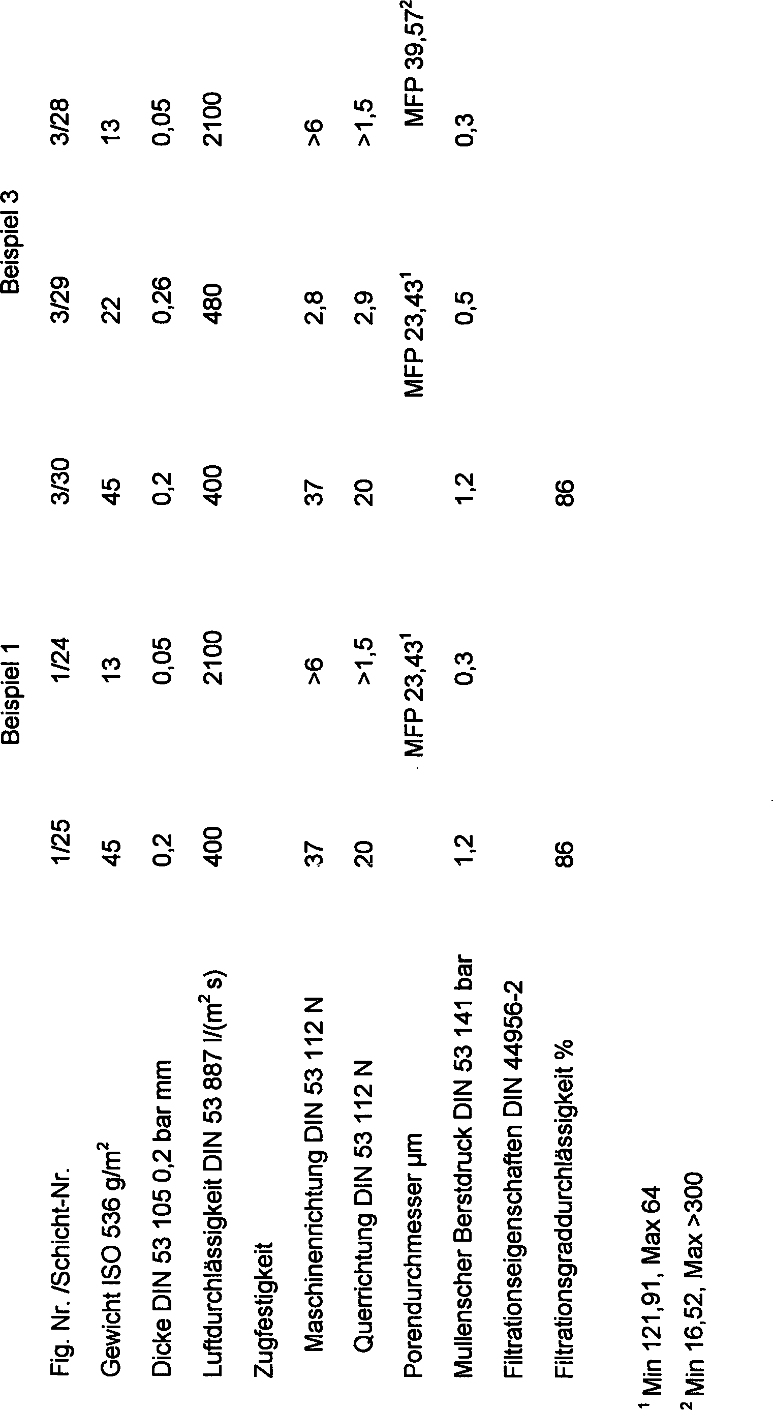


Claims (21)
Applications Claiming Priority (10)
| Application Number | Priority Date | Filing Date | Title |
|---|---|---|---|
| US8503298P | 1998-05-11 | 1998-05-11 | |
| US85032P | 1998-05-11 | ||
| US9603998P | 1998-08-11 | 1998-08-11 | |
| US96039P | 1998-08-11 | ||
| US10614398P | 1998-10-29 | 1998-10-29 | |
| US106143P | 1998-10-29 | ||
| US306880 | 1999-05-07 | ||
| US09/306,883 US6171369B1 (en) | 1998-05-11 | 1999-05-07 | Vacuum cleaner bag construction and method of operation |
| US09/306,880 US6183536B1 (en) | 1998-05-11 | 1999-05-07 | Enhanced performance vacuum cleaner bag and method of operation |
| US306883 | 1999-05-07 |
Publications (2)
| Publication Number | Publication Date |
|---|---|
| DE69910660D1 DE69910660D1 (en) | 2003-10-02 |
| DE69910660T2 true DE69910660T2 (en) | 2004-06-17 |
Family
ID=27536388
Family Applications (2)
| Application Number | Title | Priority Date | Filing Date |
|---|---|---|---|
| DE69910660T Revoked DE69910660T2 (en) | 1998-05-11 | 1999-05-11 | Dust filter bag for a vacuum cleaner or filter, and method for filtering a gas |
| DE69912653T Revoked DE69912653T2 (en) | 1998-05-11 | 1999-05-11 | Dust filter bag for a vacuum cleaner |
Family Applications After (1)
| Application Number | Title | Priority Date | Filing Date |
|---|---|---|---|
| DE69912653T Revoked DE69912653T2 (en) | 1998-05-11 | 1999-05-11 | Dust filter bag for a vacuum cleaner |
Country Status (19)
| Country | Link |
|---|---|
| EP (1) | EP0960645B1 (en) |
| JP (1) | JP2002514447A (en) |
| CN (2) | CN1306451A (en) |
| AT (2) | ATE248014T1 (en) |
| AU (1) | AU753631B2 (en) |
| BR (1) | BR9910389A (en) |
| CA (1) | CA2331636A1 (en) |
| CZ (1) | CZ20004184A3 (en) |
| DE (2) | DE69910660T2 (en) |
| DK (2) | DK0960645T3 (en) |
| HU (1) | HU224280B1 (en) |
| IL (1) | IL139539A0 (en) |
| MX (1) | MXPA00011001A (en) |
| NO (2) | NO322853B1 (en) |
| NZ (1) | NZ507746A (en) |
| PL (2) | PL191581B1 (en) |
| PT (2) | PT960645E (en) |
| TR (1) | TR200003335T2 (en) |
| WO (1) | WO1999058041A2 (en) |
Cited By (4)
| Publication number | Priority date | Publication date | Assignee | Title |
|---|---|---|---|---|
| DE202005007503U1 (en) * | 2005-05-12 | 2006-09-21 | Melitta Haushaltsprodukte Gmbh & Co. Kg | filter bag |
| DE102011086104A1 (en) * | 2011-11-10 | 2013-05-16 | Mahle International Gmbh | filter material |
| WO2019158775A1 (en) | 2018-02-19 | 2019-08-22 | Twe Gmbh & Co. Kg | Filter medium |
| DE102019131364A1 (en) * | 2019-11-20 | 2021-05-20 | Wolf Pvg Gmbh & Co. Kommanditgesellschaft | Vacuum cleaner bags and method of making a vacuum cleaner bag |
Families Citing this family (95)
| Publication number | Priority date | Publication date | Assignee | Title |
|---|---|---|---|---|
| DE102004009956A1 (en) | 2004-03-01 | 2005-09-29 | Eurofilters N.V. | Adsorbent for dust collection filter, dust collection filter and method for odor adsorption |
| DE19935355A1 (en) | 1999-01-07 | 2000-07-13 | Vorwerk Co Interholding | Dust filter bag for a vacuum cleaner |
| EP1171220B1 (en) * | 1999-04-19 | 2003-07-23 | FILTERWERK MANN + HUMMEL GmbH | Multilayer filter element |
| DE19920983C5 (en) † | 1999-05-06 | 2004-11-18 | Fibermark Gessner Gmbh & Co. Ohg | Two-layer or multi-layer filter medium for air filtration and filter element made from it |
| DE20013364U1 (en) * | 2000-08-03 | 2001-02-08 | Branofilter GmbH, 90599 Dietenhofen | Filter bag |
| US6649547B1 (en) | 2000-08-31 | 2003-11-18 | Kimberly-Clark Worldwide, Inc. | Integrated nonwoven laminate material |
| DE10051186B4 (en) | 2000-10-16 | 2005-04-07 | Fibermark Gessner Gmbh & Co. Ohg | Dust filter bag with highly porous carrier material layer |
| DE10109304C5 (en) * | 2001-02-26 | 2009-07-16 | Sandler Ag | Textured, voluminous metblown fleece |
| DE10120223B4 (en) * | 2001-04-24 | 2005-08-25 | Carl Freudenberg Kg | Multi-layer air filter and its use |
| DE10221694B4 (en) | 2002-05-16 | 2018-07-12 | Branofilter Gmbh | Multi-layer filter construction, use of such a multi-layer filter assembly, dust filter bag, bag filter bag, pleated filter, surface exhaust filter and air filter for motor vehicles |
| EP1426090B1 (en) * | 2002-12-06 | 2018-09-19 | Eurofilters N.V. | Non-woven layer for a filter and composite layer incorporating said non-woven layer |
| DK1415699T3 (en) * | 2002-12-06 | 2004-09-20 | Eurofilters Nv | Filter medium for a vacuum cleaner bag |
| US7051883B2 (en) | 2003-07-07 | 2006-05-30 | Reemay, Inc. | Wetlaid-spunbond laminate membrane support |
| DE10359948A1 (en) | 2003-12-19 | 2005-07-14 | Eurofilters N.V. | Dust-collecting filter and method for prolonging the service life of dust-collecting filters |
| BRPI0418727A (en) * | 2004-04-06 | 2007-09-11 | Corovin Gmbh | spinning nonwoven from polymer fibers and their application |
| US7959714B2 (en) | 2007-11-15 | 2011-06-14 | Cummins Filtration Ip, Inc. | Authorized filter servicing and replacement |
| US7674425B2 (en) | 2005-11-14 | 2010-03-09 | Fleetguard, Inc. | Variable coalescer |
| US20070062886A1 (en) | 2005-09-20 | 2007-03-22 | Rego Eric J | Reduced pressure drop coalescer |
| US8114183B2 (en) | 2005-09-20 | 2012-02-14 | Cummins Filtration Ip Inc. | Space optimized coalescer |
| US7828869B1 (en) | 2005-09-20 | 2010-11-09 | Cummins Filtration Ip, Inc. | Space-effective filter element |
| DE102005049118B3 (en) * | 2005-10-14 | 2007-02-01 | Papierverarbeitung Görlitz GmbH | Dust filter bag for vacuum cleaner with a layer connected between two bag walls only in one direction |
| US8231752B2 (en) | 2005-11-14 | 2012-07-31 | Cummins Filtration Ip Inc. | Method and apparatus for making filter element, including multi-characteristic filter element |
| DE102005054903B3 (en) * | 2005-11-17 | 2007-03-22 | Fibermark Gessner Gmbh & Co. | Dust filter bag, especially for vacuum cleaners, has an inflow layer with a filtration layer bonded to the outflow side of it in at least a three-layer structure for the separation of fine and coarse dust |
| AU2006316799B2 (en) | 2005-11-22 | 2011-10-13 | Eurofilters Holding N.V. | Vacuum cleaner filter bag and use of said bag |
| EP1787561B1 (en) | 2005-11-22 | 2013-04-17 | Eurofilters Holding N.V. | Vacuum cleaner dust bag with closure means |
| EP1787564B1 (en) | 2005-11-22 | 2014-10-22 | Eurofilters Holding N.V. | Holding plate with a deflection device for a vacuum cleaner dust bag |
| RU2405402C2 (en) | 2005-11-22 | 2010-12-10 | Еврофильтерс Холдинг Н.В. | Bag filter for vacuum cleaner with closure device and vacuum cleaner to post specified filter |
| EP1958561B1 (en) | 2005-11-22 | 2013-06-19 | Eurofilters Holding N.V. | Vacuum cleaner filter bag |
| DE102005059214B4 (en) | 2005-12-12 | 2007-10-25 | Eurofilters N.V. | Filter bag for a vacuum cleaner |
| DE102006017553B3 (en) * | 2006-04-13 | 2007-12-27 | Eurofilters N.V. | Filter bag for a vacuum cleaner |
| DK2012640T3 (en) | 2006-04-25 | 2010-11-01 | Eurofilters Holding Nv | Holding plate for a vacuum cleaner filter bag |
| ES2361118T3 (en) | 2006-11-03 | 2011-06-14 | Eurofilters Holding N.V. | ANTIBACTERIAL VACUUM FILTER BAG. |
| DE202006018863U1 (en) * | 2006-12-12 | 2008-04-17 | Mann+Hummel Gmbh | Filter element with activated carbon coating |
| DE202006018865U1 (en) * | 2006-12-12 | 2008-05-15 | Mann+Hummel Gmbh | Multilayer filter element |
| ES2319682T3 (en) | 2006-12-15 | 2009-05-11 | Eurofilters Holding N.V. | FILTER DUST VACUUM BAG WITH A GUIDING DEVICE. |
| DE202007005848U1 (en) * | 2007-04-20 | 2008-08-21 | Wolf Pvg Gmbh & Co. Kg | Dust bags |
| DE102007027299B4 (en) * | 2007-06-11 | 2009-02-26 | Johns Manville Europe Gmbh | Filter, process for its production, its use and filter modules |
| DE502007006501D1 (en) | 2007-07-06 | 2011-03-31 | Eurofilters Holding Nv | Vacuum cleaner filter bag |
| DK2011556T4 (en) | 2007-07-06 | 2017-02-27 | Eurofilters Holding Nv | Vacuum cleaner filter bag |
| WO2009010408A1 (en) * | 2007-07-16 | 2009-01-22 | Nv Bekaert Sa | A filter medium |
| PL2025278T3 (en) | 2007-08-17 | 2009-09-30 | Eurofilters Holding Nv | Vacuum cleaner filter bag |
| ES2440722T3 (en) | 2008-03-07 | 2014-01-30 | Eurofilters Holding N.V. | Vacuum cleaner filter bag |
| DE202008017637U1 (en) | 2008-09-04 | 2010-03-25 | Branofilter Gmbh | Dust filter bag device for a vacuum cleaner |
| DE202008016669U1 (en) * | 2008-12-17 | 2009-03-05 | Wolf Pvg Gmbh & Co. Kg | Vacuum cleaner bag and vacuum cleaner |
| DE102009006583A1 (en) * | 2009-01-29 | 2010-06-17 | Neenah Gessner Gmbh | Multi-layer filter material for liquid filtration, for manufacturing filter element, has three layers, where former layer is of wet fleece made of cellulose or synthetic fibers or mixture |
| DE202009003669U1 (en) * | 2009-03-17 | 2010-08-12 | Mann+Hummel Gmbh | filter element |
| DE102010007553A1 (en) * | 2009-05-14 | 2010-11-18 | Sms Siemag Ag | Filter fabric for a band filter |
| DE202009019156U1 (en) | 2009-06-19 | 2017-04-20 | Eurofilters N.V. | Flat bag for vacuum cleaner |
| DK3443880T3 (en) | 2009-06-19 | 2021-07-26 | Eurofilters Nv | Flat bag for vacuum cleaner |
| ES2549756T3 (en) | 2009-06-19 | 2015-11-02 | Eurofilters N.V. | Flat bag for dust vacuum with at least two diffusers |
| ES2607032T3 (en) | 2009-06-24 | 2017-03-28 | Eurofilters N.V. | Solid bottom filter bag for dust vacuum |
| DE102009038230A1 (en) * | 2009-08-20 | 2011-02-24 | Heinrich Essers Gmbh & Co. Kg | Solid filter, especially for a vacuum cleaner, and vacuum cleaner with a solid filter |
| DK2311358T3 (en) | 2009-10-19 | 2016-02-15 | Eurofilters Holding Nv | A holder plate for a vacuum cleaner filter bag |
| EP2311360B1 (en) * | 2009-10-19 | 2014-09-03 | Eurofilters Holding N.V. | Vacuum cleaner filter bag |
| PL2311359T3 (en) | 2009-10-19 | 2016-10-31 | Vacuum cleaner filter bag | |
| DE102010011512A1 (en) * | 2010-03-12 | 2011-09-15 | Mann+Hummel Gmbh | Filter medium of a filter element, filter element and method for producing a filter medium |
| DK2662010T3 (en) | 2010-03-19 | 2014-10-06 | Eurofilters Holding Nv | Vacuum cleaner filter bag |
| DE102010049425A1 (en) * | 2010-10-23 | 2012-04-26 | Gea Heat Exchangers Gmbh | Nonwoven storage filter, useful for general room and process air technology, preferably for bag filters of air conditioners, comprises fibers of polyolefin and/or polyester |
| BR112013004279B1 (en) | 2010-08-23 | 2021-01-05 | Fiberweb Holdings Limited | non-woven weave and fibers with electret properties, their manufacturing processes and their use |
| DE202010013622U1 (en) | 2010-09-27 | 2010-12-23 | Sandler Ag | Multi-layer filter construction |
| DE102010046567A1 (en) | 2010-09-27 | 2012-03-29 | Sandler Ag | Multi-layer filter construction |
| CN102551604A (en) * | 2010-12-16 | 2012-07-11 | 莱克电气股份有限公司 | Dust bag for dust collector |
| JP5977525B2 (en) * | 2011-01-19 | 2016-08-24 | 株式会社Nbcメッシュテック | Surface filtration bag filter |
| PL2502536T3 (en) | 2011-03-22 | 2019-06-28 | Eurofilters N.V. | Ecologically efficient device for vacuum cleaning |
| DE102011014682A1 (en) | 2011-03-22 | 2012-09-27 | Eurofilters Holding N.V. | Device for vacuuming with vacuum cleaner and filter bag |
| ES2445747T3 (en) * | 2011-03-22 | 2014-03-05 | Eurofilters Holding N.V. | Device for dust extraction with vacuum cleaner and filter bag |
| CN103211555B (en) * | 2012-01-19 | 2016-02-03 | 天佑电器(苏州)有限公司 | There is the dust catcher of high-temperature-resfilter filter system |
| PL3072430T3 (en) | 2012-03-22 | 2017-10-31 | Eurofilters Holding Nv | Device for vacuum cleaning with a vacuum cleaning device and filter bag |
| DE102012010307B4 (en) * | 2012-05-24 | 2021-07-08 | Neenah Gessner Gmbh | Multi-layer filter material for liquid filtration and a filter element made from it |
| CN103046231A (en) * | 2012-06-22 | 2013-04-17 | 浙江朝晖过滤技术股份有限公司 | Melt spinning non-woven material and production method and application thereof |
| JP6053486B2 (en) * | 2012-12-06 | 2016-12-27 | 株式会社ニフコ | filter |
| EP2777795B1 (en) * | 2013-03-15 | 2016-03-09 | Eurofilters Holding N.V. | Vacuum cleaner filter bag |
| US10285549B2 (en) * | 2014-06-03 | 2019-05-14 | Shop Vac Corporation | Wet/dry vacuum bag |
| US10165919B2 (en) * | 2014-06-03 | 2019-01-01 | Shop Vac Corporation | Vacuum bag |
| DE102015103019A1 (en) * | 2015-03-03 | 2016-09-08 | Vorwerk & Co. Interholding Gmbh | Dust pickup system with adsorbent material having Dämmschicht |
| AU2016254003A1 (en) * | 2015-04-30 | 2017-12-07 | Tti (Macao Commercial Offshore) Limited | A dust collection apparatus and a method of producing a dust collection apparatus |
| DK3219237T3 (en) | 2016-03-17 | 2018-07-30 | Eurofilters Holding Nv | Holding plate with improved closure element |
| ES2740995T3 (en) | 2016-03-17 | 2020-02-07 | Eurofilters Nv | Filter bag for dust vacuum cleaner, based on recycled synthetic materials |
| ES2668626T3 (en) | 2016-03-17 | 2018-05-21 | Eurofilters N.V. | Vacuum filter bag with recycled textile materials and / or cotton linters |
| EP3219235B1 (en) | 2016-03-17 | 2021-12-29 | Eurofilters Holding N.V. | Device for a vacuum cleaner filter bag comprising a holding device and a closure device |
| EP3219375B2 (en) | 2016-03-17 | 2024-09-18 | Eurofilters N.V. | Vacuum cleaner filter bag containing dust and/or fibrous recycled material |
| WO2017158025A2 (en) * | 2016-03-17 | 2017-09-21 | Eurofilters N.V. | Vacuum cleaner filter bag with recycled textile materials and/or cotton linters |
| PL3219236T3 (en) | 2016-03-17 | 2022-01-31 | Eurofilters Holding N.V. | Holding plate with improved closure |
| DE202016008752U1 (en) | 2016-10-06 | 2019-06-17 | Eurofilters N.V. | Vacuum cleaner filter bag with recycled textile materials and / or cotton linters |
| ES2742406T3 (en) | 2016-10-06 | 2020-02-14 | Eurofilters Nv | Vacuum cleaner filter bags with recycled textile materials and / or cotton linters |
| PL3354178T3 (en) | 2017-01-31 | 2022-03-21 | Eurofilters Holding N.V. | Floor vacuum cleaner |
| DK3357392T3 (en) | 2017-02-07 | 2021-10-11 | Eurofilters Holding Nv | Holding plate for a vacuum cleaner filter bag with closing device |
| CN109306637A (en) * | 2017-07-26 | 2019-02-05 | 中轻特种纤维材料有限公司 | The manufacturing technology of high efficiency vacuum cleaner dust collecting sleeve paper |
| EP3530171B1 (en) | 2018-02-23 | 2021-04-07 | Eurofilters Holding N.V. | Holding plate with sealing element |
| EP3530170B1 (en) | 2018-02-23 | 2020-05-13 | Eurofilters Holding N.V. | Supporting plate with centring device |
| DE202018102370U1 (en) | 2018-04-27 | 2018-05-04 | Eurofilters Holding N.V. | Vacuum cleaner filter bag with foil in the area of the holding plate |
| EP3560402B1 (en) | 2018-04-27 | 2022-12-07 | Eurofilters Holding N.V. | Vacuum cleaner filter bag with film in the area of the holding plate |
| EP3909489A1 (en) * | 2020-05-13 | 2021-11-17 | Hilti Aktiengesellschaft | Disposal bag with pressure balancing matrix |
| EP3950087A1 (en) | 2020-08-06 | 2022-02-09 | Eurofilters N.V. | Vacuum cleaner filter bag made from recycled plastics |
| CN116278304A (en) * | 2023-03-31 | 2023-06-23 | 桐乡市健民过滤材料有限公司 | Composite material for high-efficiency high-fastness industrial dust collector filter element and filter element |
Family Cites Families (10)
| Publication number | Priority date | Publication date | Assignee | Title |
|---|---|---|---|---|
| DE3812849C3 (en) * | 1988-04-18 | 1996-03-21 | Gessner & Co Gmbh | Dust filter bag, its manufacture and use |
| US5080702A (en) | 1990-02-15 | 1992-01-14 | Home Care Industries, Inc. | Disposable two-ply filter |
| US5753343A (en) * | 1992-08-04 | 1998-05-19 | Minnesota Mining And Manufacturing Company | Corrugated nonwoven webs of polymeric microfiber |
| US5730923A (en) * | 1992-09-28 | 1998-03-24 | The University Of Tennessee Research Corporation | Post-treatment of non-woven webs |
| US5647881A (en) * | 1995-04-20 | 1997-07-15 | Minnesota Mining And Manufacturing Company | Shock resistant high efficiency vacuum cleaner filter bag |
| DE19544790C2 (en) * | 1995-11-30 | 1998-11-26 | Kirchhoff International Gmbh M | Disposable vacuum cleaner bags |
| DE19606718A1 (en) * | 1996-02-23 | 1997-08-28 | Vorwerk Co Interholding | Multi-layer filter bag |
| US5672188A (en) * | 1996-05-28 | 1997-09-30 | Aaf International | High capacity filter media |
| US5817415A (en) * | 1996-09-12 | 1998-10-06 | E. I. Du Pont De Nemours And Company | Meltblown ionomer microfibers and non-woven webs made therefrom for gas filters |
| DE19731860C1 (en) * | 1997-07-24 | 1999-01-28 | Freudenberg Carl Fa | Dust filter bag |
-
1999
- 1999-05-11 AT AT99401164T patent/ATE248014T1/en not_active IP Right Cessation
- 1999-05-11 DK DK99401164T patent/DK0960645T3/en active
- 1999-05-11 BR BR9910389-3A patent/BR9910389A/en not_active Application Discontinuation
- 1999-05-11 EP EP99401164A patent/EP0960645B1/en not_active Revoked
- 1999-05-11 CA CA002331636A patent/CA2331636A1/en not_active Withdrawn
- 1999-05-11 PL PL344661A patent/PL191581B1/en unknown
- 1999-05-11 AU AU36235/99A patent/AU753631B2/en not_active Ceased
- 1999-05-11 JP JP2000547897A patent/JP2002514447A/en active Pending
- 1999-05-11 NZ NZ507746A patent/NZ507746A/en not_active IP Right Cessation
- 1999-05-11 CZ CZ20004184A patent/CZ20004184A3/en unknown
- 1999-05-11 IL IL13953999A patent/IL139539A0/en unknown
- 1999-05-11 TR TR2000/03335T patent/TR200003335T2/en unknown
- 1999-05-11 PL PL99375457A patent/PL194345B1/en not_active IP Right Cessation
- 1999-05-11 DE DE69910660T patent/DE69910660T2/en not_active Revoked
- 1999-05-11 CN CN99807584A patent/CN1306451A/en active Pending
- 1999-05-11 HU HU0104320A patent/HU224280B1/en not_active IP Right Cessation
- 1999-05-11 PT PT99401164T patent/PT960645E/en unknown
- 1999-05-11 AT AT02018932T patent/ATE253393T1/en not_active IP Right Cessation
- 1999-05-11 MX MXPA00011001A patent/MXPA00011001A/en unknown
- 1999-05-11 WO PCT/IB1999/000896 patent/WO1999058041A2/en not_active Application Discontinuation
- 1999-05-11 DK DK02018932T patent/DK1258277T3/en active
- 1999-05-11 CN CNA2004100957207A patent/CN1618390A/en active Pending
- 1999-05-11 DE DE69912653T patent/DE69912653T2/en not_active Revoked
- 1999-05-11 PT PT02018932T patent/PT1258277E/en unknown
-
2000
- 2000-11-08 NO NO20005639A patent/NO322853B1/en not_active Application Discontinuation
-
2006
- 2006-09-20 NO NO20064254A patent/NO20064254L/en unknown
Cited By (6)
| Publication number | Priority date | Publication date | Assignee | Title |
|---|---|---|---|---|
| DE202005007503U1 (en) * | 2005-05-12 | 2006-09-21 | Melitta Haushaltsprodukte Gmbh & Co. Kg | filter bag |
| DE102011086104A1 (en) * | 2011-11-10 | 2013-05-16 | Mahle International Gmbh | filter material |
| US9592465B2 (en) | 2011-11-10 | 2017-03-14 | Mahle International Gmbh | Filter material |
| WO2019158775A1 (en) | 2018-02-19 | 2019-08-22 | Twe Gmbh & Co. Kg | Filter medium |
| DE102018103682A1 (en) * | 2018-02-19 | 2019-08-22 | Twe Gmbh & Co. Kg | filter media |
| DE102019131364A1 (en) * | 2019-11-20 | 2021-05-20 | Wolf Pvg Gmbh & Co. Kommanditgesellschaft | Vacuum cleaner bags and method of making a vacuum cleaner bag |
Also Published As
Similar Documents
| Publication | Publication Date | Title |
|---|---|---|
| DE69910660T2 (en) | Dust filter bag for a vacuum cleaner or filter, and method for filtering a gas | |
| DE60003431T2 (en) | MULTILAYER FILTER AND METHOD FOR THE PRODUCTION THEREOF | |
| DE60100985T2 (en) | Multi-layer filter and method of making the same | |
| DE10084563B4 (en) | Materials with fibers and pleats in Z-direction and their use | |
| US6183536B1 (en) | Enhanced performance vacuum cleaner bag and method of operation | |
| DE10221694B4 (en) | Multi-layer filter construction, use of such a multi-layer filter assembly, dust filter bag, bag filter bag, pleated filter, surface exhaust filter and air filter for motor vehicles | |
| AU2002240938A1 (en) | Composite filter and method of making the same | |
| EP1277865B1 (en) | Non-woven with regular three-dimensional pattern, process for producing the same and applications | |
| DE29924466U1 (en) | Vacuum cleaner bags and improved vacuum cleaner bags | |
| EP3601655B1 (en) | Spun-bonded fabric material, object comprising a spun-bonded fabric material, filter element, and use thereof | |
| EP1234906A1 (en) | Bulky structured melblown nonwoven web | |
| EP1099787B1 (en) | Fibre mat | |
| DE29924500U1 (en) | Disposable filter bag for vacuum cleaners | |
| DE20122003U1 (en) | Composite filter for vacuum cleaner bag, has prebonded upstream tier and non-prebonded downstream tier such that ratio of absolute pore volume between upstream tier and downstream tier is greater than predetermined value | |
| JPH11179121A (en) | Substrate for filter and filter comprising substrate for filter | |
| DE20023273U1 (en) | Composite filter for e.g. vacuum cleaner bag, comprises several non-prebonded tiers, each comprising filtration material, with tiers bonded together to form unitary stratified structure having boundary surfaces | |
| EP3601657B1 (en) | Filter medium, filter element and use thereof and filter arrangement | |
| AU765699B2 (en) | Vacuum cleaner bag and improved vacuum cleaner bag |
Legal Events
| Date | Code | Title | Description |
|---|---|---|---|
| 8363 | Opposition against the patent | ||
| 8331 | Complete revocation |