EP2311360B1 - Vacuum cleaner filter bag - Google Patents
Vacuum cleaner filter bag Download PDFInfo
- Publication number
- EP2311360B1 EP2311360B1 EP09013176.4A EP09013176A EP2311360B1 EP 2311360 B1 EP2311360 B1 EP 2311360B1 EP 09013176 A EP09013176 A EP 09013176A EP 2311360 B1 EP2311360 B1 EP 2311360B1
- Authority
- EP
- European Patent Office
- Prior art keywords
- vacuum cleaner
- filter bag
- nonwoven
- bag
- cleaner filter
- Prior art date
- Legal status (The legal status is an assumption and is not a legal conclusion. Google has not performed a legal analysis and makes no representation as to the accuracy of the status listed.)
- Active
Links
- 238000003490 calendering Methods 0.000 claims description 12
- 230000035699 permeability Effects 0.000 claims description 10
- 229920000747 poly(lactic acid) Polymers 0.000 claims description 8
- 229920000704 biodegradable plastic Polymers 0.000 claims description 6
- 239000004750 melt-blown nonwoven Substances 0.000 claims description 4
- 230000035515 penetration Effects 0.000 claims description 4
- 239000004743 Polypropylene Substances 0.000 claims description 3
- 229920000642 polymer Polymers 0.000 claims description 3
- -1 polypropylene Polymers 0.000 claims description 3
- 229920001155 polypropylene Polymers 0.000 claims description 3
- 238000002604 ultrasonography Methods 0.000 claims 1
- 239000010410 layer Substances 0.000 description 68
- 239000004745 nonwoven fabric Substances 0.000 description 61
- 229920001410 Microfiber Polymers 0.000 description 12
- 239000003658 microfiber Substances 0.000 description 12
- 238000003466 welding Methods 0.000 description 12
- 239000000463 material Substances 0.000 description 11
- 239000000835 fiber Substances 0.000 description 10
- 238000000034 method Methods 0.000 description 8
- 238000004519 manufacturing process Methods 0.000 description 7
- 238000003825 pressing Methods 0.000 description 7
- 229920003023 plastic Polymers 0.000 description 5
- 239000004033 plastic Substances 0.000 description 5
- FAPWRFPIFSIZLT-UHFFFAOYSA-M Sodium chloride Chemical compound [Na+].[Cl-] FAPWRFPIFSIZLT-UHFFFAOYSA-M 0.000 description 4
- 238000004049 embossing Methods 0.000 description 4
- 238000007711 solidification Methods 0.000 description 4
- 230000008023 solidification Effects 0.000 description 4
- 239000000428 dust Substances 0.000 description 3
- 239000000155 melt Substances 0.000 description 3
- 230000003014 reinforcing effect Effects 0.000 description 3
- 238000000926 separation method Methods 0.000 description 3
- 239000002356 single layer Substances 0.000 description 3
- 238000013461 design Methods 0.000 description 2
- 238000009826 distribution Methods 0.000 description 2
- 229920001610 polycaprolactone Polymers 0.000 description 2
- 239000004632 polycaprolactone Substances 0.000 description 2
- 239000011780 sodium chloride Substances 0.000 description 2
- 238000003860 storage Methods 0.000 description 2
- 241000894006 Bacteria Species 0.000 description 1
- 238000004026 adhesive bonding Methods 0.000 description 1
- 238000006065 biodegradation reaction Methods 0.000 description 1
- 239000012876 carrier material Substances 0.000 description 1
- 238000006243 chemical reaction Methods 0.000 description 1
- 239000003795 chemical substances by application Substances 0.000 description 1
- 150000001875 compounds Chemical class 0.000 description 1
- 238000007596 consolidation process Methods 0.000 description 1
- 230000000694 effects Effects 0.000 description 1
- 238000002474 experimental method Methods 0.000 description 1
- 238000001125 extrusion Methods 0.000 description 1
- 239000004744 fabric Substances 0.000 description 1
- 238000001914 filtration Methods 0.000 description 1
- 239000006260 foam Substances 0.000 description 1
- 238000010191 image analysis Methods 0.000 description 1
- 229910052500 inorganic mineral Inorganic materials 0.000 description 1
- 238000005259 measurement Methods 0.000 description 1
- 238000002844 melting Methods 0.000 description 1
- 230000008018 melting Effects 0.000 description 1
- 239000011707 mineral Substances 0.000 description 1
- 239000002121 nanofiber Substances 0.000 description 1
- 239000002245 particle Substances 0.000 description 1
- 229920000728 polyester Polymers 0.000 description 1
- 239000004626 polylactic acid Substances 0.000 description 1
- 230000001681 protective effect Effects 0.000 description 1
- 239000011241 protective layer Substances 0.000 description 1
- 238000012360 testing method Methods 0.000 description 1
Images

Classifications
-
- A—HUMAN NECESSITIES
- A47—FURNITURE; DOMESTIC ARTICLES OR APPLIANCES; COFFEE MILLS; SPICE MILLS; SUCTION CLEANERS IN GENERAL
- A47L—DOMESTIC WASHING OR CLEANING; SUCTION CLEANERS IN GENERAL
- A47L9/00—Details or accessories of suction cleaners, e.g. mechanical means for controlling the suction or for effecting pulsating action; Storing devices specially adapted to suction cleaners or parts thereof; Carrying-vehicles specially adapted for suction cleaners
- A47L9/10—Filters; Dust separators; Dust removal; Automatic exchange of filters
- A47L9/14—Bags or the like; Rigid filtering receptacles; Attachment of, or closures for, bags or receptacles
Definitions
- the invention relates to a vacuum cleaner filter bag with a bag wall.
- the invention particularly relates to a disposable filter bag.
- Nonwoven fabric vacuum cleaner bags typically have a bag wall made up of multiple layers of filter material.
- the filter material layers may be, for example, layers of filter paper or nonwoven fabric.
- different filter material layers are combined.
- the different filter material layers can be connected to each other or lie loosely on each other.
- a compound of the layers can be done for example by gluing, welding (calendering) or needling.
- a multilayer filter bag is for example from the US 4,589,894 known.
- the individual filter material layers can have different functions.
- protective layers, capacitance layers, fine filter layers and reinforcing layers can be combined.
- a protective or reinforcing layers are thermally bonded filament spunbonded nonwovens (EP 0 161 790 ), thermally bonded nonwoven fabrics ( US 5,647,881 ), Networks ( EP 2 011 556 or EP 2 011 555 ) or perforated films ( EP 1 795 248 ) used.
- the fine filter layers used are microfiber spunbonded nonwovens (eg meltblown nonwovens) (see, for example, US Pat. EP 0 161 790 ). Nanofiber webs have been proposed as Feinstfilterlagen ( DE 199 19 809 ).
- Coarse filter layers can be made, for example, of nonwoven fabrics (carded or aerodynamically laid) or filamentviasives ( EP 0 960 645 ) or of loose staple fibers ( DE 10 2005 059 214 ) consist. Foam has also been proposed as a material for capacity layers ( DE 10 2004 020 555 ).
- a dust filter consisting of two layers known, wherein a layer thereby has a very high air permeability and carrier function.
- the carrier material is paper with high air permeability.
- the second layer consists of a non-woven, ie of loose and non-solidified fibers.
- a multi-ply vacuum cleaner bag having at least one layer responsible for the particle capture activity.
- the DE 195 44 790 also claims that if this active layer was strong enough to withstand the stresses of manufacture and use, further layers could be dispensed with.
- this active layer has a basis weight of less than 20 g / m 2 and a fiber diameter of about 1 micron. With this grammage and fineness, however, a sufficiently stable material can not actually be produced. In operation, bags of such a material would rupture immediately, so that in fact the vacuum cleaner bags known from this document are always multi-layered.
- the object underlying the present invention is to provide a vacuum cleaner filter bag, on the one hand has a sufficient Abscheidebericht and on the other hand can be produced inexpensively. This object is achieved by a vacuum cleaner filter bag according to claim 1.
- the invention provides a vacuum cleaner filter bag having a bag wall, the bag wall comprising precisely one nonwoven fabric layer in the form of a melt-spun microfiber nonwoven layer, and having the features contained in claim 1.
- the present inventors have found that it is possible to produce a vacuum cleaner filter bag having just one nonwoven fabric layer in the form of a melt-spun microfiber nonwoven layer, ie, a nonwoven fabric layer of melt spun microfiber nonwoven fabric having sufficient separation performance. Since exactly one nonwoven fabric layer and not several nonwoven fabric layers are provided for the bag wall, no different processes for the production of nonwoven fabric are required and a connection of different nonwoven fabric layers can be dispensed with. As a result, the vacuum cleaner filter bag can be produced more cost-effectively than multi-layer vacuum cleaner filter bags.
- nonwoven is defined as ISO standard IS09092: 1988 or CEM standard EN29092 used.
- nonwoven fabric or nonwoven and nonwoven fabric in the field of production of nonwovens such follows each other delimited and to understand so in the sense of the present invention.
- To produce a nonwoven fabric fibers and / or filaments are used.
- the loose or loose and still unbound fibers and / or filaments are referred to as fleece or nonwoven web.
- non-woven binding step such a nonwoven fabric finally forms a nonwoven which has sufficient strength to be wound into rolls, for example.
- a nonwoven fabric is self-supporting by the solidification.
- the nonwoven layer corresponds to a layer of a nonwoven fabric which is an extrusion nonwoven fabric, namely a melt spun microfiber spunbonded fabric ("meltblown" nonwoven fabric).
- a melt spun microfiber spunbonded fabric melt spun microfiber spunbonded fabric
- the nonwoven layer according to the invention is a melt spun microfiber spunbonded nonwoven layer.
- the bag wall comprises exactly one filter-active layer, which corresponds exactly to a filter-active layer of the nonwoven fabric layer.
- a filter-active layer here for the filtering of the air stream to be filtered relevant location is referred to.
- the bag wall may also comprise a net.
- the net can serve for the aesthetic design, for example for color design, of the filter bag.
- the net can also serve to improve the stability of the filter bag.
- the network may be, for example, an extruded net or a woven net.
- the mesh may have a mesh size of at least 1 mm, in particular at least 3 mm.
- the bag wall may consist of a nonwoven layer in the form of a melt-spun microfiber nonwoven layer.
- the vacuum cleaner filter bag can be a single-layered filter bag, with the single layer corresponding to the nonwoven layer, ie the layer of melt-spun microfiber nonwoven fabric.
- no support layer or reinforcing layer is provided for the nonwoven fabric layer in this case.
- the nonwoven layer can be designed to withstand the usual stresses of manufacture and use.
- the nonwoven fabric is a calendered nonwoven, in particular a thermally or ultrasonically calendered nonwoven.
- the initially unconsolidated web can be passed between two rolls, of which at least one of the fibers is heated to the melting temperature of the web forming fibers. At least one of the Calender rolls can have elevations. As a result, melt zone areas or weld points can be formed.
- Ultrasonic calendering or ultrasonic solidification is based on the conversion of electrical energy into mechanical vibration energy. This hardening horns are put into vibration, wherein the fibers are softened at the intersection points in the fleece at the vibration points and welded together. As a result, welds can be formed.
- the welds themselves may be formed in different geometries. Thus, punctiform, linear, star-shaped, circular, elliptical, square or bar-shaped welded joints can be formed.
- the pressing surface portion of the calendered nonwoven fabric is 3% to 50%, in particular 10% to 30%. This means that a roller engraving used for calendering the nonwoven fabric has a pressing surface portion of 3% to 50%, in particular 10% to 30%.
- the nonwoven fabric has a number density of weld points of 5 / cm 2 to 50 / cm 2 , in particular 15 / cm 2 to 40 / cm 2 , on.
- the number density is referred to here as the number of spot welds per unit area.
- Such a calendered nonwoven fabric may have sufficient strength for use as a bag wall of a vacuum cleaner filter bag.
- the welds or welds can be evenly distributed, in particular at equal intervals, or even unevenly over the entire surface of the bag wall.
- the welds may be disposed on the nonwoven fabric in the machine direction or at an angle greater than 0 ° and less than 180 ° to the machine direction.
- the welds can also be arranged transversely to the machine direction, ie at an angle of 90 ° to the machine direction.
- the nonwoven fabric layer has a basis weight of 30 g / m 2 to 200 g / m 2 , in particular 40 g / m 2 to 150 g / m 2 , in particular 120 g / m 2 .
- the nonwoven fabric layer has a maximum machine direction tensile force of greater than 40N, especially greater than 60N. It may also have a maximum tensile force in the transverse direction of more than 30 N, in particular more than 50 N.
- the thickness of the nonwoven fabric layer may be between 0.2 mm and 1 mm, in particular between 0.4 mm and 0.8 mm.
- the nonwoven fabric layer can have an air permeability of from 40 l / (m 2 s) to 500 l / (m 2 s), in particular from 50 l / (m 2 s) to 300 l / (m 2 s), in particular of 80 l / ( m 2 s) to 200 l / (m 2 s).
- the penetration of the nonwoven layer may be less than 60%, in particular less than 50%, in particular less than 15%.
- the material may be a polymer, in particular polypropylene, and / or polyester and / or a biodegradable plastic, in particular PLA (polylactic acid, polylactide) and / or polycaprolactone (PCL).
- the nonwoven layer can only consist of plastic, in particular of biodegradable plastic.
- Biodegradable plastics can be removed from the environment through biodegradation and fed into the mineral material cycle.
- biodegradable plastics refer to plastics that meet the criteria of the European standards EN 13432 and / or EN 14995.
- Biodegradable plastics which can be processed into nonwovens, for example, from the US 6,207,601 and the EP 0 885 321 known.
- the nonwoven layer can be electrostatically charged.
- the fibers may be electrostatically charged prior to solidification and / or the nonwoven fabric, ie after solidification.
- the nonwoven layer can be electrostatically charged by a corona process. In doing so, the web is centered in an approximately 3.8 cm (1.5 inches) to 7.6 cm (3 inches) wide area between two DC voltage electrodes for corona discharge. In this case, one of the electrodes can have a positive DC voltage of 20 to 30 kV while the second electrode has a negative DC voltage of 20 to 30 kV.
- the nonwoven layer may be formed by a method according to the teaching of US 5,401,446 be electrostatically charged.
- the vacuum cleaner filter bag may be a flat bag. Alternatively, the vacuum cleaner filter bag may also be a block bottom bag.
- the vacuum cleaner filter bag may include an inflow port through which the air to be cleaned flows into the filter bag.
- the filter bag may further comprise a holding plate, which serves to fix the vacuum cleaner filter bag in a chamber of a vacuum cleaner, and is arranged in the region of the inflow opening.
- the retaining plate can in particular be made of a plastic.
- the holding plate can be connected to the bag wall and have a through hole in the region of the inflow opening.
- the bag wall may include a front and a back, which are interconnected by a circumferential weld.
- the front and back can be rectangular, square or circular.
- the front and back may consist of a nonwoven fabric layer described above.
- the vacuum cleaner filter bag may be a disposable vacuum cleaner bag.
- the abovementioned parameters can be adapted in particular to the size and / or the intended use of the vacuum cleaner filter bag.
- the air permeability is determined according to DIN EN IS09237: 1995-12. In particular, a differential pressure of 200 Pa and a test area of 20 cm 2 are used . For the Determination of air permeability, the air permeability tester FX3300 Texttest AG was used.
- the basis weight is determined according to DIN EN 29073-1: 1992-08.
- the method according to standard DIN EN ISO 9073-2: 1997-02 is used, using method A.
- the determination of the maximum tensile force is carried out in accordance with DIN EN29073-3: 1992-08. In particular, a strip width of 50 mm is used.
- Penetration NaCl permeability
- TSI 8130 tester a TSI 8130 tester.
- 0.3 ⁇ m sodium chloride is used at 86 L / min.
- the measurement of the number density of the welding points is carried out as follows. First, five mutually non-overlapping faces of the bag wall are selected, each of the faces is 10 cm 2 in size and is completely enclosed by flow-through surface of the bag wall. In other words, none of the partial area directly adjoins the holding plate, the inflow opening and / or possibly existing weld seams. Each of the faces is surrounded by a square with a side of 3.16 cm. All partial surfaces may be arranged on the front side or the rear side of the filter bag, or one or more partial surfaces on the front side and one or more partial surfaces on the rear side.
- the welding spots arranged on the partial surface are then counted, and the ratio of the number of welding points to the total surface of the partial surface is formed for each of the partial surfaces. In other words, for each of the patches, the number of welds is divided by 10 cm 2 .
- a welding point is arranged on the subarea when at least part of the surface of the welding point lies within the square surrounding the subarea.
- the arithmetic mean is then formed, i. the five values are added and then divided by five.
- the value thus obtained corresponds to the number density of the weld spots of the nonwoven fabric layer.
- the determination of the pressing surface portion of the welding points is carried out as follows. First, five non-overlapping partial surfaces of the bag wall are selected, wherein each of the faces is 10 cm 2 in size and is completely enclosed by the flow-through surface of the bag wall. In other words, none of the partial area directly adjoins the holding plate, the inflow opening and / or possibly existing weld seams. Each of the faces is surrounded by a square with a side of 3.16 cm. All partial surfaces may be arranged on the front side or the rear side of the filter bag, or one or more partial surfaces on the front side and one or more partial surfaces on the rear side.
- the total area of the welding spots that is to say the sum of the welding spot areas arranged on the sub-area, is then determined.
- the total area of the spot welds is determined by means of a measuring microscope and / or by means of image analysis.
- the ratio of the total area of the welding spots to the total area of the partial area is then formed.
- the total area of the welds is divided by 10 cm 2 .
- the arithmetic mean is then formed, ie the five values are added and then divided by five. The value thus obtained corresponds to the pressing surface portion of the welding points of the nonwoven fabric layer.
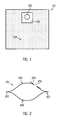
- Fig. 1 shows the schematic structure of an exemplary vacuum cleaner filter bag 101.
- the filter bag 101 comprises an inflow opening 102 through which the air to be filtered flows into the filter bag 101.
- the exemplary filter bag 101 also includes a holding plate 103, which serves to fix the vacuum cleaner filter bag 101 in a chamber of a vacuum cleaner.
- the holding plate 103 is made of a plastic.
- FIG. 1 the bag wall 104, wherein the bag wall 104 comprises exactly one nonwoven fabric layer in the form of a melt spun microfiber nonwoven layer.
- the exemplary filter bag 101 is formed as a flat bag.
- the filter bag 101 is a single-layer, consisting of a nonwoven fabric layer of melt-spun microfiber spunbonded nonwoven fabric ("meltblown" nonwoven fabric), which was solidified pointwise by means of thermal calendering.
- the nonwoven fabric layer of the exemplary filter bag 101 is made of PLA (polylactide).
- PLA polylactide
- PLA can be purchased from Galactic Laboratories (Belgium), Cargill Dow Polymers LLC, Toyobo (Japan), Dai-Nippon, etc.
- the basis weight or basis weight of the exemplary filter bag 101 is 85 g / m 2 .
- the embossed pattern of the bag wall 104 has a density of 25 spots per cm 2 .
- the pressing surface portion of the embossing pattern is 17%.
- the pattern may be, for example, a pattern arranged at an angle of 45 ° to the machine direction.
- meltblown microfiber spunbonded nonwoven produced in this way achieves sufficient strength with satisfactory separation efficiency and air permeability.
- a single-layer filter bag such as those associated with FIG. 1 described exemplary filter bag 101, can be produced or sold more cheaply and therefore is better suited for such a short service life.
- FIG. 2 shows a cross section of an exemplary filter bag 201.
- the filter bag 201 includes a front 205 and a back 206, which are interconnected by a circumferential weld 207.
- an inflow opening 202 is provided, through which the sucked air can flow into the filter bag 201.
- a holding plate 203 which serves to fix the vacuum cleaner filter bag 201 in a chamber of a vacuum cleaner, is arranged in the region of the inflow opening 202 and connected to the bag wall of the filter bag 201.
- a cutout 308 of the bag wall of an exemplary filter bag is shown in FIG Fig. 3 shown.
- the exemplary cutout 308 of the bag wall has a plurality of welds or welds 309 which have been formed by calender thermal consolidation on an embossing calender.
- Weld points 309 correspond to melt zone areas.
- the embossing pattern has a density of 25 spots per cm 2 .
- the pressing surface portion of the embossing pattern is 17%.
- the spot welds are distributed uniformly, ie at equal intervals, over the exemplary cutout 308 of the bag wall.
- the weld spots can be distributed over the entire surface of the bag wall through the entire surface.
- Full surface does not mean in this context that all the fibers are completely connected to each other, for example, fused, resulting in a film. Rather, it means that the nonwoven layer is welded at a plurality of discrete locations, these locations being evenly distributed over the entire area of the nonwoven layer. The locations may be predetermined, for example in the case of a dot or gravure calender.
- Nonwoven fabric 1 Nonwoven fabric 2
- Nonwoven fabric 3 Nonwoven fabric 4
- Pressing area [%] none none 20 17 Welding points [points / cm 2 ] none none 25
- Areal mass [g / m 2 ] 85 100 86 89
- Thickness [mm] 1.2 0.99 0.65 0.62
- Air permeability [l / (m 2 s)] 210 213 130 134
- 86 60 Penetration (TSI 8130, 0.3 ⁇ m, 86 l / min) [%] 5.5 (corona charged) 48 (uncharged) 44 (uncharged) 46 (uncharged) 16 (corona charged)
- All nonwovens shown in the table are made of polypropylene and are meltblown nonwovens, ie spun-bonded microfiber nonwovens.
- the exemplary nonwoven fabric 3 was in particular biaxially stretched.
Description
Die Erfindung betrifft einen Staubsaugerfilterbeutel mit einer Beutelwand. Die Erfindung betrifft insbesondere einen Wegwerffilterbeutel.The invention relates to a vacuum cleaner filter bag with a bag wall. The invention particularly relates to a disposable filter bag.
Staubsaugerfilterbeutel aus Vliesstoffen weisen üblicherweise eine Beutelwand aus mehreren Filtermateriallagen auf. Bei den Filtermateriallagen kann es sich beispielsweise um Lagen aus Filterpapier oder Vliesstoff handeln. Um die gewünschten Eigenschaften hinsichtlich Abscheideleistung, Staubspeicherfähigkeit (Kapazität) und mechanischer Festigkeit zu erreichen werden unterschiedliche Filtermateriallagen kombiniert. Die unterschiedlichen Filtermateriallagen können dabei miteinander verbunden sein oder lose aufeinander liegen. Eine Verbindung der Lagen kann beispielsweise durch Kleben, Schweißen (Kalandrieren) oder Vernadeln erfolgen. Ein mehrlagiger Filterbeutel ist beispielsweise aus der
Die einzelnen Filtermateriallagen können dabei unterschiedliche Funktionen haben. Beispielsweise können Schutzlagen, Kapazitätslagen, Feinfilterlagen und Verstärkungslagen kombiniert werden. Als Schutz- oder Verstärkungslagen werden thermisch verfestigte Filamentspinnvliesstoffe (
Aus der
Aus der
Gemäß der Lehre der
Die Fertigung mehrlagiger Staubsaugerfilterbeutel aus mehreren Vliesstofflagen ist jedoch kostenintensiv, da Produktionsanlagen für unterschiedlichste Verfahren zur Vliesstoffherstellung benötigt werden.The production of multi-layer vacuum cleaner filter bag from several nonwoven fabric layers, however, is costly because production equipment for a variety of processes for nonwoven fabric production are needed.
Daher besteht die der vorliegenden Erfindung zugrundeliegende Aufgabe darin, einen Staubsaugerfilterbeutel bereit zu stellen, der einerseits eine ausreichende Abscheideleistung aufweist und andererseits kostengünstig produziert werden kann. Diese Aufgabe wird durch einen Staubsaugerfilterbeutel nach Anspruch 1 gelöst.Therefore, the object underlying the present invention is to provide a vacuum cleaner filter bag, on the one hand has a sufficient Abscheideleistung and on the other hand can be produced inexpensively. This object is achieved by a vacuum cleaner filter bag according to claim 1.
Die Erfindung stellt einen Staubsaugerfilterbeutel mit einer Beutelwand bereit, wobei die Beutelwand genau eine Vliesstofflage in Form einer schmelzgesponnenen Mikrofaservliesstofflage umfasst, und wobei sie die in Anspruch 1 enthaltenen Merkmale aufweist.The invention provides a vacuum cleaner filter bag having a bag wall, the bag wall comprising precisely one nonwoven fabric layer in the form of a melt-spun microfiber nonwoven layer, and having the features contained in claim 1.
Die Anmelder der vorliegenden Erfindung haben festgestellt, dass es möglich ist, einen Staubsaugerfilterbeutel mit genau einer Vliesstofflage in Form einer schmelzgesponnenen Mikrofaservliesstofflage, also einer Vliesstofflage aus schmelzgesponnenen Mikrofaservliesstoff, herzustellen, der eine ausreichende Abscheideleistung aufweist. Da für die Beutelwand genau eine Vliesstofflage und nicht mehrere Vliesstofflagen vorgesehen sind, sind keine unterschiedlichen Verfahren zur Vliesstoffherstellung nötig und ein Verbinden unterschiedlicher Vliesstofflagen kann entfallen. Dadurch kann der Staubsaugerfilterbeutel kostengünstiger hergestellt werden als mehrlagige Staubsaugerfilterbeutel.The present inventors have found that it is possible to produce a vacuum cleaner filter bag having just one nonwoven fabric layer in the form of a melt-spun microfiber nonwoven layer, ie, a nonwoven fabric layer of melt spun microfiber nonwoven fabric having sufficient separation performance. Since exactly one nonwoven fabric layer and not several nonwoven fabric layers are provided for the bag wall, no different processes for the production of nonwoven fabric are required and a connection of different nonwoven fabric layers can be dispensed with. As a result, the vacuum cleaner filter bag can be produced more cost-effectively than multi-layer vacuum cleaner filter bags.
Der Begriff Vliesstoff ("Nonwoven") wird gemäß der Definition nach ISO Standard
Die Vliesstofflage entspricht einer Lage aus einem Vliesstoff, der ein Extrusionsvliesstoff, nämlich ein schmelzgesponnener Mikrofaserspinnvliesstoff ("Meltblown"-Vliesstoff) ist.The nonwoven layer corresponds to a layer of a nonwoven fabric which is an extrusion nonwoven fabric, namely a melt spun microfiber spunbonded fabric ("meltblown" nonwoven fabric).
Die Vliesstofflage ist erfindungsgemäß eine schmelzgesponnene Mikrofaserspinnvliesstofflage.The nonwoven layer according to the invention is a melt spun microfiber spunbonded nonwoven layer.
Die Beutelwand umfasst genau eine filteraktive Lage, wobei die genau eine filteraktive Lage der Vliesstofflage entspricht. Als filteraktive Lage wird hier eine für die Filterung des zu filternden Luftstromes relevante Lage bezeichnet. Die Beutelwand kann außerdem ein Netz umfassen. Das Netz kann zur ästhetischen Gestaltung, beispielsweise zur farblichen Gestaltung, des Filterbeutels dienen. Das Netz kann auch zur Verbesserung der Stabilität des Filterbeutels dienen. Das Netz kann beispielsweise ein extrudiertes Netz oder ein gewebtes Netz sein. Das Netz kann eine Maschenweite von wenigstens 1 mm, insbesondere wenigstens 3 mm, aufweisen.The bag wall comprises exactly one filter-active layer, which corresponds exactly to a filter-active layer of the nonwoven fabric layer. As a filter-active layer here for the filtering of the air stream to be filtered relevant location is referred to. The bag wall may also comprise a net. The net can serve for the aesthetic design, for example for color design, of the filter bag. The net can also serve to improve the stability of the filter bag. The network may be, for example, an extruded net or a woven net. The mesh may have a mesh size of at least 1 mm, in particular at least 3 mm.
Die Beutelwand kann aus einer Vliesstofflage in Form einer schmelzgesponnenen Mikrofaservliesstofflage bestehen. Mit anderen Worten kann der Staubsaugerfilterbeutel ein einlagiger Filterbeutel sein, wobei die einzige Lage der Vliesstofflage, also der Lage aus schmelzgesponnenen Mikrofaservliesstoff, entspricht. Insbesondere ist in diesem Fall keine Stützlage oder Verstärkungslage für die Vliesstofflage vorgesehen. Mit anderen Worten kann die Vliesstofflage derart ausgebildet sein, dass sie den üblichen Beanspruchungen bei Herstellung und Gebrauch standhält.The bag wall may consist of a nonwoven layer in the form of a melt-spun microfiber nonwoven layer. In other words, the vacuum cleaner filter bag can be a single-layered filter bag, with the single layer corresponding to the nonwoven layer, ie the layer of melt-spun microfiber nonwoven fabric. In particular, no support layer or reinforcing layer is provided for the nonwoven fabric layer in this case. In other words, the nonwoven layer can be designed to withstand the usual stresses of manufacture and use.
Der Vliesstoff ist ein kalandrierter Vliesstoff, insbesondere ein thermisch oder mittels Ultraschall kalandrierter Vliesstoff. Zum thermischen Kalandrieren kann das zunächst unverfestigte Vlies zwischen zwei Walzen hindurchgeführt werden, von welchen wenigstens eine auf die Schmelztemperatur der das Vlies bildenden Fasern erhitzt ist. Wenigstens eine der Kalandrierwalzen kann Erhebungen aufweisen. Dadurch können Schmelzzonenbereiche oder Schweißpunkte gebildet werden.The nonwoven fabric is a calendered nonwoven, in particular a thermally or ultrasonically calendered nonwoven. For thermal calendering, the initially unconsolidated web can be passed between two rolls, of which at least one of the fibers is heated to the melting temperature of the web forming fibers. At least one of the Calender rolls can have elevations. As a result, melt zone areas or weld points can be formed.
Ultraschallkalandrierung oder Ultraschallverfestigung beruht auf der Umwandlung elektrischer Energie in mechanische Vibrationsenergie. Dabei werden Verfestigungshörner in Vibration versetzt, wobei an den Vibrationsstellen die Fasern an ihren Kreuzungsstellen im Vlies erweicht und miteinander verschweißt werden. Dadurch können Schweißpunkte gebildet werden.Ultrasonic calendering or ultrasonic solidification is based on the conversion of electrical energy into mechanical vibration energy. This hardening horns are put into vibration, wherein the fibers are softened at the intersection points in the fleece at the vibration points and welded together. As a result, welds can be formed.
Die Schweißpunkte selbst können in unterschiedlichen Geometrien ausgebildet sein. So können punktförmige, linienförmige, sternförmige, kreisförmige, elliptische, quadratische oder balkenförmige Schweißverbindungen ausgebildet sein.The welds themselves may be formed in different geometries. Thus, punctiform, linear, star-shaped, circular, elliptical, square or bar-shaped welded joints can be formed.
Der Pressflächenanteil des kalandrierten Vliesstoffes beträgt 3% bis 50%, insbesondere 10% bis 30%. Dies bedeutet, dass eine zum Kalandrieren des Vliesstoffes verwendete Walzengravur einen Pressflächenanteil von 3% bis 50%, insbesondere 10% bis 30%, aufweist.The pressing surface portion of the calendered nonwoven fabric is 3% to 50%, in particular 10% to 30%. This means that a roller engraving used for calendering the nonwoven fabric has a pressing surface portion of 3% to 50%, in particular 10% to 30%.
Der Vliesstoff weist eine Anzahldichte an Schweißpunkten von 5/cm2 bis 50/cm2, insbesondere 15/cm2 bis 40/cm2, auf. Als Anzahldichte wird hier die Anzahl der Schweißpunkte pro Flächeneinheit bezeichnet.The nonwoven fabric has a number density of weld points of 5 / cm 2 to 50 / cm 2 , in particular 15 / cm 2 to 40 / cm 2 , on. The number density is referred to here as the number of spot welds per unit area.
Ein derart kalandrierter Vliesstoff kann eine ausreichende Festigkeit zur Verwendung als Beutelwand eines Staubsaugerfilterbeutels aufweisen.Such a calendered nonwoven fabric may have sufficient strength for use as a bag wall of a vacuum cleaner filter bag.
Die Schweißpunkte oder Schweißverbindungen können gleichmäßig, insbesondere in gleichen Abständen, oder aber auch ungleichmäßig über die gesamte Fläche der Beutelwand verteilt sein.The welds or welds can be evenly distributed, in particular at equal intervals, or even unevenly over the entire surface of the bag wall.
Die Schweißpunkte können am Vliesstoff in Maschinenlaufrichtung oder in einem Winkel größer als 0° und kleiner als 180° zur Maschinenlaufrichtung angeordnet sein. Insbesondere können die Schweißpunkte auch quer zur Maschinenlaufrichtung, also in einem Winkel von 90° zur Maschinenlaufrichtung, angeordnet sein.The welds may be disposed on the nonwoven fabric in the machine direction or at an angle greater than 0 ° and less than 180 ° to the machine direction. In particular, the welds can also be arranged transversely to the machine direction, ie at an angle of 90 ° to the machine direction.
Die Vliesstofflage weist ein Flächengewicht von 30 g/m2 bis 200 g/m2, insbesondere 40 g/m2 bis 150 g/m2, insbesondere 120 g/m2 auf.The nonwoven fabric layer has a basis weight of 30 g / m 2 to 200 g / m 2 , in particular 40 g / m 2 to 150 g / m 2 , in particular 120 g / m 2 .
Die Vliesstofflage weist eine Höchstzugkraft in Maschinenrichtung von mehr als 40 N.insbesondere von mehr als 60 N auf. Sie kann auch eine Höchstzugkraft in Querrichtung von mehr als 30 N, insbesondere mehr als 50 N. aufweisen.The nonwoven fabric layer has a maximum machine direction tensile force of greater than 40N, especially greater than 60N. It may also have a maximum tensile force in the transverse direction of more than 30 N, in particular more than 50 N.
Die Dicke der Vliesstofflage kann zwischen 0,2 mm und 1 mm, insbesondere zwischen 0,4 mm und 0,8 mm, betragen.The thickness of the nonwoven fabric layer may be between 0.2 mm and 1 mm, in particular between 0.4 mm and 0.8 mm.
Die Vliesstofflage kann eine Luftdurchlässigkeit von 40 l/(m2s) bis 500 l/(m2s), insbesondere von 50 l/(m2s) bis 300 l/(m2s), insbesondere von 80 l/(m2s) bis 200 l/(m2s), aufweisen.The nonwoven fabric layer can have an air permeability of from 40 l / (m 2 s) to 500 l / (m 2 s), in particular from 50 l / (m 2 s) to 300 l / (m 2 s), in particular of 80 l / ( m 2 s) to 200 l / (m 2 s).
Die Penetration der Vliesstofflage kann kleiner als 60 %, insbesondere kleiner als 50 %, insbesondere kleiner als 15 % sein.The penetration of the nonwoven layer may be less than 60%, in particular less than 50%, in particular less than 15%.
Als Material für die Vliesstofflage kommen grundsätzlich verschiedenste Kunststoffe in Frage. Das Material kann ein Polymer, insbesondere Polypropylen, und/oder Polyester und/oder ein biologisch abbaubarer Kunststoff, insbesondere PLA (Polymilchsäure, Polylactid) und/oder Polycaprolacton (PCL), sein. Die Vliesstofflage kann nur aus Kunststoff, insbesondere aus biologisch abbaubaren Kunststoff, bestehen.As a material for the nonwoven layer fundamentally different plastics come into question. The material may be a polymer, in particular polypropylene, and / or polyester and / or a biodegradable plastic, in particular PLA (polylactic acid, polylactide) and / or polycaprolactone (PCL). The nonwoven layer can only consist of plastic, in particular of biodegradable plastic.
Biologisch abbaubare Kunststoffe können durch biologischen Abbau aus der Umwelt entfernt und dem mineralischen Stoffkreislauf zugeführt werden. Insbesondere bezeichnen biologisch abbaubare Kunststoffe, Kunststoffe, welche die Kriterien der Europäischen Normen EN 13432 und/oder EN 14995 erfüllen.Biodegradable plastics can be removed from the environment through biodegradation and fed into the mineral material cycle. In particular, biodegradable plastics refer to plastics that meet the criteria of the European standards EN 13432 and / or EN 14995.
Biologisch abbaubare Kunststoffe, die sich zu Vliesstoffen verarbeiten lassen sind beispielsweise auch aus der
Die Vliesstofflage kann elektrostatisch aufgeladen sein. Es können die Fasern vor dem Verfestigen und/oder der Vliesstoff, also nach dem Verfestigen, elektrostatisch aufgeladen werden.The nonwoven layer can be electrostatically charged. The fibers may be electrostatically charged prior to solidification and / or the nonwoven fabric, ie after solidification.
Die Vliesstofflage kann durch ein Koronaverfahren elektrostatisch aufgeladen werden. Dabei wird das Vlies zentriert in einem etwa 3,8 cm (1,5 inches) bis 7,6 cm (3 inches) breitem Bereich zwischen zwei Gleichspannungselektroden für eine Koronaentladung vorbeigeführt. Dabei kann eine der Elektroden eine positive Gleichspannung von 20 bis 30 kV aufweisen während die zweite Elektrode eine negative Gleichspannung von 20 bis 30 kV aufweist. Alternativ oder zusätzlich kann die Vliesstofflage durch ein Verfahren gemäß der Lehre der
Der Staubsaugerfilterbeutel kann ein Flachbeutel sein. Alternativ kann der Staubsaugerfilterbeutel auch ein Blockbodenbeutel sein.The vacuum cleaner filter bag may be a flat bag. Alternatively, the vacuum cleaner filter bag may also be a block bottom bag.
Der Staubsaugerfilterbeutel kann eine Einströmöffnung umfassen, durch welche die zu reinigende Luft in den Filterbeutel strömt. Der Filterbeutel kann außerdem eine Halteplatte, die zur Fixierung des Staubsaugerfilterbeutels in einer Kammer eines Staubsaugers dient, und im Bereich der Einströmöffnung angeordnet ist, umfassen. Die Halteplatte kann insbesondere aus einem Kunststoff gefertigt sein. Die Halteplatte kann mit der Beutelwand verbunden sein und im Bereich der Einströmöffnung ein Durchgangsloch aufweisen.The vacuum cleaner filter bag may include an inflow port through which the air to be cleaned flows into the filter bag. The filter bag may further comprise a holding plate, which serves to fix the vacuum cleaner filter bag in a chamber of a vacuum cleaner, and is arranged in the region of the inflow opening. The retaining plate can in particular be made of a plastic. The holding plate can be connected to the bag wall and have a through hole in the region of the inflow opening.
Die Beutelwand kann eine Vorderseite und eine Rückseite umfassen, welche durch eine umlaufende Schweißnaht miteinander verbunden sind. Die Vorderseite und Rückseite können rechteckig, quadratisch oder kreisförmig sein. Die Vorderseite und Rückseite können aus einer oben beschriebenen Vliesstofflage bestehen.The bag wall may include a front and a back, which are interconnected by a circumferential weld. The front and back can be rectangular, square or circular. The front and back may consist of a nonwoven fabric layer described above.
Der Staubsaugerfilterbeutel kann ein Wegwerfstaubsaugerbeutel sein.The vacuum cleaner filter bag may be a disposable vacuum cleaner bag.
Die oben genannten Parameter können insbesondere an die Größe und/oder den Einsatzzweck des Staubsaugerfilterbeutels angepasst sein.The abovementioned parameters can be adapted in particular to the size and / or the intended use of the vacuum cleaner filter bag.
Nachfolgend wird die Erfindung anhand von Beispielen und der Figuren näher beschrieben. Dabei zeigt
- Fig. 1
- schematisch den Aufbau eines beispielhaften Staubsaugerfilterbeutels;
- Fig. 2
- einen Querschnitt durch einen beispielhaften Staubsaugerfilterbeutel; und
- Fig. 3
- schematisch einen Ausschnitt der durchströmbaren Fläche der Beutelwand eines beispielhaften Staubsaugerfilterbeutels.
- Fig. 1
- schematically the structure of an exemplary vacuum cleaner filter bag;
- Fig. 2
- a cross-section through an exemplary vacuum cleaner filter bag; and
- Fig. 3
- schematically a section of the through-flow surface of the bag wall of an exemplary vacuum cleaner filter bag.
Für die Bestimmung der oben und im Folgenden beschriebenen Parameter werden die folgenden Verfahren verwendet.For the determination of the parameters described above and below, the following methods are used.
Die Luftdurchlässigkeit wird gemäß DIN EN IS09237:1995-12 bestimmt. Insbesondere wird mit einem Differenzdruck von 200 Pa und einer Prüffläche von 20 cm2 gearbeitet. Für die Bestimmung der Luftdurchlässigkeit wurde das Luftdurchlässigkeitsprüfgerät FX3300 der Texttest AG verwendet.The air permeability is determined according to DIN EN IS09237: 1995-12. In particular, a differential pressure of 200 Pa and a test area of 20 cm 2 are used . For the Determination of air permeability, the air permeability tester FX3300 Texttest AG was used.
Das Flächengewicht wird gemäß DIN EN 29073-1: 1992-08 bestimmt. Für die Bestimmung der Dicke der Vliesstofflage wird das Verfahren gemäß Norm DIN EN ISO 9073-2: 1997-02 eingesetzt, wobei das Verfahren A verwendet wird.The basis weight is determined according to DIN EN 29073-1: 1992-08. For the determination of the thickness of the nonwoven layer, the method according to standard DIN EN ISO 9073-2: 1997-02 is used, using method A.
Die Bestimmung der Höchstzugkraft wird gemäß DIN EN29073-3: 1992-08 durchgeführt. Insbesondere wird eine Streifenbreite von 50 mm verwendet.The determination of the maximum tensile force is carried out in accordance with DIN EN29073-3: 1992-08. In particular, a strip width of 50 mm is used.
Die Penetration (NaCl-Durchlässigkeit) wird mittels einem TSI 8130 Testgeräts bestimmt. Insbesondere wird 0,3 µm Natriumchlorid bei 86 l/min verwendet.Penetration (NaCl permeability) is determined using a TSI 8130 tester. In particular, 0.3 μm sodium chloride is used at 86 L / min.
Die Messung der Anzahldichte der Schweißpunkte erfolgt folgendermaßen. Zunächst werden fünf einander nicht überlappende Teilflächen der Beutelwand ausgewählt, wobei jede der Teilflächen 10 cm2 groß ist und vollständig von durchströmbarer Fläche der Beutelwand umschlossen wird. Mit anderen Worten grenzt keine der Teilfläche direkt an die Halteplatte, die Einströmöffnung und/oder evtl. vorhandene Schweißnähte an. Jede der Teilflächen wird von einem Quadrat mit einer Seitenlänge von 3,16 cm umgeben. Es können alle Teilflächen an der Vorderseite oder der Rückseite des Filterbeutels angeordnet sein, oder eine oder mehrere Teilflächen auf der Vorderseite und eine oder mehrere Teilflächen auf der Rückseite.The measurement of the number density of the welding points is carried out as follows. First, five mutually non-overlapping faces of the bag wall are selected, each of the faces is 10 cm 2 in size and is completely enclosed by flow-through surface of the bag wall. In other words, none of the partial area directly adjoins the holding plate, the inflow opening and / or possibly existing weld seams. Each of the faces is surrounded by a square with a side of 3.16 cm. All partial surfaces may be arranged on the front side or the rear side of the filter bag, or one or more partial surfaces on the front side and one or more partial surfaces on the rear side.
In jeder der Teilflächen werden dann die Schweißpunkte, die auf der Teilfläche angeordnet sind, gezählt, und für jede der Teilflächen das Verhältnis der Anzahl der Schweißpunkte zur Gesamtfläche der Teilfläche gebildet. Mit anderen Worten wird für jede der Teilflächen die Anzahl der Schweißpunkte durch 10 cm2 geteilt. Ein Schweißpunkt ist auf der Teilfläche angeordnet, wenn wenigstens ein Teil der Fläche des Schweißpunktes innerhalb des die Teilfläche umgebenden Quadrates liegt.In each of the partial surfaces, the welding spots arranged on the partial surface are then counted, and the ratio of the number of welding points to the total surface of the partial surface is formed for each of the partial surfaces. In other words, for each of the patches, the number of welds is divided by 10 cm 2 . A welding point is arranged on the subarea when at least part of the surface of the welding point lies within the square surrounding the subarea.
Von den fünf derart erhaltenen Werten wird dann das arithmetische Mittel gebildet, d.h. die fünf Werte werden addiert und danach durch fünf geteilt. Der so erhaltene Wert entspricht der Anzahldichte der Schweißpunkte der Vliesstofflage.Of the five values thus obtained, the arithmetic mean is then formed, i. the five values are added and then divided by five. The value thus obtained corresponds to the number density of the weld spots of the nonwoven fabric layer.
Die Bestimmung des Pressflächenanteils der Schweißpunkte erfolgt folgendermaßen. Zunächst werden fünf einander nicht überlappende Teilflächen der Beutelwand ausgewählt, wobei jede der Teilflächen 10 cm2 groß ist und vollständig von durchströmbarer Fläche der Beutelwand umschlossen wird. Mit anderen Worten grenzt keine der Teilfläche direkt an die Halteplatte, die Einströmöffnung und/oder evtl. vorhandene Schweißnähte an. Jede der Teilflächen wird von einem Quadrat mit einer Seitenlänge von 3,16 cm umgeben. Es können alle Teilflächen an der Vorderseite oder der Rückseite des Filterbeutels angeordnet sein, oder eine oder mehr Teilflächen auf der Vorderseite und eine oder mehr Teilflächen auf der Rückseite.The determination of the pressing surface portion of the welding points is carried out as follows. First, five non-overlapping partial surfaces of the bag wall are selected, wherein each of the faces is 10 cm 2 in size and is completely enclosed by the flow-through surface of the bag wall. In other words, none of the partial area directly adjoins the holding plate, the inflow opening and / or possibly existing weld seams. Each of the faces is surrounded by a square with a side of 3.16 cm. All partial surfaces may be arranged on the front side or the rear side of the filter bag, or one or more partial surfaces on the front side and one or more partial surfaces on the rear side.
In jeder der Teilflächen wird dann die Gesamtfläche der Schweißpunkte, also die Summe der Schweißpunktflächen, die auf der Teilfläche angeordnet sind, bestimmt. Die Gesamtfläche der Schweißpunkte wird mittels eines Messmikroskops und/oder mittels Bildanalyse bestimmt. Für jede der Teilflächen wird dann das Verhältnis der Gesamtfläche der Schweißpunkte zur Gesamtfläche der Teilfläche gebildet. Mit anderen Worten wird für jede der Teilflächen die Gesamtfläche der Schweißpunkte durch 10 cm2 geteilt. Von den fünf derart erhaltenen Werten wird dann das arithmetische Mittel gebildet, d.h. die fünf Werte werden addiert und danach durch fünf geteilt. Der so erhaltene Wert entspricht dem Pressflächenanteil der Schweißpunkte der Vliesstofflage.In each of the sub-areas, the total area of the welding spots, that is to say the sum of the welding spot areas arranged on the sub-area, is then determined. The total area of the spot welds is determined by means of a measuring microscope and / or by means of image analysis. For each of the partial surfaces, the ratio of the total area of the welding spots to the total area of the partial area is then formed. In other words, for each of the patches, the total area of the welds is divided by 10 cm 2 . Of the five values thus obtained, the arithmetic mean is then formed, ie the five values are added and then divided by five. The value thus obtained corresponds to the pressing surface portion of the welding points of the nonwoven fabric layer.
Außerdem zeigt
Der Filterbeutel 101 ist einlagig, bestehend aus einer Vliesstofflage aus schmelzgesponnener Mikrofaserspinnvliesstoff ("Meltblown"-Vliesstoff), die mittels thermischer Kalanderverfestigung punktförmig verfestigt wurde.The
Die Vliesstofflage des beispielhaften Filterbeutels 101 besteht aus PLA (Polylactid). PLA kann von Galactic Laboratories (Belgien), Cargill Dow Polymers LLC, Toyobo (Japan), Dai-Nippon etc. bezogen werden.The nonwoven fabric layer of the
Die flächenbezogene Masse oder das Flächengewicht des beispielhaften Filterbeutels 101 beträgt 85 g/m2.The basis weight or basis weight of the
Das Prägemuster der Beutelwand 104 weist eine Dichte von 25 Schweißpunkten pro cm2 auf. Der Pressflächenanteil des Prägemusters beträgt 17 %.The embossed pattern of the
Bezüglich der Geometrie oder des Musters der Schweißverbindungen, d.h. der Verteilung der Schweißverbindungen auf der durchströmbaren Fläche der Beutelwand 104, unterliegt die vorliegende Erfindung keinerlei Einschränkungen. Das Muster kann beispielsweise ein in einem Winkel von 45° zur Maschinenlaufrichtung angeordnetes Muster sein.With regard to the geometry or pattern of the welded joints, i. the distribution of welded joints on the permeable surface of the
Es hat sich durch Versuche des Anmelders gezeigt, dass ein derartig gefertigter schmelzgeblasener Mikrofaserspinnvliesstoff eine ausreichende Festigkeit bei zufriedenstellender Abscheideleistung und Luftdurchlässigkeit erreicht.It has been shown by experiments of the Applicant that a meltblown microfiber spunbonded nonwoven produced in this way achieves sufficient strength with satisfactory separation efficiency and air permeability.
In einigen Märkten besteht der Bedarf an Wegwerfstaubsaugerbeuteln, welche schon nach kurzer Benutzungszeit, etwa nach wenigen Tagen, ausgetauscht werden. Insbesondere bei hoher Luftfeuchtigkeit und hoher Temperatur sollte eine Lagerung des Beutels mit dem aufgesaugten Staub möglichst vermieden werden, da eine bei diesen Bedingungen unvermeidliche Vermehrung von Schimmelpilzen und Bakterien im Filterbeutel ansonsten ein hygienisches Problem darstellen können. Filterbeutel aus mehrlagigen Vliesstoffen sind für solche kurzzeitigen Anwendungen üblicherweise zu teuer.In some markets there is a need for disposable vacuum cleaner bags, which are replaced after a short period of use, say after a few days. In particular, at high humidity and high temperature storage of the bag should be avoided with the sucked dust as possible, since an unavoidable in these conditions propagation of mold and bacteria in the filter bag can otherwise pose a hygienic problem. Filter bags made of multilayer nonwovens are usually too expensive for such short-term applications.
Ein einlagiger Filterbeutel, wie beispielsweise der in Zusammenhang mit
Ein Ausschnitt 308 der Beutelwand eines beispielhaften Filterbeutels ist in
Das Prägemuster weist eine Dichte von 25 Schweißpunkten pro cm2 auf. Der Pressflächenanteil des Prägemusters beträgt 17 %. Die Schweißpunkte sind in diesem Beispiel gleichmäßig, d.h. in gleichen Abständen, über den beispielhaften Ausschnitt 308 der Beutelwand verteilt.The embossing pattern has a density of 25 spots per cm 2 . The pressing surface portion of the embossing pattern is 17%. In this example, the spot welds are distributed uniformly, ie at equal intervals, over the
Die Schweißpunkte können insbesondere vollflächig über die gesamte durchströmbare Fläche der Beutelwand verteilt sein. Vollflächig bedeutet in diesem Zusammenhang nicht, dass alle Fasern miteinander vollständig verbunden, beispielsweise verschmolzen, sind, wodurch sich ein Film ergäbe. Es bedeutet vielmehr, dass die Vliesstofflage an einer Vielzahl von diskreten Stellen verschweißt ist, wobei diese Stellen gleichmäßig über die gesamte Fläche der Vliesstofflage verteilt ist. Die Stellen können vorherbestimmt sein, beispielsweise im Falle eines Punkt- bzw. Gravurkalanders.In particular, the weld spots can be distributed over the entire surface of the bag wall through the entire surface. Full surface does not mean in this context that all the fibers are completely connected to each other, for example, fused, resulting in a film. Rather, it means that the nonwoven layer is welded at a plurality of discrete locations, these locations being evenly distributed over the entire area of the nonwoven layer. The locations may be predetermined, for example in the case of a dot or gravure calender.
In der folgenden Tabelle werden beispielhafte Eigenschaften von Vliesstoffen verglichen, wobei die Vliesstoffe 1 und 2 dem Stand der Technik entsprechen und Vliesstoffe 3 und 4 erfindungsgemäße Vliesstoffe sind.
Alle in der Tabelle gezeigten Vliesstoffe bestehen aus Polypropylen und sind Meltblown-Vliesstoffe, also schmelzgesponnene Mikrofaservliesstoffe. Der beispielhafte Vliesstoff 3 wurde insbesondere biaxial gereckt.All nonwovens shown in the table are made of polypropylene and are meltblown nonwovens, ie spun-bonded microfiber nonwovens. The exemplary nonwoven fabric 3 was in particular biaxially stretched.
Es versteht sich, dass in den zuvor beschriebenen Ausführungsbeispielen genannte Merkmale nicht auf diese speziellen Kombinationen beschränkt und auch in beliebigen anderen Kombinationen möglich sind. Weiterhin versteht es sich, dass in den Figuren weder der gezeigte Staubsaugerfilterbeutel in einer realistischen Dimensionierung noch die gezeigten Schweißverbindungen in einer realistischen Verteilung und Anzahldichte wiedergegeben sind.It is understood that in the embodiments described above mentioned features are not limited to these specific combinations and also possible in any other combinations. Furthermore, it is understood that in the figures, neither the vacuum cleaner filter bag shown in a realistic dimensioning nor the welds shown are reproduced in a realistic distribution and number density.
Claims (9)
- Vacuum cleaner filter bag (101; 201) with a bag wall (104), wherein the bag wall (104; 204) comprises precisely one nonwoven layer in the form of a meltblown nonwoven layer,
wherein the nonwoven layer comprises a maximal tensile strength in the machine direction of more than 40 N, in particular of more than 60 N;
wherein the nonwoven is a calendered nonwoven;
wherein the press area proportion of the calendered nonwoven is 3 % to 50 %, in particular 10 % to 30 %;
wherein the nonwoven layer comprises a number density of weld points (309) from 5/cm2 to 50/cm2, in particular 15/cm2 to 40/cm2;
wherein the nonwoven layer has a grammage of 30 g/m2 to 200 g/m2, in particular 40 g/m2 to 150 g/m2, in particular 120 g/m2; and
wherein the bag wall (104) consists of the nonwoven layer in the form of a meltblown nonwoven layer, or
wherein the bag wall comprises precisely one filter active layer in the form of the nonwoven layer and a netting. - Vacuum cleaner filter bag (101; 201) according to claim 1, wherein the nonwoven is a nonwoven calendered thermally or by means of ultrasound.
- Vacuum cleaner filter bag (101; 201) according to one of the preceding claims, wherein the nonwoven layer comprises a maximal tensile strength in the transverse direction of more than 30 N, in particular more than 50 N.
- Vacuum cleaner filter bag (101; 201) according to one of the preceding claims, wherein the thickness of the nonwoven layer is between 0.2 mm and 1.0 mm, in particular between 0.4 mm and 0.8 mm.
- Vacuum cleaner filter bag (101; 201) according to one of the preceding claims, wherein the nonwoven layer comprises an air permeability of 40 l/(m2s) to 500 l/(m2s), in particular of 50 l/(m2s) to 300 l/(m2s), in particular of 80 l/(m2s) to 200 l/(m2s).
- Vacuum cleaner filter bag (101; 201) according to one of the preceding claims, wherein the penetration of the nonwoven layer is smaller than 60 %, in particular smaller than 50 %, in particular smaller than 15 %.
- Vacuum cleaner filter bag (101; 201) according to one of the preceding claims, wherein the nonwoven comprises a polymer, in particular polypropylene, or a biodegradable plastic, in particular PLA (polylactide).
- Vacuum cleaner filter bag (101; 201) according to one of the preceding claims, wherein the nonwoven layer is electrostatically charged.
- Vacuum cleaner filter bag (101; 201) according to one of the preceding claims, wherein the vacuum cleaner filter bag (101; 201) is a flat bag.
Priority Applications (9)
| Application Number | Priority Date | Filing Date | Title |
|---|---|---|---|
| DK09013176.4T DK2311360T3 (en) | 2009-10-19 | 2009-10-19 | Vacuum cleaner filter bag |
| PL09013176T PL2311360T3 (en) | 2009-10-19 | 2009-10-19 | Vacuum cleaner filter bag |
| ES09013176.4T ES2508265T3 (en) | 2009-10-19 | 2009-10-19 | Vacuum cleaner filter bag |
| EP09013176.4A EP2311360B1 (en) | 2009-10-19 | 2009-10-19 | Vacuum cleaner filter bag |
| PCT/EP2010/005779 WO2011047765A1 (en) | 2009-10-19 | 2010-09-21 | Vacuum cleaner filter bag |
| RU2012116601/12A RU2526777C2 (en) | 2009-10-19 | 2010-09-21 | Vacuum cleaner filtering bag |
| US13/502,176 US8979961B2 (en) | 2009-10-19 | 2010-09-21 | Vacuum cleaner filter bag |
| CN201080053011.6A CN102665516B (en) | 2009-10-19 | 2010-09-21 | Vacuum cleaner filter bag |
| AU2010310184A AU2010310184B2 (en) | 2009-10-19 | 2010-09-21 | Vacuum cleaner filter bag |
Applications Claiming Priority (1)
| Application Number | Priority Date | Filing Date | Title |
|---|---|---|---|
| EP09013176.4A EP2311360B1 (en) | 2009-10-19 | 2009-10-19 | Vacuum cleaner filter bag |
Publications (2)
| Publication Number | Publication Date |
|---|---|
| EP2311360A1 EP2311360A1 (en) | 2011-04-20 |
| EP2311360B1 true EP2311360B1 (en) | 2014-09-03 |
Family
ID=41809059
Family Applications (1)
| Application Number | Title | Priority Date | Filing Date |
|---|---|---|---|
| EP09013176.4A Active EP2311360B1 (en) | 2009-10-19 | 2009-10-19 | Vacuum cleaner filter bag |
Country Status (9)
| Country | Link |
|---|---|
| US (1) | US8979961B2 (en) |
| EP (1) | EP2311360B1 (en) |
| CN (1) | CN102665516B (en) |
| AU (1) | AU2010310184B2 (en) |
| DK (1) | DK2311360T3 (en) |
| ES (1) | ES2508265T3 (en) |
| PL (1) | PL2311360T3 (en) |
| RU (1) | RU2526777C2 (en) |
| WO (1) | WO2011047765A1 (en) |
Cited By (7)
| Publication number | Priority date | Publication date | Assignee | Title |
|---|---|---|---|---|
| US20130055900A1 (en) * | 2010-03-19 | 2013-03-07 | Ralf Sauer | Vacuum Cleaner Filter Bag |
| US10590577B2 (en) | 2016-08-02 | 2020-03-17 | Fitesa Germany Gmbh | System and process for preparing polylactic acid nonwoven fabrics |
| WO2020254235A1 (en) | 2019-06-17 | 2020-12-24 | Eurofilters Holding N.V. | Vacuum-cleaner filter bag for a hand-held vacuum cleaner |
| EP3821777A1 (en) | 2019-11-12 | 2021-05-19 | Eurofilters Holding N.V. | Vacuum cleaner filter bag for a hand vacuum cleaner |
| EP3821776A1 (en) | 2019-11-12 | 2021-05-19 | Eurofilters Holding N.V. | Vacuum cleaner filter bag for a hand vacuum cleaner |
| EP3838095A1 (en) | 2019-12-20 | 2021-06-23 | Eurofilters Holding N.V. | Holding plate for a vacuum cleaner filter bag |
| US11441251B2 (en) | 2016-08-16 | 2022-09-13 | Fitesa Germany Gmbh | Nonwoven fabrics comprising polylactic acid having improved strength and toughness |
Families Citing this family (4)
| Publication number | Priority date | Publication date | Assignee | Title |
|---|---|---|---|---|
| EP2311360B1 (en) | 2009-10-19 | 2014-09-03 | Eurofilters Holding N.V. | Vacuum cleaner filter bag |
| DE102012010313A1 (en) * | 2012-05-24 | 2013-11-28 | Neenah Gessner Gmbh | Filter material for filter element, comprises filtration layer containing calendered melt-blown nonwoven fabric and having specified air permeability, and carrier layer containing wet-nonwoven fabric, dry-staple nonwoven fabric or mesh |
| CN104116462B (en) * | 2013-04-26 | 2017-06-30 | 天佑电器(苏州)有限公司 | Filter bag and the dust catcher with the filter bag |
| CN105342526A (en) * | 2015-10-15 | 2016-02-24 | 苏州市民康过滤器材有限公司 | Dual-purpose dust bag capable of being used in dry or wet state |
Family Cites Families (20)
| Publication number | Priority date | Publication date | Assignee | Title |
|---|---|---|---|---|
| DE7424655U (en) | 1974-10-24 | Pvg Mbh & Co Kg | Dust filters, in particular for use as bag filters for vacuum cleaners | |
| US4589894A (en) * | 1984-04-11 | 1986-05-20 | Minnesota Mining And Manufacturing Co. | Disposable filter for a vacuum cleaner |
| DE3812849C3 (en) * | 1988-04-18 | 1996-03-21 | Gessner & Co Gmbh | Dust filter bag, its manufacture and use |
| US5080702A (en) * | 1990-02-15 | 1992-01-14 | Home Care Industries, Inc. | Disposable two-ply filter |
| US5401446A (en) | 1992-10-09 | 1995-03-28 | The University Of Tennessee Research Corporation | Method and apparatus for the electrostatic charging of a web or film |
| US5647881A (en) | 1995-04-20 | 1997-07-15 | Minnesota Mining And Manufacturing Company | Shock resistant high efficiency vacuum cleaner filter bag |
| DE19544790C2 (en) | 1995-11-30 | 1998-11-26 | Kirchhoff International Gmbh M | Disposable vacuum cleaner bags |
| DE19609143C1 (en) | 1996-03-08 | 1997-11-13 | Rhodia Ag Rhone Poulenc | Melt-blown fleece, process for its production and its uses |
| TR200003335T2 (en) * | 1998-05-11 | 2001-05-21 | Airflo Europe N.V. | Vacuum cleaner bag and improved vacuum cleaner bag. |
| AU5064999A (en) * | 1998-08-11 | 2000-03-06 | Toshinobu Yoshihara | Composition for molding biodegradable plastic, biodegradable plastic obtained therefrom, method of molding the same, and use of biodegradable plastic |
| DE19919809C2 (en) | 1999-04-30 | 2003-02-06 | Fibermark Gessner Gmbh & Co | Dust filter bag containing nanofiber fleece |
| DE10064608A1 (en) * | 2000-09-29 | 2002-04-11 | Vorwerk Co Interholding | Filter bag for a vacuum cleaner |
| DE10061073A1 (en) * | 2000-12-08 | 2002-06-20 | Vorwerk Co Interholding | Filter bag for a vacuum cleaner |
| DE102004020555B4 (en) * | 2004-04-27 | 2006-09-21 | Fibermark Gessner Gmbh & Co. | Dust filter bag, containing foam layer |
| DE202005019004U1 (en) | 2005-12-06 | 2007-04-19 | Melitta Haushaltsprodukte Gmbh & Co. Kg | Filter material and vacuum cleaner bag |
| DE102005059214B4 (en) | 2005-12-12 | 2007-10-25 | Eurofilters N.V. | Filter bag for a vacuum cleaner |
| ITBO20060581A1 (en) * | 2006-07-31 | 2008-02-01 | Ima Spa | MONOLOBE BAG FOR INFUSION PRODUCTS. |
| DK2011555T4 (en) | 2007-07-06 | 2017-12-18 | Eurofilters Holding Nv | Vacuum cleaner filter bag |
| ES2360415T5 (en) | 2007-07-06 | 2017-04-20 | Eurofilters Holding N.V. | Vacuum cleaner filter bag |
| EP2311360B1 (en) | 2009-10-19 | 2014-09-03 | Eurofilters Holding N.V. | Vacuum cleaner filter bag |
-
2009
- 2009-10-19 EP EP09013176.4A patent/EP2311360B1/en active Active
- 2009-10-19 DK DK09013176.4T patent/DK2311360T3/en active
- 2009-10-19 ES ES09013176.4T patent/ES2508265T3/en active Active
- 2009-10-19 PL PL09013176T patent/PL2311360T3/en unknown
-
2010
- 2010-09-21 CN CN201080053011.6A patent/CN102665516B/en active Active
- 2010-09-21 RU RU2012116601/12A patent/RU2526777C2/en active
- 2010-09-21 US US13/502,176 patent/US8979961B2/en active Active
- 2010-09-21 WO PCT/EP2010/005779 patent/WO2011047765A1/en active Application Filing
- 2010-09-21 AU AU2010310184A patent/AU2010310184B2/en active Active
Cited By (13)
| Publication number | Priority date | Publication date | Assignee | Title |
|---|---|---|---|---|
| US20130061566A1 (en) * | 2010-03-19 | 2013-03-14 | Ralf Sauer | Vacuum Cleaner Filter Bag |
| US10178932B2 (en) * | 2010-03-19 | 2019-01-15 | Eurofilters Holding N.V. | Vacuum cleaner filter bag |
| US10188248B2 (en) * | 2010-03-19 | 2019-01-29 | Eurofilters Holding N.V. | Vacuum cleaner filter bag |
| US20130055900A1 (en) * | 2010-03-19 | 2013-03-07 | Ralf Sauer | Vacuum Cleaner Filter Bag |
| US10590577B2 (en) | 2016-08-02 | 2020-03-17 | Fitesa Germany Gmbh | System and process for preparing polylactic acid nonwoven fabrics |
| US11441251B2 (en) | 2016-08-16 | 2022-09-13 | Fitesa Germany Gmbh | Nonwoven fabrics comprising polylactic acid having improved strength and toughness |
| WO2020254235A1 (en) | 2019-06-17 | 2020-12-24 | Eurofilters Holding N.V. | Vacuum-cleaner filter bag for a hand-held vacuum cleaner |
| EP3821777A1 (en) | 2019-11-12 | 2021-05-19 | Eurofilters Holding N.V. | Vacuum cleaner filter bag for a hand vacuum cleaner |
| WO2021094090A1 (en) | 2019-11-12 | 2021-05-20 | Eurofilters Holding N.V. | Vacuum-cleaner filter bag for a hand-held vacuum cleaner |
| WO2021094089A1 (en) | 2019-11-12 | 2021-05-20 | Eurofilters Holding N.V. | Vacuum-cleaner filter bag for a hand-held vacuum cleaner |
| EP3821776A1 (en) | 2019-11-12 | 2021-05-19 | Eurofilters Holding N.V. | Vacuum cleaner filter bag for a hand vacuum cleaner |
| EP3838095A1 (en) | 2019-12-20 | 2021-06-23 | Eurofilters Holding N.V. | Holding plate for a vacuum cleaner filter bag |
| WO2021122544A1 (en) | 2019-12-20 | 2021-06-24 | Eurofilters Holding N.V. | Retaining plate for a vacuum-cleaner filter bag |
Also Published As
| Publication number | Publication date |
|---|---|
| US8979961B2 (en) | 2015-03-17 |
| RU2526777C2 (en) | 2014-08-27 |
| AU2010310184B2 (en) | 2013-07-11 |
| WO2011047765A1 (en) | 2011-04-28 |
| CN102665516A (en) | 2012-09-12 |
| CN102665516B (en) | 2015-01-14 |
| ES2508265T3 (en) | 2014-10-16 |
| DK2311360T3 (en) | 2014-10-06 |
| US20120216493A1 (en) | 2012-08-30 |
| AU2010310184A1 (en) | 2012-05-24 |
| EP2311360A1 (en) | 2011-04-20 |
| RU2012116601A (en) | 2013-11-27 |
| PL2311360T3 (en) | 2015-02-27 |
Similar Documents
| Publication | Publication Date | Title |
|---|---|---|
| EP2311360B1 (en) | Vacuum cleaner filter bag | |
| EP2311359B1 (en) | Vacuum cleaner filter bag | |
| EP2011556B1 (en) | Vacuum filter bag | |
| EP2011555B2 (en) | Vacuum filter bag | |
| EP3429720B1 (en) | Vacuum cleaner filter bag containing recycled textile materials and/or cotton linters and/or seed fibers | |
| EP3219374B1 (en) | Vacuum cleaner filter bag made from recycled plastics | |
| EP3219373B1 (en) | Vacuum cleaner filter bag containing recycled textile materials and/or cotton linters | |
| EP1362627A1 (en) | Multilayer filter structure and use of multilayer structure | |
| EP3669734B1 (en) | Vacuum cleaner filter bag with improved weld seam strength | |
| EP2060311A1 (en) | Air filter medium | |
| WO2005107557A1 (en) | Dust filter bag containing a layer of foam | |
| DE60129722T2 (en) | ELECTROSTATICALLY LOADED FILTER FIBER TILE AND METHOD FOR THE PRODUCTION THEREOF |
Legal Events
| Date | Code | Title | Description |
|---|---|---|---|
| PUAI | Public reference made under article 153(3) epc to a published international application that has entered the european phase |
Free format text: ORIGINAL CODE: 0009012 |
|
| AK | Designated contracting states |
Kind code of ref document: A1 Designated state(s): AT BE BG CH CY CZ DE DK EE ES FI FR GB GR HR HU IE IS IT LI LT LU LV MC MK MT NL NO PL PT RO SE SI SK SM TR |
|
| AX | Request for extension of the european patent |
Extension state: AL BA RS |
|
| 17P | Request for examination filed |
Effective date: 20110519 |
|
| 17Q | First examination report despatched |
Effective date: 20111212 |
|
| GRAP | Despatch of communication of intention to grant a patent |
Free format text: ORIGINAL CODE: EPIDOSNIGR1 |
|
| INTG | Intention to grant announced |
Effective date: 20140410 |
|
| GRAS | Grant fee paid |
Free format text: ORIGINAL CODE: EPIDOSNIGR3 |
|
| GRAA | (expected) grant |
Free format text: ORIGINAL CODE: 0009210 |
|
| AK | Designated contracting states |
Kind code of ref document: B1 Designated state(s): AT BE BG CH CY CZ DE DK EE ES FI FR GB GR HR HU IE IS IT LI LT LU LV MC MK MT NL NO PL PT RO SE SI SK SM TR |
|
| REG | Reference to a national code |
Ref country code: GB Ref legal event code: FG4D Free format text: NOT ENGLISH |
|
| REG | Reference to a national code |
Ref country code: CH Ref legal event code: EP Ref country code: AT Ref legal event code: REF Ref document number: 685105 Country of ref document: AT Kind code of ref document: T Effective date: 20140915 |
|
| REG | Reference to a national code |
Ref country code: IE Ref legal event code: FG4D Free format text: LANGUAGE OF EP DOCUMENT: GERMAN |
|
| REG | Reference to a national code |
Ref country code: DK Ref legal event code: T3 Effective date: 20140930 |
|
| REG | Reference to a national code |
Ref country code: ES Ref legal event code: FG2A Ref document number: 2508265 Country of ref document: ES Kind code of ref document: T3 Effective date: 20141016 Ref country code: DE Ref legal event code: R096 Ref document number: 502009009881 Country of ref document: DE Effective date: 20141016 |
|
| REG | Reference to a national code |
Ref country code: SE Ref legal event code: TRGR |
|
| REG | Reference to a national code |
Ref country code: NL Ref legal event code: T3 |
|
| PG25 | Lapsed in a contracting state [announced via postgrant information from national office to epo] |
Ref country code: GR Free format text: LAPSE BECAUSE OF FAILURE TO SUBMIT A TRANSLATION OF THE DESCRIPTION OR TO PAY THE FEE WITHIN THE PRESCRIBED TIME-LIMIT Effective date: 20141204 Ref country code: FI Free format text: LAPSE BECAUSE OF FAILURE TO SUBMIT A TRANSLATION OF THE DESCRIPTION OR TO PAY THE FEE WITHIN THE PRESCRIBED TIME-LIMIT Effective date: 20140903 Ref country code: LT Free format text: LAPSE BECAUSE OF FAILURE TO SUBMIT A TRANSLATION OF THE DESCRIPTION OR TO PAY THE FEE WITHIN THE PRESCRIBED TIME-LIMIT Effective date: 20140903 Ref country code: NO Free format text: LAPSE BECAUSE OF FAILURE TO SUBMIT A TRANSLATION OF THE DESCRIPTION OR TO PAY THE FEE WITHIN THE PRESCRIBED TIME-LIMIT Effective date: 20141203 |
|
| REG | Reference to a national code |
Ref country code: LT Ref legal event code: MG4D |
|
| PG25 | Lapsed in a contracting state [announced via postgrant information from national office to epo] |
Ref country code: HR Free format text: LAPSE BECAUSE OF FAILURE TO SUBMIT A TRANSLATION OF THE DESCRIPTION OR TO PAY THE FEE WITHIN THE PRESCRIBED TIME-LIMIT Effective date: 20140903 Ref country code: LV Free format text: LAPSE BECAUSE OF FAILURE TO SUBMIT A TRANSLATION OF THE DESCRIPTION OR TO PAY THE FEE WITHIN THE PRESCRIBED TIME-LIMIT Effective date: 20140903 Ref country code: CY Free format text: LAPSE BECAUSE OF FAILURE TO SUBMIT A TRANSLATION OF THE DESCRIPTION OR TO PAY THE FEE WITHIN THE PRESCRIBED TIME-LIMIT Effective date: 20140903 |
|
| REG | Reference to a national code |
Ref country code: PL Ref legal event code: T3 |
|
| PG25 | Lapsed in a contracting state [announced via postgrant information from national office to epo] |
Ref country code: SK Free format text: LAPSE BECAUSE OF FAILURE TO SUBMIT A TRANSLATION OF THE DESCRIPTION OR TO PAY THE FEE WITHIN THE PRESCRIBED TIME-LIMIT Effective date: 20140903 Ref country code: RO Free format text: LAPSE BECAUSE OF FAILURE TO SUBMIT A TRANSLATION OF THE DESCRIPTION OR TO PAY THE FEE WITHIN THE PRESCRIBED TIME-LIMIT Effective date: 20140903 Ref country code: IS Free format text: LAPSE BECAUSE OF FAILURE TO SUBMIT A TRANSLATION OF THE DESCRIPTION OR TO PAY THE FEE WITHIN THE PRESCRIBED TIME-LIMIT Effective date: 20150103 Ref country code: EE Free format text: LAPSE BECAUSE OF FAILURE TO SUBMIT A TRANSLATION OF THE DESCRIPTION OR TO PAY THE FEE WITHIN THE PRESCRIBED TIME-LIMIT Effective date: 20140903 Ref country code: CZ Free format text: LAPSE BECAUSE OF FAILURE TO SUBMIT A TRANSLATION OF THE DESCRIPTION OR TO PAY THE FEE WITHIN THE PRESCRIBED TIME-LIMIT Effective date: 20140903 Ref country code: PT Free format text: LAPSE BECAUSE OF FAILURE TO SUBMIT A TRANSLATION OF THE DESCRIPTION OR TO PAY THE FEE WITHIN THE PRESCRIBED TIME-LIMIT Effective date: 20150105 |
|
| REG | Reference to a national code |
Ref country code: CH Ref legal event code: PL |
|
| REG | Reference to a national code |
Ref country code: DE Ref legal event code: R097 Ref document number: 502009009881 Country of ref document: DE |
|
| PG25 | Lapsed in a contracting state [announced via postgrant information from national office to epo] |
Ref country code: MC Free format text: LAPSE BECAUSE OF FAILURE TO SUBMIT A TRANSLATION OF THE DESCRIPTION OR TO PAY THE FEE WITHIN THE PRESCRIBED TIME-LIMIT Effective date: 20140903 |
|
| PLBE | No opposition filed within time limit |
Free format text: ORIGINAL CODE: 0009261 |
|
| STAA | Information on the status of an ep patent application or granted ep patent |
Free format text: STATUS: NO OPPOSITION FILED WITHIN TIME LIMIT |
|
| REG | Reference to a national code |
Ref country code: IE Ref legal event code: MM4A |
|
| PG25 | Lapsed in a contracting state [announced via postgrant information from national office to epo] |
Ref country code: LI Free format text: LAPSE BECAUSE OF NON-PAYMENT OF DUE FEES Effective date: 20141031 Ref country code: CH Free format text: LAPSE BECAUSE OF NON-PAYMENT OF DUE FEES Effective date: 20141031 |
|
| 26N | No opposition filed |
Effective date: 20150604 |
|
| REG | Reference to a national code |
Ref country code: FR Ref legal event code: PLFP Year of fee payment: 7 |
|
| PG25 | Lapsed in a contracting state [announced via postgrant information from national office to epo] |
Ref country code: IE Free format text: LAPSE BECAUSE OF NON-PAYMENT OF DUE FEES Effective date: 20141019 |
|
| PG25 | Lapsed in a contracting state [announced via postgrant information from national office to epo] |
Ref country code: SI Free format text: LAPSE BECAUSE OF FAILURE TO SUBMIT A TRANSLATION OF THE DESCRIPTION OR TO PAY THE FEE WITHIN THE PRESCRIBED TIME-LIMIT Effective date: 20140903 |
|
| REG | Reference to a national code |
Ref country code: AT Ref legal event code: MM01 Ref document number: 685105 Country of ref document: AT Kind code of ref document: T Effective date: 20141019 |
|
| PG25 | Lapsed in a contracting state [announced via postgrant information from national office to epo] |
Ref country code: AT Free format text: LAPSE BECAUSE OF NON-PAYMENT OF DUE FEES Effective date: 20141019 |
|
| PG25 | Lapsed in a contracting state [announced via postgrant information from national office to epo] |
Ref country code: SM Free format text: LAPSE BECAUSE OF FAILURE TO SUBMIT A TRANSLATION OF THE DESCRIPTION OR TO PAY THE FEE WITHIN THE PRESCRIBED TIME-LIMIT Effective date: 20140903 |
|
| PG25 | Lapsed in a contracting state [announced via postgrant information from national office to epo] |
Ref country code: BG Free format text: LAPSE BECAUSE OF FAILURE TO SUBMIT A TRANSLATION OF THE DESCRIPTION OR TO PAY THE FEE WITHIN THE PRESCRIBED TIME-LIMIT Effective date: 20140903 |
|
| PG25 | Lapsed in a contracting state [announced via postgrant information from national office to epo] |
Ref country code: MT Free format text: LAPSE BECAUSE OF FAILURE TO SUBMIT A TRANSLATION OF THE DESCRIPTION OR TO PAY THE FEE WITHIN THE PRESCRIBED TIME-LIMIT Effective date: 20140903 Ref country code: HU Free format text: LAPSE BECAUSE OF FAILURE TO SUBMIT A TRANSLATION OF THE DESCRIPTION OR TO PAY THE FEE WITHIN THE PRESCRIBED TIME-LIMIT; INVALID AB INITIO Effective date: 20091019 Ref country code: TR Free format text: LAPSE BECAUSE OF FAILURE TO SUBMIT A TRANSLATION OF THE DESCRIPTION OR TO PAY THE FEE WITHIN THE PRESCRIBED TIME-LIMIT Effective date: 20140903 Ref country code: LU Free format text: LAPSE BECAUSE OF NON-PAYMENT OF DUE FEES Effective date: 20141019 |
|
| REG | Reference to a national code |
Ref country code: FR Ref legal event code: PLFP Year of fee payment: 8 |
|
| REG | Reference to a national code |
Ref country code: FR Ref legal event code: PLFP Year of fee payment: 9 |
|
| PG25 | Lapsed in a contracting state [announced via postgrant information from national office to epo] |
Ref country code: MK Free format text: LAPSE BECAUSE OF FAILURE TO SUBMIT A TRANSLATION OF THE DESCRIPTION OR TO PAY THE FEE WITHIN THE PRESCRIBED TIME-LIMIT Effective date: 20140903 |
|
| REG | Reference to a national code |
Ref country code: FR Ref legal event code: PLFP Year of fee payment: 10 |
|
| PGFP | Annual fee paid to national office [announced via postgrant information from national office to epo] |
Ref country code: PL Payment date: 20221005 Year of fee payment: 14 Ref country code: BE Payment date: 20221021 Year of fee payment: 14 |
|
| PGFP | Annual fee paid to national office [announced via postgrant information from national office to epo] |
Ref country code: NL Payment date: 20231023 Year of fee payment: 15 |
|
| PGFP | Annual fee paid to national office [announced via postgrant information from national office to epo] |
Ref country code: GB Payment date: 20231023 Year of fee payment: 15 |
|
| PGFP | Annual fee paid to national office [announced via postgrant information from national office to epo] |
Ref country code: ES Payment date: 20231102 Year of fee payment: 15 |
|
| PGFP | Annual fee paid to national office [announced via postgrant information from national office to epo] |
Ref country code: SE Payment date: 20231023 Year of fee payment: 15 Ref country code: IT Payment date: 20231030 Year of fee payment: 15 Ref country code: FR Payment date: 20231024 Year of fee payment: 15 Ref country code: DK Payment date: 20231023 Year of fee payment: 15 Ref country code: DE Payment date: 20231026 Year of fee payment: 15 |
|
| PGFP | Annual fee paid to national office [announced via postgrant information from national office to epo] |
Ref country code: PL Payment date: 20231006 Year of fee payment: 15 Ref country code: BE Payment date: 20231023 Year of fee payment: 15 |