DE60303668T2 - DEVICE FOR CONTROLLING ENGINE SPEED-BASED COVER PROTECTION AND METHOD FOR DETECTING AND COMPENSATING BAD TRAFFIC CONDITIONS - Google Patents
DEVICE FOR CONTROLLING ENGINE SPEED-BASED COVER PROTECTION AND METHOD FOR DETECTING AND COMPENSATING BAD TRAFFIC CONDITIONS Download PDFInfo
- Publication number
- DE60303668T2 DE60303668T2 DE60303668T DE60303668T DE60303668T2 DE 60303668 T2 DE60303668 T2 DE 60303668T2 DE 60303668 T DE60303668 T DE 60303668T DE 60303668 T DE60303668 T DE 60303668T DE 60303668 T2 DE60303668 T2 DE 60303668T2
- Authority
- DE
- Germany
- Prior art keywords
- threshold
- fitting
- tdiff
- engine
- difficult
- Prior art date
- Legal status (The legal status is an assumption and is not a legal conclusion. Google has not performed a legal analysis and makes no representation as to the accuracy of the status listed.)
- Expired - Lifetime
Links
- 238000000034 method Methods 0.000 title claims abstract description 19
- 238000001514 detection method Methods 0.000 claims abstract description 27
- 230000033001 locomotion Effects 0.000 claims abstract description 27
- 230000007704 transition Effects 0.000 claims description 50
- 238000004364 calculation method Methods 0.000 claims description 10
- 230000001186 cumulative effect Effects 0.000 claims description 10
- 230000002123 temporal effect Effects 0.000 claims description 8
- 238000012544 monitoring process Methods 0.000 claims description 7
- 230000008859 change Effects 0.000 claims description 4
- 230000007423 decrease Effects 0.000 claims description 3
- 230000001052 transient effect Effects 0.000 abstract description 4
- 230000000694 effects Effects 0.000 abstract 1
- 230000006870 function Effects 0.000 description 47
- 230000015654 memory Effects 0.000 description 14
- 230000001133 acceleration Effects 0.000 description 12
- 238000013459 approach Methods 0.000 description 10
- 238000006243 chemical reaction Methods 0.000 description 9
- 230000027455 binding Effects 0.000 description 8
- 238000009739 binding Methods 0.000 description 8
- 230000004044 response Effects 0.000 description 8
- 239000005357 flat glass Substances 0.000 description 6
- 239000011521 glass Substances 0.000 description 5
- 239000000725 suspension Substances 0.000 description 5
- 230000000903 blocking effect Effects 0.000 description 4
- 230000006399 behavior Effects 0.000 description 3
- 238000013016 damping Methods 0.000 description 3
- 238000010586 diagram Methods 0.000 description 3
- 230000007613 environmental effect Effects 0.000 description 3
- 238000001208 nuclear magnetic resonance pulse sequence Methods 0.000 description 3
- 230000008569 process Effects 0.000 description 3
- 238000012512 characterization method Methods 0.000 description 2
- 230000036461 convulsion Effects 0.000 description 2
- 238000010304 firing Methods 0.000 description 2
- 238000009533 lab test Methods 0.000 description 2
- 238000005259 measurement Methods 0.000 description 2
- 230000007246 mechanism Effects 0.000 description 2
- 230000002093 peripheral effect Effects 0.000 description 2
- 230000002265 prevention Effects 0.000 description 2
- 238000007789 sealing Methods 0.000 description 2
- 230000035945 sensitivity Effects 0.000 description 2
- 230000035939 shock Effects 0.000 description 2
- 239000007787 solid Substances 0.000 description 2
- 230000005355 Hall effect Effects 0.000 description 1
- 238000004458 analytical method Methods 0.000 description 1
- 230000001174 ascending effect Effects 0.000 description 1
- 230000008901 benefit Effects 0.000 description 1
- 230000002457 bidirectional effect Effects 0.000 description 1
- 230000005540 biological transmission Effects 0.000 description 1
- 239000003795 chemical substances by application Substances 0.000 description 1
- 238000010276 construction Methods 0.000 description 1
- 230000001276 controlling effect Effects 0.000 description 1
- 230000001955 cumulated effect Effects 0.000 description 1
- 238000013461 design Methods 0.000 description 1
- 230000004069 differentiation Effects 0.000 description 1
- 238000003708 edge detection Methods 0.000 description 1
- 239000011440 grout Substances 0.000 description 1
- 230000003993 interaction Effects 0.000 description 1
- 238000012423 maintenance Methods 0.000 description 1
- 230000007935 neutral effect Effects 0.000 description 1
- 230000003287 optical effect Effects 0.000 description 1
- 230000010355 oscillation Effects 0.000 description 1
- 229920000136 polysorbate Polymers 0.000 description 1
- 238000012545 processing Methods 0.000 description 1
- 230000001105 regulatory effect Effects 0.000 description 1
- 230000000630 rising effect Effects 0.000 description 1
- 238000005549 size reduction Methods 0.000 description 1
- 238000012795 verification Methods 0.000 description 1
- 239000002699 waste material Substances 0.000 description 1
Classifications
-
- G—PHYSICS
- G05—CONTROLLING; REGULATING
- G05B—CONTROL OR REGULATING SYSTEMS IN GENERAL; FUNCTIONAL ELEMENTS OF SUCH SYSTEMS; MONITORING OR TESTING ARRANGEMENTS FOR SUCH SYSTEMS OR ELEMENTS
- G05B19/00—Programme-control systems
- G05B19/02—Programme-control systems electric
- G05B19/18—Numerical control [NC], i.e. automatically operating machines, in particular machine tools, e.g. in a manufacturing environment, so as to execute positioning, movement or co-ordinated operations by means of programme data in numerical form
- G05B19/19—Numerical control [NC], i.e. automatically operating machines, in particular machine tools, e.g. in a manufacturing environment, so as to execute positioning, movement or co-ordinated operations by means of programme data in numerical form characterised by positioning or contouring control systems, e.g. to control position from one programmed point to another or to control movement along a programmed continuous path
- G05B19/21—Numerical control [NC], i.e. automatically operating machines, in particular machine tools, e.g. in a manufacturing environment, so as to execute positioning, movement or co-ordinated operations by means of programme data in numerical form characterised by positioning or contouring control systems, e.g. to control position from one programmed point to another or to control movement along a programmed continuous path using an incremental digital measuring device
- G05B19/23—Numerical control [NC], i.e. automatically operating machines, in particular machine tools, e.g. in a manufacturing environment, so as to execute positioning, movement or co-ordinated operations by means of programme data in numerical form characterised by positioning or contouring control systems, e.g. to control position from one programmed point to another or to control movement along a programmed continuous path using an incremental digital measuring device for point-to-point control
- G05B19/231—Numerical control [NC], i.e. automatically operating machines, in particular machine tools, e.g. in a manufacturing environment, so as to execute positioning, movement or co-ordinated operations by means of programme data in numerical form characterised by positioning or contouring control systems, e.g. to control position from one programmed point to another or to control movement along a programmed continuous path using an incremental digital measuring device for point-to-point control the positional error is used to control continuously the servomotor according to its magnitude
- G05B19/232—Numerical control [NC], i.e. automatically operating machines, in particular machine tools, e.g. in a manufacturing environment, so as to execute positioning, movement or co-ordinated operations by means of programme data in numerical form characterised by positioning or contouring control systems, e.g. to control position from one programmed point to another or to control movement along a programmed continuous path using an incremental digital measuring device for point-to-point control the positional error is used to control continuously the servomotor according to its magnitude with speed feedback only
-
- E—FIXED CONSTRUCTIONS
- E05—LOCKS; KEYS; WINDOW OR DOOR FITTINGS; SAFES
- E05F—DEVICES FOR MOVING WINGS INTO OPEN OR CLOSED POSITION; CHECKS FOR WINGS; WING FITTINGS NOT OTHERWISE PROVIDED FOR, CONCERNED WITH THE FUNCTIONING OF THE WING
- E05F15/00—Power-operated mechanisms for wings
- E05F15/40—Safety devices, e.g. detection of obstructions or end positions
- E05F15/41—Detection by monitoring transmitted force or torque; Safety couplings with activation dependent upon torque or force, e.g. slip couplings
-
- E—FIXED CONSTRUCTIONS
- E05—LOCKS; KEYS; WINDOW OR DOOR FITTINGS; SAFES
- E05F—DEVICES FOR MOVING WINGS INTO OPEN OR CLOSED POSITION; CHECKS FOR WINGS; WING FITTINGS NOT OTHERWISE PROVIDED FOR, CONCERNED WITH THE FUNCTIONING OF THE WING
- E05F15/00—Power-operated mechanisms for wings
- E05F15/70—Power-operated mechanisms for wings with automatic actuation
-
- E—FIXED CONSTRUCTIONS
- E05—LOCKS; KEYS; WINDOW OR DOOR FITTINGS; SAFES
- E05Y—INDEXING SCHEME ASSOCIATED WITH SUBCLASSES E05D AND E05F, RELATING TO CONSTRUCTION ELEMENTS, ELECTRIC CONTROL, POWER SUPPLY, POWER SIGNAL OR TRANSMISSION, USER INTERFACES, MOUNTING OR COUPLING, DETAILS, ACCESSORIES, AUXILIARY OPERATIONS NOT OTHERWISE PROVIDED FOR, APPLICATION THEREOF
- E05Y2400/00—Electronic control; Electrical power; Power supply; Power or signal transmission; User interfaces
- E05Y2400/10—Electronic control
- E05Y2400/52—Safety arrangements associated with the wing motor
- E05Y2400/53—Wing impact prevention or reduction
- E05Y2400/54—Obstruction or resistance detection
- E05Y2400/56—Obstruction or resistance detection by using speed sensors
- E05Y2400/564—Obstruction or resistance detection by using speed sensors sensing motor speed
-
- E—FIXED CONSTRUCTIONS
- E05—LOCKS; KEYS; WINDOW OR DOOR FITTINGS; SAFES
- E05Y—INDEXING SCHEME ASSOCIATED WITH SUBCLASSES E05D AND E05F, RELATING TO CONSTRUCTION ELEMENTS, ELECTRIC CONTROL, POWER SUPPLY, POWER SIGNAL OR TRANSMISSION, USER INTERFACES, MOUNTING OR COUPLING, DETAILS, ACCESSORIES, AUXILIARY OPERATIONS NOT OTHERWISE PROVIDED FOR, APPLICATION THEREOF
- E05Y2800/00—Details, accessories and auxiliary operations not otherwise provided for
- E05Y2800/40—Physical or chemical protection
-
- E—FIXED CONSTRUCTIONS
- E05—LOCKS; KEYS; WINDOW OR DOOR FITTINGS; SAFES
- E05Y—INDEXING SCHEME ASSOCIATED WITH SUBCLASSES E05D AND E05F, RELATING TO CONSTRUCTION ELEMENTS, ELECTRIC CONTROL, POWER SUPPLY, POWER SIGNAL OR TRANSMISSION, USER INTERFACES, MOUNTING OR COUPLING, DETAILS, ACCESSORIES, AUXILIARY OPERATIONS NOT OTHERWISE PROVIDED FOR, APPLICATION THEREOF
- E05Y2900/00—Application of doors, windows, wings or fittings thereof
- E05Y2900/50—Application of doors, windows, wings or fittings thereof for vehicles
- E05Y2900/53—Type of wing
- E05Y2900/55—Windows
-
- G—PHYSICS
- G05—CONTROLLING; REGULATING
- G05B—CONTROL OR REGULATING SYSTEMS IN GENERAL; FUNCTIONAL ELEMENTS OF SUCH SYSTEMS; MONITORING OR TESTING ARRANGEMENTS FOR SUCH SYSTEMS OR ELEMENTS
- G05B2219/00—Program-control systems
- G05B2219/30—Nc systems
- G05B2219/37—Measurements
- G05B2219/37388—Acceleration or deceleration, inertial measurement
-
- G—PHYSICS
- G05—CONTROLLING; REGULATING
- G05B—CONTROL OR REGULATING SYSTEMS IN GENERAL; FUNCTIONAL ELEMENTS OF SUCH SYSTEMS; MONITORING OR TESTING ARRANGEMENTS FOR SUCH SYSTEMS OR ELEMENTS
- G05B2219/00—Program-control systems
- G05B2219/30—Nc systems
- G05B2219/37—Measurements
- G05B2219/37624—Detect collision, blocking by measuring change of velocity or torque
-
- G—PHYSICS
- G05—CONTROLLING; REGULATING
- G05B—CONTROL OR REGULATING SYSTEMS IN GENERAL; FUNCTIONAL ELEMENTS OF SUCH SYSTEMS; MONITORING OR TESTING ARRANGEMENTS FOR SUCH SYSTEMS OR ELEMENTS
- G05B2219/00—Program-control systems
- G05B2219/30—Nc systems
- G05B2219/45—Nc applications
- G05B2219/45242—Door, panel, window operation, opening, closing
-
- G—PHYSICS
- G05—CONTROLLING; REGULATING
- G05B—CONTROL OR REGULATING SYSTEMS IN GENERAL; FUNCTIONAL ELEMENTS OF SUCH SYSTEMS; MONITORING OR TESTING ARRANGEMENTS FOR SUCH SYSTEMS OR ELEMENTS
- G05B2219/00—Program-control systems
- G05B2219/30—Nc systems
- G05B2219/49—Nc machine tool, till multiple
- G05B2219/49147—Retract on collision with moving object, tool follows, yields to object
-
- G—PHYSICS
- G05—CONTROLLING; REGULATING
- G05B—CONTROL OR REGULATING SYSTEMS IN GENERAL; FUNCTIONAL ELEMENTS OF SUCH SYSTEMS; MONITORING OR TESTING ARRANGEMENTS FOR SUCH SYSTEMS OR ELEMENTS
- G05B2219/00—Program-control systems
- G05B2219/30—Nc systems
- G05B2219/49—Nc machine tool, till multiple
- G05B2219/49159—Avoid pinching of persons between moving and fixed part
-
- H—ELECTRICITY
- H02—GENERATION; CONVERSION OR DISTRIBUTION OF ELECTRIC POWER
- H02H—EMERGENCY PROTECTIVE CIRCUIT ARRANGEMENTS
- H02H7/00—Emergency protective circuit arrangements specially adapted for specific types of electric machines or apparatus or for sectionalised protection of cable or line systems, and effecting automatic switching in the event of an undesired change from normal working conditions
- H02H7/08—Emergency protective circuit arrangements specially adapted for specific types of electric machines or apparatus or for sectionalised protection of cable or line systems, and effecting automatic switching in the event of an undesired change from normal working conditions for dynamo-electric motors
- H02H7/085—Emergency protective circuit arrangements specially adapted for specific types of electric machines or apparatus or for sectionalised protection of cable or line systems, and effecting automatic switching in the event of an undesired change from normal working conditions for dynamo-electric motors against excessive load
- H02H7/0851—Emergency protective circuit arrangements specially adapted for specific types of electric machines or apparatus or for sectionalised protection of cable or line systems, and effecting automatic switching in the event of an undesired change from normal working conditions for dynamo-electric motors against excessive load for motors actuating a movable member between two end positions, e.g. detecting an end position or obstruction by overload signal
Landscapes
- Engineering & Computer Science (AREA)
- Human Computer Interaction (AREA)
- Manufacturing & Machinery (AREA)
- Physics & Mathematics (AREA)
- General Physics & Mathematics (AREA)
- Automation & Control Theory (AREA)
- Power-Operated Mechanisms For Wings (AREA)
- Electric Propulsion And Braking For Vehicles (AREA)
- Electrical Control Of Air Or Fuel Supplied To Internal-Combustion Engine (AREA)
- Output Control And Ontrol Of Special Type Engine (AREA)
Abstract
Description
Hintergrundbackground
Die vorliegende Erfindung bezieht sich allgemein auf die Kontrolle von Geräten für motorenbetriebene Verschlüsse mit Kapazitäten zur Feststellung von Hindernissen und insbesondere auf Motorkontrollen mit Fähigkeiten zur Feststellung von Hindernissen für in Fahrzeugen eingesetzte bewegliche Verschlüsse.The The present invention relates generally to the control of devices for motorized closures with capacities for the detection of obstacles and in particular engine checks with skills for the detection of obstacles in vehicles movable closures.
Per Elektromotor angetriebene Fenster, Schiebedächer und Kastenwagentüren werden üblicherweise in Kraftfahrzeugen zur automatischen Bewegung des Schließflügels oder der Tür zwischen der offenen und der geschlossenen Position eingesetzt. Ein automatisiertes Schließsystem kann jedoch gefährlich sein, wenn es ein Hindernis auf seiner Gleitbahn nicht präzise feststellen kann.By Electric motor driven windows, sunroofs and box car doors are commonly used in Motor vehicles for automatic movement of the closing leaf or the door inserted between the open and the closed position. An automated locking system but can be dangerous be if it does not accurately detect an obstacle on its slideway can.
Behördliche Bestimmungen verlangen, dass jedes automatische Verschlusssystem mit einem Sicherheitsmerkmal gegen Einklemmen ausgerüstet ist, das FMVSS118 genügt. Aufgrund der Sicherheitsfrage bei dieser Art von Systemen zur Feststellung von Hindernissen wird das, was als Komfortausstattung bei einem Fahrzeug gedacht war, mitunter zu einem Ärgernis. Das liegt daran, dass jedes Konzept zur Feststellung von Hinder nissen einem Gleichgewicht zwischen einer zu hohen und einer zu niedrigen Sensibilität zu unterliegen hat. Wenn ein Konzept zur Feststellung eines Hindernisses zu sensibel ist, können geringfügige Abweichungen der Belastung auf dem Motor das System zur fehlerhaften Feststellung eines Hindernisses veranlassen und die Motorrotation umkehren und dabei den Schließflügel zurück in die offene Position bringen. Dies wird häufig als „falsche Umkehr" bezeichnet. Falsche Umkehrungen sind lästig, da das automatische Verschlusssystem nicht geschlossen wird, wenn der Operator des Fahrzeugs einen Schließbefehl gegeben hat, so dass der Operator den Schließbefehl neu starten muss. Wenn ein Konzept zur Feststellung eines Hindernisses nicht sensibel genug ist, kann dann die Kraft auf einem eingeklemmten Objekt, d. h. einem Arm oder einer Hand, die behördlich vorgeschriebene Kraftgrenze von 100 Newton übersteigen.regulatory Provisions require that every automatic locking system equipped with a safety feature against pinching, the FMVSS118 is enough. Because of the security issue with this type of detection systems of obstacles becomes what is considered comfort equipment in a vehicle was thought, sometimes to a nuisance. That's because every concept for finding obstacles a balance between too high and too low sensitivity to be subject. If a concept to detect an obstacle too sensitive, can minor Deviations of the load on the engine the system for faulty Detecting an obstacle and motor rotation turn back and put the closing wing back in the bring open position. This is often referred to as "false reversal." Wrong Reversals are annoying because the automatic locking system is not closed when the operator of the vehicle has given a closing command, so that the Operator the closing command must restart. If a concept to detect an obstacle is not sensitive enough, then can force on a pinched Object, d. H. an arm or a hand, the officially prescribed force limit exceed 100 Newton.
Es gibt zwei grundlegende Umsetzungsstrategien für Systeme zur Feststellung von Hindernissen gegen das Einklemmen. Der erste Ansatz verwendet Sensoren, die die Verschlussbahn überwachen. Sensoren in der Gummidichtung in einem Fahrzeugfenster oder ein Vorhang aus Infrarotlicht sind die geläufigsten Ansätze. Dieser Ansatz ist jedoch üblicherweise sehr kostspielig in der Umsetzung.It There are two basic implementation strategies for discovery systems obstacles to pinching. The first approach used Sensors that monitor the shutter track. Sensors in the Rubber seal in a vehicle window or a curtain of infrared light are the most common Approaches. However, this approach is common very expensive in the implementation.
Der zweite Ansatz ist ein System auf Motorbasis. Diese Art von System stellt Hindernisse auf der Verschlussbahn durch Erfassen von Änderung bei der Belastung des Motors fest.Of the The second approach is an engine-based system. This type of system puts obstacles on the lock track by detecting change stuck at the load of the engine.
Die meisten auf Motoren basierenden sich heutzutage in Gebrauch befindenden Systeme zur Feststellung von Hindernissen gehören in zwei Kategorien. Ein Typ verwendet einen Stromabzweig zum Messen des Stroms durch den Motor. Der andere Ansatz verwendet ein Ringmagnet auf der Motorenarmatur zusammen mit einem Halleffektsensor zur Herstellung eines digitalen Impulszuges, der der Periode der Rotation der Armatur entspricht. Diese beiden Methoden werden jeweils als Strom erfassender und Geschwindigkeit erfassender Ansatz bezeichnet.The Most engine-based ones in use today Obstacle detection systems fall into two categories. One Type uses a current divider to measure the current through the Engine. The other approach uses a ring magnet on the engine fitting together with a Hall effect sensor for making a digital Pulse train corresponding to the period of rotation of the valve. These two methods are each considered as current sensing and speed meaningful approach.
Viele der Systeme zur Feststellung von Hindernissen basieren jedoch auf der „Vorgeschichte", was bedeutet, dass solche Systeme über einen Speicher der vorherigen Datenpunkte Aufzeichnungen beibehalten, d. h. Motorgeschwindigkeit, Motorstrom, usw. und den Stromverlauf oder den Motoroperationszyklus mit früheren Daten vergleichen, um zu bestimmen, ob Änderungen erfolgt sind, die Hindernisse sein könnten. Solche „auf der Vorgeschichte basierende" Systeme erfordern jedoch erhebliche Verarbeitungszeiten und sind daher langsamer in der Reaktion bei einem festgestellten Hindernis. Derartige Systeme erfordern ebenfalls einen großen Speicher zur Speicherung der historischen Datenpunkte.Lots However, the obstacle detection systems are based on the "prehistory", which means that such systems over maintain a memory of the previous data points records, d. H. Motor speed, motor current, etc. and the current or the engine operation cycle with earlier Compare data to determine if changes have occurred Could be obstacles. Such "on Prehistory-based systems however, they require significant processing times and are therefore slower in the reaction at a detected obstacle. Such systems also require a big one Memory for storing the historical data points.
Zu den Beispielen für umgebungsbedingte Bedingungen, die Änderungen bei der Motorengeschwindigkeit verursachen oder beeinträchtigen könnten gehören die angewendete Voltzahl, die Raumtemperatur, Fugen oder Schweißpunkte in der Bahn der Verschlussstruktur, wie zum Beispiel die Gummidichtung und der Kanal, in dem ein Seitentürfenster entlangfährt, Beschleunigungen der Struktur in der X-, Y- oder Z-Achse, usw. Bei einem Automobilprodukt können umgebungsbedingte Bedingungen auch die Voltzahl der Batterie sein, wenn der Kraftfahrzeugmotor gegenüber einem Wechselstrompotenzial ausgeschaltet ist, wenn der Motor läuft. Kaltes Wetter macht andererseits die Gummidichtungen um das Fenster steif und verursacht während der Bewegung des Glases mehr Zug auf dem Glas und wenn das Glas in geschlossener Position in die obere Gummidichtung eintritt.To the examples of environmental conditions, the changes in engine speed cause or impair could belong the applied voltage, room temperature, joints or welds in the path of the closure structure, such as the rubber seal and the channel in which a side door window travels accelerations the structure in the X, Y or Z axis, etc. In an automobile product can ambient conditions also be the voltage of the battery when the motor vehicle engine versus an AC potential is switched off when the engine is running. On the other hand, cold weather does the rubber seals around the window stiff and caused during the Movement of the glass more pull on the glass and if the glass in closed Position enters the upper rubber seal.
Wenn ein Fahrzeug durch ein Schlagloch oder über eine Rüttelschwelle fährt, erfährt das Fensterglas eine Beschleunigung in der X-Achse. Diese Beschleunigung der Masse des Fensterglases verursacht eine Reaktionskraft an der Motorenarmatur, die ihrerseits eine Abweichung in der Geschwindigkeit des Motors verursacht.If a vehicle drives through a pothole or a Rüttelschwelle learns that Window glass an acceleration in the X-axis. This acceleration of mass of the window glass causes a reaction force on the engine fitting, which in turn causes a deviation in the speed of the engine caused.
Jede dieser Bedingungen kann eine erhebliche Verlangsamung der Motorenarmatur verursachen und damit einen Kontrollalgorithmus zur Fest stellung eines Hindernisses und die Bewegungsrichtung des Fensterglases umkehren, wenn effektiv kein Hindernis auf dem Verschlusspfad des Fensters vorhanden ist.each These conditions can cause a significant slowdown of the engine fitting and thus a control algorithm for determination an obstruction and reverse the direction of movement of the window glass, if effectively no obstacle on the shutter path of the window is available.
Vorhandene Systeme zur Feststellung von Hindernissen geben an, dass sie in der Lage sind, das Vorhandensein einer schwierigen Straßenlage festzustellen. Es hat sich jedoch herausgestellt, dass eine derartige Feststellung auf Kosten der Aufrechterhaltung eines sensiblen Niveaus der Einklemmkraft erfolgt. Wenn zum Beispiel ein Anti-Einklemm-Fensterhebersystem eine typische Einklemmkraft von 80 Newton hat, steigt das zulässige Niveau der Einklemmkraft während einer schwierigen Straßenlage auf 150–180 Newton. Während dieses Verfahren effektiv die Möglichkeit einer falschen Umkehr begrenzt, bedeutet das nicht die Aufrechterhaltung einer akzeptablen Begrenzung der Einklemmkraft. Darüber hinaus kann es geschehen, dass diese Einklemmkräfte den behördlich vorgegebenen Niveaus nicht entsprechen.Existing Obstacle detection systems indicate that they are in are capable of the presence of a difficult roadholding determine. However, it has been found that such a finding at the expense of maintaining a sensitive level of trapping power he follows. For example, if an anti-pinch power window system has a typical pinching force of 80 Newtons, the permissible level of trapping force increases while a difficult road situation on 150-180 Newton. During this Method effectively the possibility limited to a false reversal, this does not mean maintenance an acceptable limitation of trapping force. Furthermore It can happen that these trapping forces the officially prescribed levels do not match.
Daher wäre es wünschenswert, ein System zur Feststellung von Hindernissen für einen beweglichen Verschluss vorzusehen, der die Nachteile der zuvor konzipierten Systeme zur Feststellung behebt. Es wäre ebenfalls wünschenswert, ein System zur Feststellung von Hindernissen vorzusehen, das eine schnellere Reaktionszeit und geringere Speicheranforderungen hat als die zuvor konzipierten Systeme zur Feststellung von Hindernissen. Es wäre ebenfalls wünschenswert, ein System zur Feststellung von Hindernissen vorzusehen, das einen Ausgleich für die Variabilität bei unterschiedlichen Betriebsbedingungen beinhaltet, damit es sich an schwierige Straßenlagen anpasst.Therefore would it be desirable, a system for detecting obstacles to a movable shutter to provide the disadvantages of the previously designed systems for Finding fixes. It would be too desirable, to provide a system for the detection of obstacles involving a has faster response time and lower memory requirements than the previously designed obstacle detection systems. It would be also desirable to provide a system for the detection of obstacles involving a Compensation for the variability in different operating conditions, so that it can be on difficult road conditions adapts.
ZusammenfassungSummary
Die vorliegende Erfindung ist ein angetriebenes Türflügelgerät mit einer einzigartigen, soliden Kontrolle zur Feststellung von Hindernissen zum Umkehren der Bewegungsrichtung des Türflügels, wenn ein Hindernis in der Bewegungsbahn festgestellt wird, bei gleichzeitiger Verhinderung ei ner falschen Umkehrung aufgrund von umgebungsbedingten Fehlern, wie zum Beispiel Übergänge beim Anfahren, schwierige Straßenlage, Ende des Eintritts in den Gummidichtungsbereich, Voltzahl und Temperaturschwankungen, Bewegungsbindungspositionen und Multibereichszeit oder auf der Position basierende Stufenfunktionen.The The present invention is a powered door leaf device having a unique, sound control to detect obstacles to reversal the direction of movement of the door leaf, when an obstacle is detected in the trajectory, while at the same time Prevention of false reversal due to environmental conditions Errors, such as transitions when Starting off, difficult roadholding, End of entry into the rubber sealing area, voltage and temperature fluctuations, Moving tie positions and multi-range time or on the position based step functions.
In einem Aspekt wird das erfindungsgemäße angetriebene bewegliche Türflügelkontrollgerät mit einem zwischen ersten und zweiten Positionen beweglichen Türflügel eingesetzt, wobei ein Elektromotor eine Armatur zum Fahren des Türflügels zwischen der ersten und der zweiten Position, Mittel zum Feststellen der Verlangsamung einer Motorenarmatur hat. Die Kontrolle beinhaltet auf die Feststellungsmittel reagierende Zeitgebermittel zur Erzeugung aufeinander folgender zeitlicher Perioden zwischen einer vorbestimmten Anzahl von Rotationen der Armatur.In One aspect of the invention is the driven movable Door control device with a used between first and second positions movable door leaf, wherein an electric motor is a valve for driving the door between the first and the second position, means for detecting the deceleration a motor fitting has. The control includes the detection means responsive timing means for generating successive ones time periods between a predetermined number of rotations the fitting.
Die
vorliegende Erfindung definiert ebenfalls ein Verfahren zur Kontrolle
eines angetriebenen Türflügels unter
Einschluss der folgenden Stufen:
Bestimmung der Verlangsamung
der Motorenarmatur,
Einordnung eines Grades der relativen Verlangsamung
gegenüber
einem ein potenzielles Hindernis auf dem durch den Motor gefahrenen
Bewegungspfad definierenden Schwellenwert
Zuordnung eines gewichteten
Wertes gegenüber
der relativen Verlangsamung der Motorenarmatur,
Kumulieren
der aufeinander folgenden gewichteten Werte als ein kumulierter
gewichteten Gesamtwert,
Vergleich des kumulierten gewichteten
Gesamtwertes mit einem ein Hindernis auf dem Bewegungspfad des Türflügels definierenden
kumulierten Gesamtgewicht; und
Umkehrung der Richtung der Türflügelbewegung,
wenn der gesamte kumulierte gewichtete Wert ein ein vorhandenes
Hindernis definierendes kumuliertes Gesamtgewicht übersteigt.The present invention also defines a method of controlling a powered door panel including the following steps:
Determining the slowdown of the engine fitting,
Classifying a degree of relative deceleration against a threshold defining a potential obstacle on the motor path traversed path
Assignment of a weighted value to the relative slowdown of the engine fitting,
Cumulating the consecutive weighted values as a cumulative weighted total,
Comparing the cumulative weighted total value to a cumulative total weight defining an obstacle on the path of movement of the door panel; and
Reversal of the direction of door leaf movement when the total cumulative weighted value exceeds a cumulative total weight defining an existing obstacle.
Das vorliegende angetriebene Türflügelgerät und das Verfahren sehen eine solide Kontrolle zur Feststellung eines Hindernisses auf dem Pfad der Bewegung eines Türflügels bei gleichzeitiger Verhinderung von falschen Umkehrungen aufgrund von einem oder mehreren Faktoren vor, unter Einschluss von einem oder mehr Anfahrübergängen, schwieriger Straßenlage, dem Ende des Eintritts in den Gummidichtungsbereich, die Voltzahl und Temperaturschwankungen und Bewegungsbindungspositionen.The present powered door leaf device and the Procedures see a solid control to detect an obstacle on the path of the movement of a door wing with simultaneous prevention false inversions due to one or more factors before, including one or more approach junctions, difficult roadholding, the end of entry into the rubber sealing area, the voltage and temperature variations and motion binding positions.
Kurze Beschreibung der ZeichnungShort description of drawing
Die verschiedenen Merkmale, Vorteile und anderen Einsatzmöglichkeiten der vorliegenden Erfindung werden unter Bezugnahme auf die folgende detaillierte Beschreibung und Zeichnungen deutlicher, in denen:The various features, benefits and other uses The present invention will be described with reference to the following detailed description and drawings more clearly in which:
die
die
die
die
die
die
Detaillierte BeschreibungDetailed description
Unter
Bezugnahme auf die Zeichnung und insbesondere auf
Es versteht sich von selbst, dass das folgende Gerät zur Feststellungskontrolle von Hindernissen gemäß der vorliegenden Erfindung, obwohl es im Zusammenhang mit einem beweglichen Türflügel oder Türflü gel, wie z. B. einem Fahrzeugfensterglas, beschrieben wird, ebenfalls auf jeden beweglichen Türflügel oder Teil Anwendung findet, wie z. B. Fahrzeugschiebetüren, schwenkbare und gleitende Sonnendächer, schwenkbaren Kraftfahrzeughecktüren, gleitende Fahrzeugseitentüren, Abdeckungen, Garagentore, usw.It It goes without saying that the following device for verification of obstacles according to the present Invention, although it is related to a movable door leaf or Door leaf, how z. B. a vehicle window glass, is also described any movable door leaf or part Application finds such. B. vehicle sliding doors, swiveling and sliding Sunroofs, pivoting motor vehicle rear doors, sliding vehicle side doors, Covers, garage doors, etc.
Wie
in
Eine
nicht dargestellte Energiequelle, wie z. B. eine Fahrzeugbatterie,
ist an die elektrischen Komponenten des Türflügelantriebssystems einschließlich des
Motors
Begrenzungsstopper
Der
Motor
Ein
anderes Mittel zur Bestimmung der Geschwindigkeit der Armatur
Ein
Detektor
Die
Kontrolleinheit
Wie
in
Die
Kontrolleinheit
Wie
nachstehend beschrieben, empfängt
die Kontrolleinheit
Die
Kontrolleinheit
An
einem vorbestimmten Punkt in der Rotation der Motorenarmatur
Wenn
ein Objekt den Bewegungspfad des sich in einer Verschlussrichtung
zwischen den Begrenzungstopps
Die Anti-Einklemmfunktien des Türblattes hat zu bestimmen, ob ein Objekt vorhanden ist oder nicht. Das wird durch zwei Fehlermodi festgelegt:
- 1. Beanspruchungsladungen auf dem Hindernisverhinderer das Hindernis überschreiten bei Vorhandensein eines Objektes 100N und
- 2. Feststellung eines Hindernisses ohne Vorhandensein eines Ob jekts.
- 1. Loading loads on the obstacle prevent the obstacle in the presence of an object 100N and
- 2. Identification of an obstacle without the presence of an object.
Zwecks Verhinderung eines zweiten Fehlermodus muss das Kontrollsystem alle Unterbrechungen im System während eines Schwellenwert-Berechnungsphase zur Berechnung eines totalen Ausgleichs oder akzeptablen Geräuschpegels berücksichtigen. Alle laufenden TDIFF-Werte werden mit dem totalen Ausgleich verglichen, um einzuschätzen, ob ein Objekt vorhanden ist oder nicht und durch die Angabe der Wahrscheinlichkeit des Vorhandenseins eines Objekts. Eine nachträgliche Schwellenwert-Berechnungs-Phase besteht in dem Treffen einer endgültigen Entscheidung darüber, ob ein Hindernis vorhanden ist oder nicht.For the purpose of Preventing a second failure mode requires the control system all Interruptions in the system during a threshold calculation phase to calculate a total compensation or acceptable noise level consider. All current TDIFF values are compared to the total compensation, to assess whether an object exists or not and by specifying the Probability of the presence of an object. A subsequent threshold calculation phase consists in making a final decision on whether an obstacle exists or not.
Als
Erstes verwendet die Anti-Einklemmfunktion einen voreingestellten
Wert. Zusätzliche
Kompensationen oder Ausgleiche werden als Voltzahl-Ausgleich, Temperatur-Ausgleich,
Bindungs-Ausgleich, Anfahr- Übergangsrampe,
Endbereichs-Rampe, schwierige Straßenlage oder auf Zeit basierender
Stufenausgleich und auf der Position basierender Stufenausgleich
vorgesehen. Diese Ausgleiche und alle Kompensationen werden addiert,
um eine Gesamtausgleichszahl
Wie
in
Allerdings
werden bestimmte Regeln auf den Übergangszähler
Die
TDIFF-Signale werden auf- oder abgerundet, so dass ein absoluter
Wert quantifiziert wird. Die Bandbreite zwischen aufeinander folgenden
Niveaus hinsichtlich der TDIFF-Signal-Größenordnungen wird durch die
folgende Gleichung bestimmt:
Die Bandbreite, die als ein absoluter Wert auf- oder abgerundet wird, kann zwischen jedem Niveau 1–6 konstant sein oder variieren, wie z. B. in ansteigenden Bandbreiten-Größenordnungen, wenn die Niveauzahl ansteigt und dabei eine größere Festigkeit anzeigt, die potenziell im Bewegungspfad des Türflügels angezeigt wird.The Bandwidth, which is rounded up or down as an absolute value, can be constant between each level 1-6 be or vary, such. In increasing bandwidth orders, when the level increases, indicating greater strength, the potentially displayed in the path of movement of the door leaf.
In
der Schwellenwert-Berechnungsphase werden das Ausgleichsniveau
Mechanische BindungMechanical bond
Wie
in
Voltzahl-AusgleichVoltage Compensation
Das Voltzahl-Niveau hat Auswirkungen auf die Motorgeschwindigkeit und muss bei anderen Voltzahlen als einer nominalen Voltzahl, wie z. B. sechzehn Volt bei Raumtemperatur ausgeglichen werden.The Voltage level has an impact on engine speed and must at other voltages than a nominal voltage, such. B. be compensated for sixteen volts at room temperature.
Die folgende Tabelle zeigt Änderungen in TDIFF-Werten bei unterschiedlichen System-Voltzahl-Niveaus:The The following table shows changes in TDIFF values at different system voltage levels:

TDIFFVcomp = F (Voltzahl) ist eine exponentielle
Funktion und kann wie folgt dargestellt werden:
Diese
Gleichung kann bei jedem System-Voltzahlniveau gelöst werden.
Wie z. B. in
Temperatur-KompensationTemperature Compensation
Auch
die Raumtemperatur beeinflusst die Bewegung der Motorenarmatur.
Bei einem bestimmten Voltzahlniveau, wie z. B. dreizehn Volt, werden
unterschiedliche TDIFF-Werte geschätzt und einem Temperatur-Kompensations-Wert
aus einer Ansichtstafel z. B. in
Die
Es gibt einen Anfahr-Übergang auf die Reaktion der Motoren-Armaturen-Geschwindigkeit während der Anfangsphasen einer Türflügelbewegung. Dieser Anfahr-Übergang kann an jeder Stelle zwischen siebzig Millisekunden bis dreihundertfünfzig Millisekunden dauern, in denen der Türflügel sich mehrere Millimeter bewegen kann.It gives a start-up transition on the response of the engine-valve speed during the Initial phases of a door movement. This start-up transition can be anywhere from seventy milliseconds to three hundred and fifty milliseconds at any point last in which the door is itself can move several millimeters.
Wenn Spannung auf den Motor angewendet wird, hat das Armaturen-Geschwindigkeitssignal eine Übergangskomponente und eine Dauerzustands-Komponente. Die meisten Anti-Einklemmsysteme des Standes der Technik lassen bis zum Abklingen der Übergangsreaktion kein Anti-Einklemm-Merkmal zu. In dieser Zeit schließt der Türflügel ohne Zulassen der Feststellung von Hindernissen. Da der Türflügel während dieser Zeit sich mehrere Millimeter bewegen kann, kann ein Problem auftreten, wenn sich ein Objekt direkt im Türflügelpfad befindet, wenn der Motor anfänglich angelassen wird. Labortests haben gezeigt, dass die meisten Systeme eine Kraft von über zweihundert N auf ein Objekt ausüben, wenn sie auf diese Weise auf die geschlossene Position zu bewegt werden.If Voltage applied to the engine has the valve speed signal a transitional component and a steady state component. Most anti-pinch systems of the prior art until the end of the transition reaction no anti-pinch feature to. In this time closes the door without Allow the detection of obstacles. As the door wing during this time can move several millimeters, a problem can occur if an object is directly in the door leaf path is located when the engine is initially is started. Laboratory tests have shown that most systems a force of over two hundred N on an object, when she moves to the closed position in this way become.
Eine
Anfahr-Übergangs-Kontroll-Sequenz
gemäß der vorliegenden
Erfindung hat eine erste Stufe zur Festlegung einer ersten und zweiten
Grenze für
die Größenordnung
des TDIFF-Signals beim Start. Die erste Stufe wrid auf Null festgelegt.
Die zweite Grenze wird auf der Basis einer Messung der angewendeten
Voltzahl und der Raumtemperatur durch die folgende Gleichung berechnet:
Im vorliegenden Beispiel sind a = 0,5 und b = 0,5.in the present example are a = 0.5 and b = 0.5.
Mit
der Festlegung dieser Grenzen misst die Kontrolle
TDIFF(n) – TDIFF(n – 1) = STOß(n)
und
TDIFF(n – 1) – TDIFF(n – 2) = STOß(n – 1)
wobei
Wenn
STOß(n= > STOß(n – 1)
Ausgabe
STOß(n) → MAX-STOß
Andernfalls
Ausgabe
STOß(n – 1) → MAX-STOßWith the determination of these limits measures the control
TDIFF (n) - TDIFF (n - 1) = SHOCK (n)
and
TDIFF (n-1) - TDIFF (n-2) = STOß (n-1)
in which
If jerk (n => jerk (n - 1)
Output STOP (n) → MAX BUMP
Otherwise
Output SHOT (n - 1) → MAX BUMP
Sobald
TDIFF größer ist
als die zweite Grenze, wird die größte aufgezeichnete Differenz
für TDIFF zwischen
den zweiten und ersten Grenzen, MAX-STOß, mit STOß(n) verglichen, wenn TDIFF > zweite Grenze. Jedoch
wird nun der kleinere Wert von STOß(n) aufgezeichnet.
BEI
TDIFF > Zweite Grenze
TDIFF(n) – TDIFF(n – 1) = STOß(n)
Wobei
WENN
STOß(n) < MAX-STOß
Ausgabe
STOß(n) → MAX-STOß
Andernfalls
Ausgabe
MAX-STOß → MAX-STOßOnce TDIFF is greater than the second bound, the largest recorded difference for TDIFF between the second and first bounds, MAX GROUT, is compared to STOFF (n) if TDIFF> second bound. However, now the smaller value of STOß (n) is recorded.
AT TDIFF> Second Border
TDIFF (n) - TDIFF (n - 1) = SHOCK (n)
In which
IF JET (n) <MAX BUMP
Output STOP (n) → MAX BUMP
Otherwise
MAX PUNCH → MAX PUSH
Sobald
diese Differenzierung erfolgt, wird das Ergebnis MAX-STOß in einer
RAMPOS-Variablen hinzufügt
oder kumuliert:
Um
diese Kompensationsfunktion begrenzt zu halten, wird eine Sättigungsbegrenzung
auf der Basis einer angewendeten Voltzahl und der Raumtemperatur
berechnet. Diese Sättigungsbegrenzung
repräsentiert die
erwartete maximale Überschreitung
des TDIFF-Signals. Eine allgemeine Gleichung für die Berechnung der erwarteten
maximalen Überschreitung
wird wie folgt angegeben:
a·VOLTOS + b·TEMPOS
+ C = Sättigungsbegrenzung
Der
vorliegende Aspekt verwendet a = 1,5; b = 0; c = 7.
Wobei
WENN
RAMPOS(n) > Sättigungsbegrenzung
Ausgabe
Sättigungsbegrenzung → RAMPOS(n)
Andernfalls
Ausgabe
RAMPOS(n) → RAMPOS(n)To keep this compensation function limited, a saturation limit is calculated based on an applied voltage and room temperature. This saturation limit represents the expected maximum overshoot of the TDIFF signal. A general equation for the calculation of the expected maximum excess is given as follows:
a · VOLTOS + b · TEMPOS + C = saturation limit
The present aspect uses a = 1.5; b = 0; c = 7.
In which
IF RAMPOS (n)> saturation limit
Output saturation limit → RAMPOS (n)
Otherwise
Output RAMPOS (n) → RAMPOS (n)
Dieser Prozess wird fortgeführt, bis der Wert von STOß(n) < 0 UND STOß(n – 1) = < 0.This Process is continued until the value of STOß (n) <0 AND STOß (n - 1) = <0.
Sobald
das TDIFF-Signal eine Spitze erreicht und beginnt abzusinken, beginnt
die Kontrolle
Im Bereich eins wartet die Übergangs-Kompensations-Kontrolle, bis die Eingabespeicher mit gültigen Daten gefüllt sind. In Bereich zwei werden die im Kompensationsalgorithmus verwendeten Variablen und Banner initialisiert. Im Bereich drei zeichnet die Kontrolle die größten Differenziale zwischen den TDIFF-Mustern auf. In Bereich vier zeichnet die Kontrolle die kleinsten Differenziale zwischen den TDIFF-Mustern auf und fügt diesen Wert hinzu/kumuliert ihn, um eine Kompensationsfunktion für den Anfahr-Übergang zu schaffen. Der kumulierte Wert darf niemals über eine Sättigungsbegrenzung hinauswachsen. Im Bereich fünf zeichnet die Kontrolle das größte Differenzial zwischen den TDIFF-Mustern auf und subtrahiert diesen Wert von der Kompensationsvariablen RAMPOS. Bereich fünf endet, wenn entweder der Wert der RAMPOS-Variablen Null erreicht oder ein Begrenzungs-Zeitgeber abläuft oder TDIFF < 0. Dieser Begrenzungs- Zeitgeber entspricht der erwarteten Einstellungszeit des mechanischen Türflügelsystems. Wenn der Begrenzungs-Zeitgeber zeitlich abläuft, wird davon ausgegangen, dass die Übergangsreaktion des Systems abgeklungen ist und die Kompensation nicht mehr erforderlich ist.in the Area one is waiting for the transitional compensation control, until the input memory with valid data filled are. In area two are those used in the compensation algorithm Variables and banners initialized. In area three draws the Control the largest differentials between the TDIFF patterns. In area four draws the control The smallest differences between the TDIFF patterns and adds this Add / accumulate value to provide a start transition transition compensation function to accomplish. The accumulated value must never exceed a saturation limit. In the area five Control is the biggest differential between the TDIFF patterns and subtracts that value from the Compensation variables RAMPOS. Area five ends when either the Value of the RAMPOS variables reaches zero or a limit timer expires or TDIFF <0. This limit timer corresponds to the expected setting time of the mechanical door leaf system. If the limit timer times out, it is assumed that that the transitional reaction of the system has subsided and the compensation is no longer required is.
EndbereichsrampeEndzone
Wenn
der Kontroller
Nunmehr
wird die Kalibrierung der Endbereichs-Rampen beschrieben. Die Endbereichs-Rampen-Funktion
beginnt mit der Inkrementierung einer Variablen, wenn der Türflügel
Die
Kontrollprogrammstufen für
die Implementierung der Kalibrierung der Endbereichsrampen werden in
den
Wenn
das System geschlossen mit zugelassenem Anti-Einklemmsystem gefahren wird, befindet
sich ein Endbereichs-Rampen-Ausgleich
im TOTALOS, wenn die Positionszählung
die im Speicher zu Beginn der Endbereichs-Rampe aufgezeichnete Position
kreuzt. Diese Ausgleichsvariable wird als eine Funktion des Abfalls
zwischen dem Beginn der Endbereichsrampe und dem Ende der Endbereichsrampe
erhöht.
Das Anti-Einklemmsystem wird zugelassen, bis die Positionszählung größer ist
als die im Speicher am Ende der Endbereichs-Rampe aufgezeichnete
Positionszählung.
Das bedeutet, dass eine Feststellung von Objekten zugelassen wird,
bei der Türflügel sich
effektiv innerhalb der Gummidichtungen befindet. Um die Kalibrierung
des Systems über
die Lebensdauer des Produkts zu wahren, kann dieser Algorithmus
während
der Lebensdauer des Produkts erneut abgespielt werden. Das bedeutet,
dass jedes Abweichen der Gummidichtungsposition relativ zur Motorrotation
eliminiert werden kann. Jedes Mal, wenn eine vollständig geschlossene
Position aufgezeichnet wird, die größer ist als die zum Zeitpunkt
der Kalibrierung des Systems aufgezeichnete vollständig geschlossene
Position, werden der Beginn und das Ende der Endbereichs-Rampen-Funktion
durch dieses Differenzial umgeschaltet. Das setzt voraus, dass die
gesamte Bahnentfernung nur über
die Lebensdauer des Produkts ansteigen wird, was sich in Labortests
als richtig herausgestellt hat. Der hierin beschriebene Algorithmus
lässt die
Platzierung eines Kontrollers
Ausgleich schwieriger Straßenlagencompensation difficult road conditions
Der
Kontroller
Es
gibt mehrere unterschiedliche Stufen für den Ausgleich von schwierigen
Straßenlagen,
wie in den
Es
wird speziell ein Durchschnitt für
TDIFF berechnet;
Dann
wird der Abfall des durchschnittlichen RDIFF-Signals bestimmt.
Das
Ergebnis dieser Berechnung wird zur Einstellung eines von drei Bannern
verwendet:
BANNER0: Abfall von RDIFF- Signal ist negativ
BANNER1:
Abfall von RDIFF-Signal ist null
BANNER2: Abfall von RDIFF-Signal
ist positivThe result of this calculation is used to set one of three banners:
BANNER0: Drop of RDIFF signal is negative
BANNER1: Drop of RDIFF signal is zero
BANNER2: Drop of RDIFF signal is positive
Anschließend wird
die Größenordnung
von TDIFF(n) in eine von drei Kategorien eingestuft;
BANNER3:
TDIFF(n) < –(KD-GERÄUSCH + OS-GRENZE(n))
BANNER4: –(KD-GERÄUSCH + OS-GRENZE(n)) < TDIFF(n), (KD-GERÄUSCH + OS-GRENZE())
BANNERS:
TDIFF(n) > (KD-GERÄUSCH + OS-GRENZE(n))Subsequently, the order of magnitude of TDIFF (n) is classified into one of three categories;
BANNER3: TDIFF (n) <- (KD NOISE + OS LIMIT (S))
BANNER4: - (KD NOISE + OS LIMIT (n)) <TDIFF (n), (KD NOISE + OS LIMIT ())
BANNERS: TDIFF (n)> (KD NOISE + OS LIMIT (S))
Wobei KD-GERÄUSCH ein Maß des geringst möglichen Geräuschs in einem System, typischerweise 2 bis 10 ist, und OS-GRENZE(n) ein Maß der Geräuschabweichung als eine Funktion der VOLTZAHL, typischerweise eine exponentiale Funktion der Voltzahl.In which KD-NOISE a measure of lowest possible sound in a system, typically 2 to 10, and OS boundary (s) Measure of noise variance as a function of the VOLTZAHL, typically an exponential one Function of the voltage.
Dann werden diese sechs Eingabebanner-Bitsy an das Statusgerät weitergegeben. Das Statusgerät prüft den aktuellen Status wie angegeben durch die sechs Eingabebanner. Basierend auf dem vorherigen Status ordnet das Statusgerät den korrekten Ausgabebannern einem Status zu.Then these six input banner bits are passed to the status device. The status device checks the current one Status as indicated by the six input banners. Based on In the previous state, the status device assigns the correct output banners to a status.
Das
Statusgerät
hat zwei Standard-Ausgabebanner:
BANNER6: 0 = Ausschalten Zeitgeber
schwierige Straßenlage
1
= Zulassen Zeitgeber schwierige Straßenlage
BANNER7: 0 = Ausschalten
Ausgleich schwierige Straßenlage
1
= Zulassen Ausgleich schwierige StraßenlageThe status device has two standard output banners:
BANNER6: 0 = turn off timer difficult roadholding
1 = Allow timer difficult roadholding
BANNER7: 0 = Off Balancing difficult roadholding
1 = Allow compensation for difficult road conditions
Das Statusgerät hat neun Basisstatus, einen Fehlerstatus und einen Metastatus. Der Basisstatus wird von A bis I bezeichnet. Unter Verwendung der obigen BANNERx-Bezeichnungen sind die Basisstatus A bis I:The state machine has nine base states, an error status and a metastatus. Of the Base status is called from A to I. Using the above BANNERx names are the base states A through I:
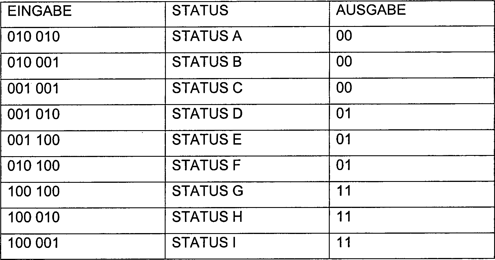
Der Metastatus und der Fehlerstatus werden basierend auf den aktuellen Eingabebannern und dem vorherigen Status zugeordnet.Of the Metastatus and error status are based on the current one Associated with input banners and the previous status.
Der Fehlerstatus ist ein Sonderfall, der die Ausgabebanner neu einstellt, wenn der Übergang von einem Status zum anderen keine für schwierige Straßenlagen erwartete logische Progression darstellt. Der Fehlerstatus hat die Form:Of the Error status is a special case that sets the output banners again, when the transition from one status to another, not for difficult road conditions expected logical progression represents. The error status has the Shape:

Wenn z. B. das TDIFF-Signal von einem STATUS A, STATUS B oder STATUS F einen STATUS G zuordnet und das TDIFF-Signal zu keinem Zeitpunkt während der vorherigen 25 Muster einem STATUS C, STATUS D oder STATUS E zugeordnet hat, ordnet das Statusgerät es dem Fehlerstatus zu und bleibt im Fehlerstatus, bis das TDIFF-Signal im STATUS A 20 Muster lang stabil geblieben ist.If z. Eg the TDIFF signal from a STATUS A, STATUS B or STATUS F assigns a STATUS G and the TDIFF signal at no time while the previous 25 patterns have a STATUS C, STATUS D or STATUS E the status device assigns it to the error status and remains in error status until the TDIFF signal in STATUS A 20 pattern has remained stable for a long time.
Der Metastatus ist ein instabiler STATUS A. Zum Nachvollziehen, wie viele aufeinander folgende Male ein STATUS A auftritt, wird ein Zähler verwendet. Wenn der Metastatus eine eingestellte Grenze überschreitet, werden die Ausgabebanner BANNER6 und BANNER7 wieder eingestellt. Solange der Metastatus-Zähler sich unterhalb der eingestellten Grenze befindet, wird das Ausgabebanner unverändert sein. Wenn also ein STATUS F einem STATUS A vorausgeht, wird das Ausgabebanner 01 sein, solange der Wert des Metastatuszählers sich unterhalb der eingestellten Grenze befindet.Of the Metastatus is an unstable STATUS A. To understand how many consecutive times a STATUS A occurs will be counter used. If the metastatus exceeds a set limit, then the output banners BANNER6 and BANNER7 are set again. So long the metastatus counter is below the set limit, the output banner becomes unchanged be. So if a STATUS F precedes a STATUS A, it will Output banner 01 as long as the value of the meta-status counter is up is below the set limit.
Zur besseren Aufbewahrung der Aufzeichnungen des bisherigen Verhaltens mit minimalen Speicheranforderungen wird eine sekundäre Funktion in das primäre Statusgerät integriert. Die sekundäre Funktion besteht aus zwei Bannern und einem Zähler. Das erste Banner ist ein TIEFSTPUNKTBANNER. Dieses Banner wird eingestellt, wenn das Statusgerät in einem STATUS C, D oder E verbleibt. Das zweite Banner ist ein SPITZENBANNER. Dieses Banner wird eingestellt, wenn das Statusgerät in einem STATUS G, H oder I verbleibt und das TIEFSTPUNKTBANNER bereits eingestellt worden ist. Wenn ein Banner eingestellt wird, wird das andere Banner gelöscht. Wenn das Statusgerät über eine eingestellte Anzahl von Mustern (50 Muster auf den H-Wagen, 15 auf dem CK-LKW) in einem STATUS A, B oder F verbleibt, werden sowohl das SPITZENBANNER als auch das TIEFSTPUNKTBANNER gelöscht. Das impliziert, dass ein bestimmtes System innerhalb einer eingestellten Anzahl von Mustern zwischen Durchgängen und Spitzen übergehen sollte, um als ein schwieriges Straßenlagensignal eingestuft zu werden. Der Zähler ist ein als TECOUNT bezeichneter Übergangs-Ereigniszähler. Das SPITZENBANNER wird nur eingestellt, wenn das TDIFF-Signal innerhalb eines maximalen Sets von Mustern von einer TIEFSTPUNKT-Bedingung zu einer SPITZEN-Bedingung übergegangen ist. Wenn das SPITZENBANNER eingestellt ist und der Frequenzzeitgeber für schwierige Straßenlagen sich innerhalb des gültigen Bereichs befindet, dann wird ein Kompensationswert berechnet und im AUSGLEICH SCHWIERIGE STRAßENLAGE gespeichert.to better storage of records of past behavior with minimal memory requirements becomes a secondary function in the primary state machine integrated. The secondary Function consists of two banners and a counter. The first banner is a DEEP POINT BANNER. This banner will be discontinued if that state machine remains in a STATUS C, D or E. The second banner is on PEAK FLAG. This banner is set when the status device is in one STATUS G, H or I remains and the DEFLECTIVE BANNER is already set has been. If one banner is set, the other banner becomes deleted. If the status device has a set number of patterns (50 patterns on H-cars, 15 on the CK truck) remains in a STATUS A, B or F, both the TOP BANNER as well as the DEEP BANNER are deleted. The implies that a particular system is set within a system Pass number of patterns between passes and peaks should be classified as a difficult road signal become. The counter is a transition event counter called TECOUNT. The TOP BANNER is set only when the TDIFF signal is within of a maximum set of patterns from a DEPTH condition passed to a TOP condition is. When the TOP BANNER is set and the frequency timer for difficult ones Roads themselves within the valid Range, then a compensation value is calculated and COMPARED WITH DIFFICULT ROAD SITUATION saved.
Die Interaktion zwischen dem Statusgerät, dem TIEFSTPUNKT- und dem SPITZENBANNER und dem TECOUNT wird in der folgenden Tabelle beschrieben:The Interaction between the status device, the DEEP POINT and the TOP BANNER and the TECOUNT is described in the following table:

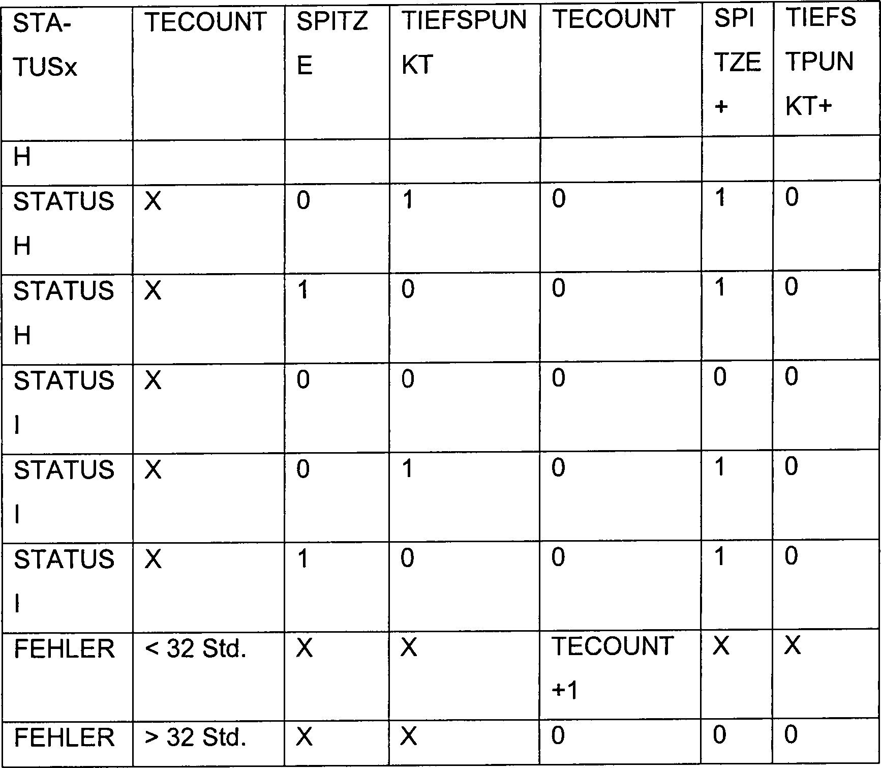
Die sekundäre Funktion impliziert, dass einem Spitzenereignis immer ein Tiefstpunktereignis vorangehen muss und zusätzlich ein Tiefspunktereignis innerhalb einer begrenzten Anzahl von Mustern immer in ein Spitzenereignis übergehen soll.The secondary Function implies that a peak event is always a trough event must go ahead and in addition a low point event within a limited number of patterns always turn into a top event should.
Nachdem das Statusgerät in die nächste Phase übergegangen ist, wird der Zeitgeber schwierige Straßenlage getestet, um festzustellen, ob er sich innerhalb eines gültigen Bereichs befindet. Im Idealfall sollte die vom STATUS D bis zum STATUS H abgelaufene Zeit das Eineinhalbfache der grundlegenden Frequenz der Fahrzeugaufhängung sein (wobei T = 1/f).After this the status device in the next Phase passed is the timer is tested roadside difficult to determine whether he is within a valid Area is located. Ideally, it should be from STATUS D to STATUS H elapsed time one and a half times the basic Frequency of vehicle suspension be (where T = 1 / f).
Das Statusgerät hat zwei Hauptausgabebanner. Das erste Hauptausgabebanner lässt einen Zeitgeber schwierige Straßenlage zu. Dieser Zeitgeber wird der zur Messung der Periode des Beschleunigungssignals genutzt. Die grundlegende Frequenz des TDIFF-Signals muss nahe des Frequenzbereichs der Aufhängung sein (in den meisten Automobilen rund 12 Hz), um eine Bedingung zur Zulassung des Ausgleichs schwierige Straßenlage zu erfüllen. Das zweite Ausgabebanner ist das Banner AUSGLEICH ZULASSEN. Die Ausgleichsfunktion schwierige Straßenlage sollte nur einen Ausgleich berechnen, wenn der aktuelle Status des Statusgeräts G, H oder I ist.The state machine has two main output banners. The first main issue banner leaves one Timer difficult roadholding to. This timer is used to measure the period of the acceleration signal. The basic frequency of the TDIFF signal must be close to the frequency range be the suspension (in most automobiles around 12 Hz) to a condition for approval of balancing difficult roadholding to fulfill. The second output banner is the ADD COMPENSATION banner. The Compensation function difficult roadholding should only compensate calculate when the current state of the status device G, H or I is.
Ein
Ausgleich schwierige Straßenlage
wird folgendermaßen
berechnet:
WENN:
der Zeitgeber schwierige Straßenlage
sich innerhalb eines gültigen
Bereichs befindet
UND
das Banner AUSGLEICH ZULASSEN eingestellt
ist
UND
das Banner SPITZE eingestellt ist
UND
die
Anfahr-Übergangs-Reaktion
erloschen ist.A compensation of difficult road conditions is calculated as follows:
IF:
the timer is difficult to track within a valid range
AND
The ADJUST BALANCE banner is set
AND
the banner TOP is set
AND
the start-transition reaction has gone out.
Wenn
alle diese Bedingungen zutreffen, dann besteht die letzte Stufe
in der Berechnung eines Ausgleichs. Die Ausgleichsgleichung hat
die folgende Form:
TDIFF(n)·5/8 = IRROS mit einem als
Wn·(TRES(n – 128)·1/9 +
OS-GRENZE/2) definierten
Sättigungswert.If all of these conditions are true, then the last step is to calculate a compensation. The equalization equation has the following form:
TDIFF (n) * 5/8 = IRROS with a saturation value defined as Wn * (TRES (n-128) * 1/9 + OS LIMIT / 2).
Wobei Sn einen Dämpfungskoeffizienten proportional zur Steifheit der Fahrzeugaufhängung darstellt. Ein Lieferwagen zum Beispiel könnte einen Dämpfungskoeffizienten von 1,5 einsetzen, eine Luxuslimousine kann jedoch lediglich einen Dämpfungskoeffizienten von 0,5 benötigen. Eine Sättigungsgrenze stellt eine realistische obere Grenze in der Größenordnung der auszugleichenden Störungen bei schwieriger Straßenlage dar.In which Sn a damping coefficient proportional to the stiffness of the vehicle suspension. A delivery van for example a damping coefficient 1.5, but a luxury sedan can only have one damping coefficient of 0.5 need. A saturation limit represents a realistic upper limit on the order of magnitude to be compensated disorders in difficult road conditions.
In der Praxis sollte eine Beschleunigung von mehr als 1,5 g als extrem betrachtet werden.In In practice, an acceleration of more than 1.5 g should be considered extreme to be viewed as.
Stufenausgleichstep counterbalance
Die Stufenfunktion wird zum Ausgleich für erwartete große Abweichungen im TDIFF-Signal verwendet. Obwohl es zwei unterschiedliche Typen von Stufenfunktionen gibt, werden beide im Kontrollprogramm unter derselben Ausgleichsvariablen eingeordnet.The Step function compensates for expected large deviations used in the TDIFF signal. Although there are two different types of step functions, both are subset in the control program same equalization variables.
Die
erste Stufenfunktion basiert auf Zeit und wird auf der linken Seite
der in
Einige
Systeme, wie das, das, das auf der linken Seite auf der Grafik in
- 1. Die TDIFF-Daten werden überprüft und der Wert der zweiten positiven Spitze aufgezeichnet. Die Zeit vom Start bis zum dritten, vierten oder fünften „Buckel" wird aufgezeichnet, wenn gesagt werden kann, dass dort eine Übergangsreaktion erloschen ist.
- 2. Diese Werte werden in eine Übersichtstafel aufgenommen.
- 1. The TDIFF data is checked and the value of the second positive peak recorded. The time from the start to the third, fourth or fifth "hump" is recorded when it can be said that a transient response has gone out there.
- 2. These values are included in a summary table.
Eine
Funktion wird basierend auf der Größenordnung der zweiten positiven
Spitze als eine Voltfunktion mit der folgenden Formel generiert:
α × IVOLTUS
+ b. Das ist die zur Berechnung des Wertes der schwach gedämpften Stufenreaktion
verwendete Gleichung.A function is generated based on the magnitude of the second positive peak as a volt function with the following formula:
α × IVOLTUS + b. This is the equation used to calculate the value of the weakly damped step reaction.
Die
Dauer des Übergangs
kann entweder eine Konstante sein (nur, wenn für Größenreduktionen erforderlich)
oder eine Gleichung mit der Form
α × IVOLTUS + b, wobei „b" die Mindestabfallzeit
für die Übergangsreaktion
ist und „a" die Änderungsbedingung
des Voltzahlausgleichs ist, die der maximalen Abfallzeit für die Übergangsreaktion
entspricht. Alle Zeiten werden in MODECT gemessen, das eine Auflösung von
4 ms hat. Z. B.:
WENN
die Mindestabfallzeit = 90 ms
DANN
ist
der MODECT-Wert 90/4 = 22.
WENN
die maximale Abfallzeit
= 120 ms
DANN
ist der MODECT-Wert 120/4 = 30The duration of the transition can either be a constant (only if required for size reductions) or an equation with the shape
α × IVOLTUS + b, where "b" is the minimum fall time for the transient response and "a" is the change condition of the voltage equalization that corresponds to the maximum fall time for the transient response. All times are measured in MODECT, which has a resolution of 4 ms. For example:
IF
the minimum decay time = 90 ms
THEN
is the MODECT value 90/4 = 22.
IF
the maximum fall time = 120 ms
THEN
is the MODECT value 120/4 = 30
Der zweite Typ der Stufenfunktion berücksichtigt Unregelmäßigkeiten in der Gummidichtung am Ende der Fahrt. Es gibt mehrere Türflügelsysteme, wie z. B. Fahrzeugtürsystemkonzepte, bei denen eine Kante des Glases Kontakt mit der Gummidichtung hat, während es zwischen einer anderen Kante des Glases und der Gummidichtung eine erhebliche Öffnung (+ 6 mm) gibt. Die Stufenfunktion der zweiten Position berücksichtigt die Störungen im TDIFF-Signal, während die Zulassung des Anti-Einklemmsystems aktiv bleibt.Of the second type of step function takes into account irregularities in the rubber seal at the end of the ride. There are several door leaf systems, such as B. vehicle door system concepts, where an edge of the glass makes contact with the rubber seal, while it between another edge of the glass and the rubber seal a significant opening (+ 6 mm). The step function of the second position takes into account the disorders in the TDIFF signal while the approval of the anti-pinching system remains active.
Die
Stufenfunktion des zweiten Endbereichs wird als eine Positionsfunktion
zugelassen, wie am Ende der Grafik in
- 1. Aufzeichnen der Positionszählung, in der TDIFF ansteigt,
- 2. Aufzeichnen der Spitzengröße von TDIFF in diesem letzten Bereich der Bahn.
- 3. Aufbau einer Ansichtstafel dieser Werte über die Voltzahl und die Temperatur und
- 4. Erstellung einer Funktion basierend auf der Temperatur und der Voltzahl, die diesem Anstieg des TDIFF zuzuordnen sind.
- 1. Record the position count in which TDIFF increases,
- 2. Record the peak size of TDIFF in this last area of the track.
- 3. Construction of a view table of these values on the voltage and the temperature and
- 4. Create a function based on the temperature and voltage associated with this increase in TDIFF.
Diese Funktion wird zur für die Größenordnung von ISTEPOS zu implementierenden auf der Position basierenden Gleichung.These Function becomes for the order of magnitude ISTEPOS to implement the position-based equation.
Geschwindigkeitsausgleich (RPM)speed compensation (RPM)
Der
Geschwindigkeitsausgleich wird zum Ersatz des Voltzahlausgleichs
während
des Dauerzustands-Betriebs des Motors
Einige
unabhängige
Faktoren, wie z. B. ein nicht korrekt gekoppelter oder angebrachter
Motor in einem System oder ein Widerstand des Kabelbaums, der sich
von dem für
die Charakterisierung genutzten Wert erheblich unterscheidet, oder
ein Regulator mit einer hohen Effizienztoleranz, können die
Geschwindigkeitskompensation behindern. Die Überwachung der Geschwindigkeit
der Rotation der Armatur
Die
zur Implementierung der Geschwindigkeitskompensation verwendete
Kontrollsequenz wird in
Unter
Bezugnahme auf die Blockdiagramme in den
Die
Haupt- oder Kontrollsequenz
Ab
der Abfragestufe
Als
Nächstes
fragt die Kontrolle
Als
Nächstes
führt die
Kontrolle
Während des
Hauptprogramms wird Stufe
Schließlich tritt
Stufe
Als
Nächstes,
in Stufe
Als
Nächstes,
in Stufe
Schließlich, in
Stufe
Multi-Zonen-AusgleichMulti-zone compensation
Die vorliegende Erfindung behandelt ebenfalls ein System zur Feststellung von Hindernissen mit einer Vielzahl von unterschiedlichen Betriebsbereichen, in dem ein Türflügel, wie z. B. ein Fahrzeug-Sonnendach, ein Schiebefenster, eine Schiebetür, usw. zwei unterschiedliche Bewegungsmodi zwischen zwei Positionen in Betrieb hat, die aufgrund von unterschiedlichen Betriebsparametern oder umgebungsbedingten Bedingungen in jedem Bereich in multiple Bereiche unterteilt werden können, wie z. B. ein Gleitglastürflügel, der aufgrund eines Hebelarms im Mechanismus in einem Bereich gegenüber dem Gleiten in einem Kanal im Mechanismus eines anderen Bereichs schwenkt.The The present invention also deals with a system for detection obstacles with a variety of different operating areas, in which a door leaf, like z. As a vehicle sunroof, a sliding window, a sliding door, etc. Two different modes of movement between two positions in operation has, due to different operating parameters or environmental conditions in each area into multiple areas can be divided such as B. a Gleitglastürflügel, the due to a lever arm in the mechanism in an area opposite to the Sliding in one channel in the mechanism of another area pans.
In
Da
die Geschwindigkeitsabweichungen unterschiedlich sind, wenn sich
der Türflügel
Zum
Beispiel kann die Niveau-Größenordnung
des Geräuschs
oder des Ausgleichs
Auf ähnliche
Weise können
die oben beschriebenen und in
Darüber hinaus kann jede oder können alle Kompensationsfaktoren, wie z. B. schwierige Straßenlage, Voltzahl, Temperatur, usw. unterschiedliche Ansichtstafel-Werte haben oder in jedem Bereich unterschiedliche Algorithmen einsetzen.Furthermore anyone can or can all compensation factors, such as B. difficult road holding, voltage, Temperature, etc. have different view panel values or use different algorithms in each area.
Zusammenfassend wurden ein einzigartiges Kontrollgerät der Anti-Einklemmfunktion basierend auf der Motorengeschwindigkeit und ein Verfahren mit einer soliden Kontrolle offen gelegt, das sich an multiple Bewegungsmodi des Türflügels anpasst, Kompensationen für verschiedene Ereignisse beinhaltet, unter Einschluss der Einkaufsbedingung, der Voltzahl, der Raumtemperatur, schwieriger Straßenlagen, dem Ende der Bereichsrampe, des Anfahr-Übergangs, des Ausgleichs basierend auf der Zeit oder der Position.In summary became a unique controller of anti-pinch function based on engine speed and a method with a solid control disclosed that Adapts to multiple modes of movement of the door leaf, compensations for different Events includes, including the purchase condition, the Voltage, room temperature, difficult road conditions, the end of the range ramp, the start-up transition, compensation based on time or position.
Claims (14)
Applications Claiming Priority (3)
| Application Number | Priority Date | Filing Date | Title |
|---|---|---|---|
| US10/159,186 US6678601B2 (en) | 2002-05-31 | 2002-05-31 | Motor speed-based anti-pinch control apparatus and method with rough road condition detection and compensation |
| US159186 | 2002-05-31 | ||
| PCT/US2003/016930 WO2003102338A2 (en) | 2002-05-31 | 2003-05-30 | Motor speed-based anti-pinch control apparatus and method with rough road condition detection and compensation |
Publications (2)
| Publication Number | Publication Date |
|---|---|
| DE60303668D1 DE60303668D1 (en) | 2006-04-27 |
| DE60303668T2 true DE60303668T2 (en) | 2006-10-05 |
Family
ID=29582839
Family Applications (1)
| Application Number | Title | Priority Date | Filing Date |
|---|---|---|---|
| DE60303668T Expired - Lifetime DE60303668T2 (en) | 2002-05-31 | 2003-05-30 | DEVICE FOR CONTROLLING ENGINE SPEED-BASED COVER PROTECTION AND METHOD FOR DETECTING AND COMPENSATING BAD TRAFFIC CONDITIONS |
Country Status (5)
| Country | Link |
|---|---|
| US (1) | US6678601B2 (en) |
| EP (1) | EP1509824B1 (en) |
| AT (1) | ATE318419T1 (en) |
| DE (1) | DE60303668T2 (en) |
| WO (1) | WO2003102338A2 (en) |
Cited By (1)
| Publication number | Priority date | Publication date | Assignee | Title |
|---|---|---|---|---|
| DE102007030656A1 (en) * | 2007-07-02 | 2009-01-08 | Brose Fahrzeugteile Gmbh & Co. Kommanditgesellschaft, Hallstadt | Method for detecting a trapping case and adjusting device |
Families Citing this family (30)
| Publication number | Priority date | Publication date | Assignee | Title |
|---|---|---|---|---|
| US7190145B2 (en) * | 2002-01-16 | 2007-03-13 | Ballard Power Systems Corporation | Method and apparatus for improving speed measurement quality in multi-pole machines |
| US6822410B2 (en) * | 2002-05-31 | 2004-11-23 | Valeo Electrical Systems, Inc. | Motor speed-based anti-pinch control apparatus and method |
| DE202004000266U1 (en) * | 2004-01-10 | 2005-02-24 | Brose Fahrzeugteile Gmbh & Co. Kommanditgesellschaft, Coburg | Control device of an adjusting device of a motor vehicle, in particular of a motor vehicle window lifter |
| US7520567B2 (en) * | 2004-09-23 | 2009-04-21 | Crown Equipment Corporation | Systems and methods for seat repositioning |
| US7121608B2 (en) * | 2004-09-23 | 2006-10-17 | Crown Equipment Corporation | Rotating and/or swiveling seat |
| US7059680B2 (en) | 2004-09-23 | 2006-06-13 | Crown Equipment Corporation | Seat repositioning device with release on control handle |
| DE102005005185B4 (en) * | 2005-02-03 | 2007-04-12 | Daimlerchrysler Ag | Switching arrangement for a switching element for opening and closing a vehicle wing |
| US7576502B2 (en) * | 2005-07-28 | 2009-08-18 | Arvinmeritor Light Vehicle Systems - France | Method and apparatus for closing a powered closure of a vehicle |
| JP4103906B2 (en) * | 2005-08-23 | 2008-06-18 | オムロン株式会社 | Motor control device |
| JP4438733B2 (en) * | 2005-10-26 | 2010-03-24 | ソニー株式会社 | Electronic device and electronic device control method |
| US20070095595A1 (en) * | 2005-11-02 | 2007-05-03 | Arvinmeritor Light Vehicle Systems-France | Anti-squeeze method utilizing airbag information |
| DE102006006723A1 (en) * | 2006-02-13 | 2007-08-23 | Conti Temic Microelectronic Gmbh | Monitoring method for electrically operating adjustment drive in motor vehicle, involves supplying parameter by other control units existing in vehicle, where adjustment drive is assigned to control unit to evaluate parameters |
| US7591170B2 (en) * | 2007-01-23 | 2009-09-22 | Gm Global Technology Operations, Inc. | Rough road detection system |
| DE102007056228B4 (en) * | 2007-11-22 | 2010-04-22 | Continental Automotive Gmbh | Method and device for correcting temperature-dependent changes in the mechanical properties of a movable closing part of a vehicle |
| JP4944255B2 (en) * | 2008-01-16 | 2012-05-30 | テレフオンアクチーボラゲット エル エム エリクソン(パブル) | Method for detecting opening of cover sealing device and device |
| US8493081B2 (en) | 2009-12-08 | 2013-07-23 | Magna Closures Inc. | Wide activation angle pinch sensor section and sensor hook-on attachment principle |
| US9234979B2 (en) | 2009-12-08 | 2016-01-12 | Magna Closures Inc. | Wide activation angle pinch sensor section |
| FR2961967B1 (en) * | 2010-06-24 | 2012-07-20 | Continental Automotive France | METHOD FOR MANAGING THE POWER SUPPLY VOLTAGE OF AN AUTOMOTIVE VEHICLE ELECTRONIC COMPUTER |
| DE102010064213A1 (en) * | 2010-12-27 | 2012-06-28 | Robert Bosch Gmbh | Method and device for providing a movement indication, in particular for a blocking detection of a locking system |
| DE102011111450A1 (en) * | 2011-08-30 | 2013-02-28 | Brose Fahrzeugteile Gmbh & Co. Kommanditgesellschaft, Hallstadt | Method and device for monitoring a drive unit having a rotating drive motor, in particular a window lifter |
| US9080363B2 (en) * | 2012-03-13 | 2015-07-14 | Ford Global Technologies, Llc | Vehicle door swing governor |
| DE102012024902A1 (en) * | 2012-12-20 | 2014-06-26 | Brose Fahrzeugteile Gmbh & Co. Kommanditgesellschaft, Hallstadt | Adjustment device for adjusting a movable vehicle part and method for operating the same |
| CN105579322B (en) * | 2013-09-26 | 2017-11-14 | 纳博特斯克有限公司 | Opening and closing vehicle door control device |
| CN104514456B (en) * | 2013-09-27 | 2016-10-05 | 深圳市金证卡尔电子有限公司 | Window opening and closing control system and method |
| US10117797B2 (en) * | 2015-03-10 | 2018-11-06 | Pride Mobility Products Corporation | Lift chair control device |
| US10392849B2 (en) | 2017-01-18 | 2019-08-27 | Ford Global Technologies, Llc | Assembly and method to slow down and gently close door |
| US10161177B1 (en) * | 2017-10-20 | 2018-12-25 | Ford Global Technologies, Llc | Anti-pinch moonroof and associated method |
| CN110056280B (en) * | 2018-01-19 | 2021-08-06 | 南京天擎汽车电子有限公司 | Anti-pinch control method and anti-pinch control system |
| CN111367205B (en) * | 2020-03-05 | 2021-07-09 | 南京美均电子科技有限公司 | Anti-pinch algorithm for electric tail gate control |
| CN111877906A (en) * | 2020-07-03 | 2020-11-03 | 一汽奔腾轿车有限公司 | Anti-pinch control method for electric closing of automobile tail door |
Family Cites Families (52)
| Publication number | Priority date | Publication date | Assignee | Title |
|---|---|---|---|---|
| DE2926938A1 (en) | 1979-07-04 | 1981-01-22 | Rau Swf Autozubehoer | SWITCHING ARRANGEMENT FOR DRIVING A MOVABLE ELEMENT, ESPECIALLY FOR DRIVING DISCS OR THE LIKE. IN MOTOR VEHICLES |
| DE3346366C2 (en) | 1983-12-22 | 1985-12-05 | Helmut Hund KG, 6330 Wetzlar | Safety circuit for electric motor-driven window regulators for automobiles or similar vehicles |
| DE3532078A1 (en) | 1984-09-13 | 1986-04-17 | Aisin Seiki K.K., Kariya, Aichi | ENGINE CONTROL METHOD AND DEVICE THEREFOR |
| JPH0547255Y2 (en) | 1985-09-04 | 1993-12-13 | ||
| JPH07118925B2 (en) | 1987-09-29 | 1995-12-18 | アルプス電気株式会社 | Power window equipment |
| US5012168A (en) | 1990-02-20 | 1991-04-30 | Ford Motor Company | Method and apparatus for detecting stall current in an energized electric motor |
| US5218282A (en) | 1990-03-22 | 1993-06-08 | Stanley Home Automation | Automatic door operator including electronic travel detection |
| US5069000A (en) | 1990-03-22 | 1991-12-03 | Masco Industries, Inc. | Reversing apparatus for powered vehicle door systems |
| DE4020351A1 (en) * | 1990-06-27 | 1992-01-09 | Kostal Leopold Gmbh & Co Kg | Electronically monitoring and controlling window winder - using additional body motion sensor to avoid false triggering of unit in motor vehicle |
| US5334876A (en) | 1992-04-22 | 1994-08-02 | Nartron Corporation | Power window or panel controller |
| US5952801A (en) | 1992-04-22 | 1999-09-14 | Nartron Corporation | Power window or panel controller |
| US6064165A (en) | 1992-04-22 | 2000-05-16 | Nartron Corporation | Power window or panel controller |
| DE4214998C2 (en) | 1992-05-06 | 1995-06-29 | Prettl Rolf | Door drive and method for operating a door drive |
| US5278480A (en) | 1992-10-26 | 1994-01-11 | Stanley Home Automation | Door opener control with adaptive limits and method therefor |
| JPH06197592A (en) | 1992-12-25 | 1994-07-15 | Tokai Rika Co Ltd | Controlling device for drive of motor |
| JP3253031B2 (en) | 1993-01-21 | 2002-02-04 | 自動車電機工業株式会社 | Motor control method and device for power window device |
| DE4315637C2 (en) | 1993-05-11 | 1996-12-19 | Brose Fahrzeugteile | Method for recognizing the position and the direction of movement of a movably mounted part |
| DE4330904A1 (en) | 1993-09-11 | 1995-03-16 | Teves Gmbh Alfred | Safety device for moving parts |
| JP2891869B2 (en) | 1994-03-31 | 1999-05-17 | 株式会社大井製作所 | Opening / closing body drive control device |
| JP3182294B2 (en) | 1994-05-11 | 2001-07-03 | アスモ株式会社 | Moving object position detection device |
| JP3555180B2 (en) | 1994-06-24 | 2004-08-18 | 住友電装株式会社 | Anti-trapping device in automatic window opening / closing mechanism |
| US5497326A (en) | 1994-08-03 | 1996-03-05 | The Cherry Corporation | Intelligent commutation pulse detection system to control electric D.C. motors used with automobile accessories |
| JP3467875B2 (en) | 1994-12-13 | 2003-11-17 | 株式会社デンソー | Power window control device |
| DE4444762A1 (en) | 1994-12-19 | 1996-06-20 | Bosch Gmbh Robert | Circuit arrangement and method for operating an adjustment drive |
| DE19515322C2 (en) | 1995-04-20 | 1997-12-04 | Brose Fahrzeugteile | Drive device with an electric motor and a relay that switches the motor current |
| US5610484A (en) | 1995-05-04 | 1997-03-11 | Itt Automotive Electrical Systems, Inc. | Auto reverse power closure system |
| EP0751274A1 (en) | 1995-06-30 | 1997-01-02 | Siemens Aktiengesellschaft | Actuator |
| US5616997A (en) | 1995-10-10 | 1997-04-01 | Itt Automotive Electrical Systems, Inc. | Auto up window with obstacle detection system |
| DE19539578B4 (en) | 1995-10-25 | 2007-04-05 | Robert Bosch Gmbh | Method for monitoring the movement path of a part |
| DE19539577B4 (en) | 1995-10-25 | 2007-04-05 | Robert Bosch Gmbh | Method for monitoring the movement path of a part |
| US5585702A (en) | 1995-11-03 | 1996-12-17 | Itt Automotive Electrical Systems, Inc. | Auto up window with osbtacle detection system |
| US6194855B1 (en) | 1996-02-27 | 2001-02-27 | Robert Bosch Gmbh | Variable drive with protection against jamming for movable parts |
| DE19610626C2 (en) | 1996-03-19 | 2003-01-23 | Bosch Gmbh Robert | Follow-up detection of electric actuators |
| DE19611535A1 (en) | 1996-03-23 | 1997-09-25 | Bosch Gmbh Robert | Device and method for electronically monitoring an adjustment drive arranged in a vehicle |
| DE19618219B4 (en) | 1996-05-07 | 2004-04-29 | Robert Bosch Gmbh | Device for the electronic monitoring of an adjustment drive |
| DE19618853C1 (en) | 1996-05-10 | 1997-08-14 | Brose Fahrzeugteile | Motorised window drive with electronic anti-jamming protection e.g. for motor vehicles |
| DE19628203C2 (en) | 1996-07-12 | 2001-11-08 | Brose Fahrzeugteile | Method for limiting the excess force of an electrically controlled, power-operated unit when moving to its closed position, in particular when moving to the closed position of a window regulator of a motor vehicle |
| DE19804175A1 (en) * | 1997-02-04 | 1998-09-03 | Nissan Motor | Automatic door or window operating system with incorporated obstacle detection |
| DE19711979A1 (en) | 1997-03-12 | 1998-10-08 | Brose Fahrzeugteile | Process for electrical control and regulation of the movement of electrically operated units |
| DE19710338C5 (en) | 1997-03-13 | 2007-06-06 | Conti Temic Microelectronic Gmbh | Method for controlling the closing operation of closing devices with at least one electromotively moving part |
| DE19733581C1 (en) | 1997-08-02 | 1998-10-29 | Telefunken Microelectron | Identifying position-movement direction of movable part preset at electric motor |
| US6125583A (en) | 1997-08-13 | 2000-10-03 | Atoma International Inc. | Power sliding mini-van door |
| US5917296A (en) | 1997-11-21 | 1999-06-29 | Valeo Electrical Systems, Inc. | Optimum motor speed control system |
| JPH11324481A (en) | 1998-05-20 | 1999-11-26 | Denso Corp | Power window device having jamming prevention function |
| DE19916400C1 (en) * | 1998-07-24 | 2000-05-25 | Brose Fahrzeugteile | Method for regulating motor-driven adjustment devices in motor vehicles |
| JP4244412B2 (en) | 1998-09-30 | 2009-03-25 | アイシン精機株式会社 | Motor rotation pulse generation circuit for DC motor and pinching detection device using the circuit |
| DE19854038C2 (en) * | 1998-11-13 | 2003-09-04 | Brose Fahrzeugteile | Device for detecting the adjustment of translationally moved adjustment devices in vehicles |
| JP4120074B2 (en) | 1998-11-30 | 2008-07-16 | アイシン精機株式会社 | Automatic opening / closing body pinching prevention device |
| JP3730795B2 (en) | 1998-12-28 | 2006-01-05 | アルプス電気株式会社 | Power window device pinching detection method |
| US6051945A (en) * | 1999-01-25 | 2000-04-18 | Honda Giken Kogyo Kabushiki Kaisha | Anti-pinch safety system for vehicle closure device |
| US6308461B1 (en) | 1999-09-08 | 2001-10-30 | Meritor Light Vehicle Systems, Inc. | Method and system for detecting an object in the path of an automotive window utilizing a piezoelectric sensor |
| DE10042169B4 (en) * | 2000-08-15 | 2011-03-24 | Brose Fahrzeugteile Gmbh & Co. Kommanditgesellschaft, Coburg | Method for determining a maximum permissible engine torque |
-
2002
- 2002-05-31 US US10/159,186 patent/US6678601B2/en not_active Expired - Lifetime
-
2003
- 2003-05-30 AT AT03731443T patent/ATE318419T1/en not_active IP Right Cessation
- 2003-05-30 EP EP03731443A patent/EP1509824B1/en not_active Expired - Lifetime
- 2003-05-30 WO PCT/US2003/016930 patent/WO2003102338A2/en active IP Right Grant
- 2003-05-30 DE DE60303668T patent/DE60303668T2/en not_active Expired - Lifetime
Cited By (1)
| Publication number | Priority date | Publication date | Assignee | Title |
|---|---|---|---|---|
| DE102007030656A1 (en) * | 2007-07-02 | 2009-01-08 | Brose Fahrzeugteile Gmbh & Co. Kommanditgesellschaft, Hallstadt | Method for detecting a trapping case and adjusting device |
Also Published As
| Publication number | Publication date |
|---|---|
| US6678601B2 (en) | 2004-01-13 |
| WO2003102338A2 (en) | 2003-12-11 |
| ATE318419T1 (en) | 2006-03-15 |
| EP1509824B1 (en) | 2006-02-22 |
| WO2003102338A3 (en) | 2004-02-12 |
| EP1509824A2 (en) | 2005-03-02 |
| US20030225497A1 (en) | 2003-12-04 |
| DE60303668D1 (en) | 2006-04-27 |
Similar Documents
| Publication | Publication Date | Title |
|---|---|---|
| DE60303668T2 (en) | DEVICE FOR CONTROLLING ENGINE SPEED-BASED COVER PROTECTION AND METHOD FOR DETECTING AND COMPENSATING BAD TRAFFIC CONDITIONS | |
| US6794837B1 (en) | Motor speed-based anti-pinch control apparatus and method with start-up transient detection and compensation | |
| DE10051379B4 (en) | Safety device for a window lift | |
| US6822410B2 (en) | Motor speed-based anti-pinch control apparatus and method | |
| DE10145711B4 (en) | Opening and closing control device for a cover | |
| DE19511581C2 (en) | Drive control device for an opening / closing element | |
| DE69621344T2 (en) | SYSTEM FOR DETECTING AN OBSTACLE IN AUTOMATICALLY CLOSING WINDOWS | |
| EP1256154B1 (en) | Method of electronically monitoring and controlling a process for the adjustment of mobile parts | |
| EP1593805B1 (en) | Control unit and method for movement of a window pane of a convertible vehicle | |
| DE10297401T5 (en) | Capacitive multi-range pinch protection arrangement | |
| US6788016B2 (en) | Motor speed-based anti-pinch control apparatus and method with endzone ramp detection and compensation | |
| DE102014200819A1 (en) | Opening / closing body control unit | |
| DE202006008465U1 (en) | Control device and adjustment system of a motor vehicle | |
| EP1726076A1 (en) | Method for monitoring the adjustment movement of a component driven by a driving device | |
| WO2010124927A2 (en) | Method and device for detecting an entrapment situation | |
| DE102012011117A1 (en) | Adjusting system for vehicle, has evaluation and control unit which selects one threshold curve of several threshold curves stored in memory unit for comparing with current motion state in response to selection parameters | |
| WO2002023691A1 (en) | Method for making allowance for the vehicle attitude on operating closing piece systems on motor vehicles | |
| DE4330904A1 (en) | Safety device for moving parts | |
| DE102009028914A1 (en) | Method for recognizing trapping case of closing device, involves determining variable of state, which indicates force for movement of closing element in closing direction | |
| DE10011982A1 (en) | Electric motor for automobile windows or sun roof is current monitored to prevent trapping of foreign objects | |
| DE102016208946A1 (en) | Control device and method for detecting a movement impairment in a drive device | |
| DE10149578B4 (en) | Device and method for monitoring an adjustment of a motor vehicle, in particular a window regulator | |
| DE10041736C1 (en) | Device and method for detecting at least one parameter of a movement of parts which are movable relative to one another, in particular for adjusting drives in motor vehicles | |
| DE60118301T2 (en) | Method and system for determining the movement of an engine in a system for electric vehicle windows | |
| DE19619932A1 (en) | Electromotor drive, esp. for vehicle window |
Legal Events
| Date | Code | Title | Description |
|---|---|---|---|
| 8364 | No opposition during term of opposition |