DE102012024902A1 - Adjustment device for adjusting a movable vehicle part and method for operating the same - Google Patents
Adjustment device for adjusting a movable vehicle part and method for operating the same Download PDFInfo
- Publication number
- DE102012024902A1 DE102012024902A1 DE102012024902.0A DE102012024902A DE102012024902A1 DE 102012024902 A1 DE102012024902 A1 DE 102012024902A1 DE 102012024902 A DE102012024902 A DE 102012024902A DE 102012024902 A1 DE102012024902 A1 DE 102012024902A1
- Authority
- DE
- Germany
- Prior art keywords
- control unit
- servomotor
- vehicle part
- adjusting
- window
- Prior art date
- Legal status (The legal status is an assumption and is not a legal conclusion. Google has not performed a legal analysis and makes no representation as to the accuracy of the status listed.)
- Withdrawn
Links
- 238000000034 method Methods 0.000 title claims description 23
- 230000002596 correlated effect Effects 0.000 claims abstract description 5
- 238000012937 correction Methods 0.000 claims description 17
- 230000007246 mechanism Effects 0.000 claims description 10
- 230000001419 dependent effect Effects 0.000 claims description 7
- 238000004590 computer program Methods 0.000 claims description 5
- 230000000875 corresponding effect Effects 0.000 claims description 5
- 230000001276 controlling effect Effects 0.000 claims description 4
- 230000008878 coupling Effects 0.000 claims description 2
- 238000010168 coupling process Methods 0.000 claims description 2
- 238000005859 coupling reaction Methods 0.000 claims description 2
- 241001074085 Scophthalmus aquosus Species 0.000 description 17
- 238000009529 body temperature measurement Methods 0.000 description 4
- 238000010586 diagram Methods 0.000 description 3
- 238000011161 development Methods 0.000 description 2
- 230000018109 developmental process Effects 0.000 description 2
- 238000005259 measurement Methods 0.000 description 2
- 230000008901 benefit Effects 0.000 description 1
- 210000001520 comb Anatomy 0.000 description 1
- 230000007423 decrease Effects 0.000 description 1
- 239000005357 flat glass Substances 0.000 description 1
- 238000009533 lab test Methods 0.000 description 1
- 238000007620 mathematical function Methods 0.000 description 1
- 230000005405 multipole Effects 0.000 description 1
- 238000010606 normalization Methods 0.000 description 1
- 230000008569 process Effects 0.000 description 1
- 239000007787 solid Substances 0.000 description 1
- 238000012360 testing method Methods 0.000 description 1
- 230000036962 time dependent Effects 0.000 description 1
Images
Classifications
-
- G—PHYSICS
- G05—CONTROLLING; REGULATING
- G05D—SYSTEMS FOR CONTROLLING OR REGULATING NON-ELECTRIC VARIABLES
- G05D3/00—Control of position or direction
-
- B—PERFORMING OPERATIONS; TRANSPORTING
- B60—VEHICLES IN GENERAL
- B60J—WINDOWS, WINDSCREENS, NON-FIXED ROOFS, DOORS, OR SIMILAR DEVICES FOR VEHICLES; REMOVABLE EXTERNAL PROTECTIVE COVERINGS SPECIALLY ADAPTED FOR VEHICLES
- B60J1/00—Windows; Windscreens; Accessories therefor
- B60J1/08—Windows; Windscreens; Accessories therefor arranged at vehicle sides
- B60J1/12—Windows; Windscreens; Accessories therefor arranged at vehicle sides adjustable
- B60J1/16—Windows; Windscreens; Accessories therefor arranged at vehicle sides adjustable slidable
- B60J1/17—Windows; Windscreens; Accessories therefor arranged at vehicle sides adjustable slidable vertically
-
- E—FIXED CONSTRUCTIONS
- E05—LOCKS; KEYS; WINDOW OR DOOR FITTINGS; SAFES
- E05F—DEVICES FOR MOVING WINGS INTO OPEN OR CLOSED POSITION; CHECKS FOR WINGS; WING FITTINGS NOT OTHERWISE PROVIDED FOR, CONCERNED WITH THE FUNCTIONING OF THE WING
- E05F15/00—Power-operated mechanisms for wings
- E05F15/60—Power-operated mechanisms for wings using electrical actuators
- E05F15/603—Power-operated mechanisms for wings using electrical actuators using rotary electromotors
- E05F15/665—Power-operated mechanisms for wings using electrical actuators using rotary electromotors for vertically-sliding wings
- E05F15/689—Power-operated mechanisms for wings using electrical actuators using rotary electromotors for vertically-sliding wings specially adapted for vehicle windows
- E05F15/695—Control circuits therefor
-
- E—FIXED CONSTRUCTIONS
- E05—LOCKS; KEYS; WINDOW OR DOOR FITTINGS; SAFES
- E05Y—INDEXING SCHEME ASSOCIATED WITH SUBCLASSES E05D AND E05F, RELATING TO CONSTRUCTION ELEMENTS, ELECTRIC CONTROL, POWER SUPPLY, POWER SIGNAL OR TRANSMISSION, USER INTERFACES, MOUNTING OR COUPLING, DETAILS, ACCESSORIES, AUXILIARY OPERATIONS NOT OTHERWISE PROVIDED FOR, APPLICATION THEREOF
- E05Y2400/00—Electronic control; Electrical power; Power supply; Power or signal transmission; User interfaces
- E05Y2400/10—Electronic control
- E05Y2400/32—Position control, detection or monitoring
- E05Y2400/334—Position control, detection or monitoring by using pulse generators
- E05Y2400/34—Pulse count limit setting
-
- E—FIXED CONSTRUCTIONS
- E05—LOCKS; KEYS; WINDOW OR DOOR FITTINGS; SAFES
- E05Y—INDEXING SCHEME ASSOCIATED WITH SUBCLASSES E05D AND E05F, RELATING TO CONSTRUCTION ELEMENTS, ELECTRIC CONTROL, POWER SUPPLY, POWER SIGNAL OR TRANSMISSION, USER INTERFACES, MOUNTING OR COUPLING, DETAILS, ACCESSORIES, AUXILIARY OPERATIONS NOT OTHERWISE PROVIDED FOR, APPLICATION THEREOF
- E05Y2400/00—Electronic control; Electrical power; Power supply; Power or signal transmission; User interfaces
- E05Y2400/10—Electronic control
- E05Y2400/32—Position control, detection or monitoring
- E05Y2400/35—Position control, detection or monitoring related to specific positions
- E05Y2400/354—End positions
-
- E—FIXED CONSTRUCTIONS
- E05—LOCKS; KEYS; WINDOW OR DOOR FITTINGS; SAFES
- E05Y—INDEXING SCHEME ASSOCIATED WITH SUBCLASSES E05D AND E05F, RELATING TO CONSTRUCTION ELEMENTS, ELECTRIC CONTROL, POWER SUPPLY, POWER SIGNAL OR TRANSMISSION, USER INTERFACES, MOUNTING OR COUPLING, DETAILS, ACCESSORIES, AUXILIARY OPERATIONS NOT OTHERWISE PROVIDED FOR, APPLICATION THEREOF
- E05Y2900/00—Application of doors, windows, wings or fittings thereof
- E05Y2900/50—Application of doors, windows, wings or fittings thereof for vehicles
- E05Y2900/53—Type of wing
- E05Y2900/55—Windows
Landscapes
- Engineering & Computer Science (AREA)
- Physics & Mathematics (AREA)
- General Physics & Mathematics (AREA)
- Automation & Control Theory (AREA)
- Mechanical Engineering (AREA)
- Power-Operated Mechanisms For Wings (AREA)
- Window Of Vehicle (AREA)
- Control Of Position Or Direction (AREA)
Abstract
Um eine Zielposition (xZ) eines bewegliches Fahrzeugteil (2) mittels einer motorischen Stellvorrichtung (1) mit einfachen Mitteln präzise anfahren zu können, wird ein Stellmotor (3) der Stellvorrichtung (1) um einen vorgegebenen Vorlauf (xV) vor dem Erreichen der Zielposition (xZ) gestoppt. Der Vorlauf (xV) wird dabei in Abhängigkeit der Motordrehzahl (n) oder einer damit korrelierten Stellgeschwindigkeitsmessgröße sowie in Abhängigkeit einer für die Umgebungstemperatur der Stellvorrichtung (1) charakteristischen Temperaturmessgröße (T) variiert.In order to be able to precisely move to a target position (xZ) of a movable vehicle part (2) by means of a motorized actuating device (1) using simple means, a servomotor (3) of the actuating device (1) is moved by a predetermined advance (xV) before the target position is reached (xZ) stopped. The advance (xV) is varied depending on the engine speed (n) or a correlated actuating speed measured variable and depending on a temperature measured variable (T) which is characteristic of the ambient temperature of the actuating device (1).
Description
Die Erfindung bezieht sich auf ein Verfahren zum Betrieb einer motorischen Stellvorrichtung für ein bewegliches Fahrzeugteil. Die Erfindung bezieht sich des Weiteren auf eine zugehörige Stellvorrichtung zur Verstellung des Fahrzeugteils. Bei dem zu verstellenden Fahrzeugteil handelt es sich insbesondere um eine Fahrzeug-Fensterscheibe, bei der Stellvorrichtung insbesondere um einen elektromotorischen Fensterheber.The invention relates to a method for operating a motor-driven positioning device for a movable vehicle part. The invention further relates to an associated adjusting device for adjusting the vehicle part. The vehicle part to be adjusted is, in particular, a vehicle window pane, in particular the adjusting device is an electromotive window regulator.
Eine präzise Einstellung der Stellposition ist bei einem motorisch beweglichen Fahrzeugteil oft erforderlich oder zumindest wünschenswert. So ist eine ungenaue Positionierung einer Fahrzeug-Fensterscheibe beispielsweise für die sogenannte Kurzhubfunktion von erheblichem Nachteil, bei der die Fensterscheibe aus der oberen Türdichtung einer rahmenlosen Fahrzeugtür herausgefahren wird, um eine widerstandsfreie Öffnung der Fahrzeugtür zu ermöglichen. Für die Kurzhubbewegung werden seitens der Fahrzeughersteller oft enge Grenzen gesetzt. Hierdurch soll sichergestellt werden, dass einerseits die Fensterscheibe vollständig aus der Fensterdichtung herausgefahren wird, dass aber andererseits die Fensterscheibe nach dem Kurzhub nicht zu weit offen steht, zumal ansonsten nach den geltenden gesetzlichen Vorschriften für das Rückfahren der Fensterscheibe mitunter zusätzliche Sicherheitsvorkehrungen wie z. B. eine Einklemmschutzautomatik benötigt werden.A precise adjustment of the parking position is often required or at least desirable in a motor vehicle movable part. Thus, an inaccurate positioning of a vehicle window pane, for example, for the so-called short-stroke function of considerable disadvantage in which the window is moved out of the upper door seal a frameless vehicle door to allow a resistance-free opening of the vehicle door. For the short-stroke movement, vehicle manufacturers often set narrow limits. This is to ensure that on the one hand, the window is completely moved out of the window seal, but on the other hand, the window after the short stroke is not too wide open, especially since otherwise according to the applicable legislation for the return of the window sometimes additional safety precautions such. B. an anti-trap automatic are needed.
Eine präzise Anfahrung ist aber auch bei anderen Stellpositionen einer Fensterscheibe wünschenswert, insbesondere beim Anfahren des unteren oder oberen Vorabschaltpunktes, an dem die Fensterscheibe üblicherweise gestoppt wird, kurz bevor sie den (unteren bzw. oberen) Blockzustand tatsächlich erreicht. Eine präzise Positionierung einer Fensterscheibe ist des Weiteren z. B. auch bei der Anfahrung des sogenannten RELAN(Relax After Normalization)-Punktes wünschenswert. Als RELAN-Punkt wird diejenige Fensterscheibenposition bezeichnet, zu der die Fensterscheibe häufig nach einer Justierungsfahrt in den unteren oder oberen Blockzustand zur Entspannung der Stellmechanik zurückgefahren wird.But a precise experience is also desirable in other positions of a window, especially when approaching the lower or upper Vorschaltschaltpunktes at which the window is usually stopped shortly before it actually reaches the (lower or upper) block state. A precise positioning of a window is further z. B. also desirable in the experience of the so-called RELAN (Relax After Normalization) point. As RELAN point that window pane position is referred to, to which the window pane is often moved back to an adjustment drive in the lower or upper block state to relax the actuating mechanism.
Eine präzise Einstellung der Stellposition ist ferner auch bei anderen speziellen Scheibenpositionen (z. B. einem automatisch eingestellten „Raucherspalt”) aus ästhetischen Gründen wünschenswert. Zudem ist eine präzise Stellpositionseinstellung auch bei anderen Stellvorrichtungen in einem Fahrzeug, insbesondere Sitzverstellungen, Tür- und Verdeckverstellungen, etc. von Vorteil.Precise setting of the setting position is also desirable for other specific slice positions (eg, an automatically adjusted "smoker gap") for aesthetic reasons. In addition, a precise adjustment of the parking position is also advantageous in the case of other adjusting devices in a vehicle, in particular seat adjustments, door and folding-top adjustments, etc.
Der Erfindung liegt die Aufgabe zugrunde, bei einer Stellvorrichtung der vorstehend genannten Art mit einfachen Mitteln eine besonders präzise Einstellung der Stellposition des zu verstellenden Fahrzeugteils sicherzustellen.The invention has for its object to ensure in a control device of the aforementioned type with simple means a particularly precise adjustment of the parking position of the vehicle part to be adjusted.
Hinsichtlich eines Verfahrens zum Betrieb einer motorischen Stellvorrichtung für ein bewegliches Fahrzeugteil wird die Aufgabe erfindungsgemäß gelöst durch die Merkmale des Anspruchs 1. Hinsichtlich der Stellvorrichtung wird die Aufgabe erfindungsgemäß gelöst durch die Merkmale des Anspruchs 4. Hinsichtlich einer Steuereinheit zur Ansteuerung des elektrischen Motors eines Stellvorrichtung und hinsichtlich eines – zur Implementierung in einer solchen Steuereinheit vorgesehenen – Computerprogrammprodukts wird die obige Aufgabe ferner erfindungsgemäß gelöst durch die Merkmale des Anspruchs 5 beziehungsweise des Anspruchs 6. Vorteilhafte und teils für sich gesehen erfinderische Ausgestaltungsformen und Weiterentwicklungen der Erfindung sind in den Unteransprüchen und der nachfolgenden Beschreibung dargelegt. Das zu verstellende Fahrzeugteil ist nachfolgend auch als „Stellelement” bezeichnet.With regard to a method for operating a motor-driven adjusting device for a movable vehicle part, the object is achieved by the features of
Verfahrensgemäß wird der Stellmotor der Stellvorrichtung bei einem Stellvorgang – durch Abschalten der ihm zugeführten elektrischen Betriebsspannung – um einen vorgegebenen Vorlauf vor dem Erreichen einer Zielposition des Stellelements gestoppt. Der Stellmotor wird also mit anderen Worten bereits zu einem Zeitpunkt abgeschaltet, zu dem das Stellelement noch um den Vorlauf von seiner Zielposition entfernt ist.According to the method, the servomotor of the adjusting device is stopped in a setting process - by switching off the electrical operating voltage supplied to it - by a predetermined flow before reaching a target position of the actuating element. In other words, the servo motor is already switched off at a point in time at which the actuating element is still distant from its target position by the forward flow.
Der Begriff ”Vorlauf” bezeichnet somit das Stellwegintervall, um das sich der Stoppunkt (Abschaltposition) des Stellmotors von der gewünschten Zielposition des Stellelements unterscheidet. Die Größe des Vorlaufs kann hierbei wahlweise auf den von dem Stellelement tatsächlich zurückgelegten Stellweg bezogen sein und so – im Falle einer zu verstellenden Fensterscheibe – beispielsweise in Einheiten von Millimetern oder Zentimetern des Scheibenvorschubs angegeben sein. Alternativ kann der Vorlauf auch in Einheiten einer Größe ausgedrückt sein, die mit dem zurückgelegten Stellweg des Stellelements in einer eindeutigen (linearen oder nicht-linearen) Beziehung steht. So kann der Vorlauf im Rahmen der Erfindung beispielsweise auch unter Bezug auf den Umdrehungswinkel angegeben, um den die Motorwelle des Stellmotors zur Realisierung des entsprechenden Vorschubs des Stellelements rotiert (beispielsweise durch die Anzahl der Viertelumdrehungen der Motorwelle). Wiederum alternativ kann der Vorlauf im Rahmen der Erfindung auch unter Bezug auf die Zeitspanne angegeben werden, die der Stellmotor für die Verstellung des Stellelements um das entsprechende Stellwegintervall benötigt.The term "forward" thus denotes the Stellwegintervall by which the stop point (shutdown) of the servo motor from the desired target position of the actuator differs. The size of the lead can hereby be selectively related to the travel distance actually traveled by the actuator and thus - in the case of a window pane to be adjusted - be specified, for example, in units of millimeters or centimeters of the pulley feed. Alternatively, the leader may also be expressed in units of a magnitude that is in a unique (linear or non-linear) relationship with the travel of the actuator. Thus, the flow in the context of the invention, for example, also given with reference to the rotation angle by which the motor shaft of the servomotor to realize the corresponding feed of the control element rotates (for example by the number of quarter-turns of the motor shaft). Again alternatively, the flow can be specified in the context of the invention with reference to the time required for the actuator to adjust the actuator by the corresponding Stellwegintervall.
Erfindungsgemäß wird nun der Vorlauf nicht fest vorgegeben. Vielmehr wird der Vorlauf einerseits in Abhängigkeit der Motordrehzahl oder einer damit korrelierten Stellgeschwindigkeitsmessgröße variiert. Andererseits wird der Vorlauf erfindungsgemäß auch in Abhängigkeit einer Temperaturmessgröße variiert, die für die Umgebungstemperatur der Stellvorrichtung charakteristisch ist. According to the invention, the flow is not fixed. Rather, the flow is varied on the one hand depending on the engine speed or a correlated Stellgeschwindigkeitsmessunggröße. On the other hand, according to the invention, the flow is also varied as a function of a temperature measured variable, which is characteristic of the ambient temperature of the adjusting device.
Als „Stellgeschwindigkeitsmessgröße” wird hierbei eine Größe bezeichnet, die mit der Motordrehzahl in einer eindeutigen (linearen oder nicht-linearen) funktionalen Beziehung steht. Als indirekte „Stellgeschwindigkeitsmessgröße” wird hierbei im Rahmen der Erfindung insbesondere die gemessene Batteriespannung des Fahrzeugs herangezogen, die den Betrag der Betriebsspannung für den Motor und somit die Motordrehzahl bestimmt. Die „Temperaturmessgröße” kann im Rahmen des erfindungsgemäßen Verfahrens wahlweise die Außentemperatur in der Umgebung des Fahrzeugs, die Temperatur im Fahrzeuginnenraum oder beispielsweise die Temperatur eines Fahrzeugteils angeben. Anstelle einer direkten Temperaturangabe kann es sich bei der Temperaturmessgröße im Rahmen der Erfindung auch um eine Größe handeln, die zu der gemessenen Temperatur in einer eindeutigen (linearen oder nicht-linearen) funktionalen Beziehung steht.As "Stellgeschwindigkeitsmessunggröße" here a size is referred to, which stands with the engine speed in a unique (linear or non-linear) functional relationship. As an indirect "Stellgeschwindigkeitsmessunggröße" here in particular the measured battery voltage of the vehicle is used in the context of the invention, which determines the amount of operating voltage for the engine and thus the engine speed. In the context of the method according to the invention, the "temperature measurement variable" can optionally specify the outside temperature in the surroundings of the vehicle, the temperature in the vehicle interior or, for example, the temperature of a vehicle part. Instead of a direct temperature indication, the temperature measurement variable within the scope of the invention can also be a variable that is in a definite (linear or non-linear) functional relationship to the measured temperature.
Die Erfindung beruht auf der Überlegung, dass Ungenauigkeiten bei der Stellpositionseinstellung maßgeblich durch die Tatsache bedingt sind, dass der Stellmotor und das Stellelement mit dem Abschalten der Betriebsspannung nicht instantan stehen bleiben, sondern sich aufgrund ihrer mechanischen Trägheit zunächst weiterbewegen. Diese Weiterbewegung ist nachfolgend als „Nachlauf” und soll durch den verfahrensgemäß vorgesehenen Vorlauf bestmöglich kompensiert werden.The invention is based on the consideration that inaccuracies in the adjustment of the setting position are significantly due to the fact that the servo motor and the actuator with the switching off of the operating voltage does not remain instantaneous, but initially move on because of their mechanical inertia. This further movement is hereinafter referred to as "caster" and should be compensated for by the procedure provided for flow in the best possible way.
Erkanntermaßen hängt der Nachlauf maßgeblich von der Drehzahl des Stellmotors und der dadurch bedingten kinetischen Energie ab. Der Nachlauf ist somit in der Regel umso größer, je schneller sich der Stellmotor zum Stoppunkt (Abschaltzeitpunkt) dreht.As can be seen, the caster depends largely on the speed of the servomotor and the resulting kinetic energy. As a rule, the caster is therefore greater the faster the servomotor rotates to the stop point (switch-off time).
Erkanntermaßen genügt die Berücksichtigung der Motordrehzahl alleine aber nicht aus, um die Endposition, an der das Stellelement nach dem Abschalten des Stellmotors tatsächlich zum Stehen kommt, exakt vorherzusagen. Vielmehr ist diese Endposition auch von dem mechanischen Spiel der Stellvorrichtung und dem der Bewegung des Stellelements entgegenwirkenden Stellwiderstand abhängig. Im Rahmen der Erfindung hat sich hierbei gezeigt, dass die beiden letztgenannten Einflüsse durch eine – empirisch bestimmbare – Temperaturabhängigkeit des Vorlaufs einfach, dennoch aber präzise berücksichtigt werden können. Das erfindungsgemäße Verfahren zeichnet sich demnach durch hohe Präzision bei der Einstellung einer gewünschten Zielposition aus, ist aber gleichzeitig besonders leicht umsetzbar.As is known, however, the consideration of the engine speed alone is not sufficient to accurately predict the final position at which the actuator actually comes to a halt after the servomotor has been switched off. Rather, this end position is also dependent on the mechanical play of the adjusting device and the movement of the control element counteracting variable resistor. In the context of the invention, it has been found here that the two latter influences can be taken into account simply but nevertheless precisely by means of an empirically determinable temperature dependence of the flow. The inventive method is therefore characterized by high precision in the setting of a desired target position, but at the same time is particularly easy to implement.
In einer vorteilhaften Weiterentwicklung der Erfindung wird zusätzlich zu der Motordrehzahl (oder anderweitigen Stellgeschwindigkeitsmessgröße) und der Temperaturmessgröße auch die Stellrichtung berücksichtigt, mit der das Stellelement bewegt wird. Dies trägt der Erkenntnis Rechnung, dass der Nachlauf des Stellelements in der Praxis auch teils erheblich von der Richtung der Stellbewegung abhängt. Erkanntermaßen betrifft dies in besonderem Maße auf Stellvorrichtungen für Stellelemente zu, deren Stellweg exakt vertikal ausgerichtet ist oder zumindest eine vertikale Bewegungskomponente aufweist. Neben Fensterhebern fallen hierunter beispielsweise auch Stellvorrichtungen zum automatischen Öffnen von Fahrzeug-Heckklappen, Sitzlehnen, etc. Die Bewegung des Stellelements nach dem Abschalten des Stellmotors wird hierbei zusätzlich auch von dem Eigengewicht des Stellelements beeinflusst. So muss beim Anheben des Stellelements gegen das Eigengewicht des Stellelements gearbeitet werden. Das Stellelement hat in diesem Fall nur eine geringe Nachlauftendenz, zumal die mechanische Trägheit des Stellelements durch die entgegenwirkende Gewichtskraft ganz oder teilweise kompensiert wird. Beim Absenken des Stellelements wirken dagegen die mechanische Trägheit und die Gewichtskraft des Stellelements in die gleiche Richtung, so dass der Nachlauf des Stellelements in diesem Fall regelmäßig wesentlich größer ausfällt.In an advantageous further development of the invention, in addition to the engine speed (or other actuating speed measured variable) and the temperature measured variable, the actuating direction with which the actuating element is moved is also taken into account. This takes into account the fact that the caster of the actuating element in practice also depends in part considerably on the direction of the actuating movement. As is known, this particularly applies to adjusting devices for adjusting elements whose positioning travel is oriented exactly vertically or at least has a vertical movement component. In addition to window regulators, this also includes, for example, adjusting devices for the automatic opening of vehicle tailgates, seat backs, etc. The movement of the actuating element after switching off the servomotor is additionally influenced by the dead weight of the actuating element. So it must be worked when lifting the actuator against the weight of the actuator. The actuator has in this case only a slight trailing tendency, especially since the mechanical inertia of the actuating element is fully or partially compensated by the counteracting weight. When lowering the actuator, however, the mechanical inertia and the weight of the control element act in the same direction, so that the wake of the control element in this case regularly fails significantly.
Erkanntermaßen ist die stellrichtungsabhängige Nachlauftendenz dabei stark mit der Temperaturabhängigkeit des Nachlaufs korreliert. Dies liegt bei einer Fensterscheibe beispielsweise maßgeblich daran, dass der Laufwiderstand der Fensterscheibe stark von der Fensterdichtung beeinflusst ist und mit steigender Temperatur der Dichtung erheblich abnimmt.As is known, the directional trailing tendency is strongly correlated with the temperature dependence of the wake. In the case of a window pane, for example, this is largely due to the fact that the running resistance of the window pane is strongly influenced by the window seal and decreases considerably with increasing temperature of the seal.
In einer Verfahrensvariante, die auf die Verstellung eines (exakt oder teilweise) vertikal beweglichen Stellelements ausgerichtet ist, ist vorgesehen, dass der Vorlauf beim Absenken des Stellelements um einen Korrekturfaktor gegenüber demjenigen Vorlaufwert vergrößert wird, der – unter ansonsten gleichen Bedingungen – für das Anheben vorgesehen ist. Der Korrekturfaktor wird hierbei in Anhängigkeit von der Temperaturmessgröße variiert.In a variant of the method, which is aimed at the adjustment of an (exactly or partially) vertically movable control element, it is provided that the flow during lowering of the control element is increased by a correction factor relative to that flow value, which - under otherwise identical conditions - provided for the lifting is. The correction factor is varied as a function of the temperature measured variable.
Die Stellvorrichtung umfasst einen elektrischen Stellmotor, eine Stellmechanik sowie eine Steuereinheit. Die Stellmechanik dient hierbei zur antriebstechnischen Kopplung des Stellmotors mit dem Stellelement. Die Steuereinheit dient wiederum zur Ansteuerung des Stellmotors.The adjusting device comprises an electric servomotor, an adjusting mechanism and a control unit. The actuating mechanism serves for the drive-technical coupling of the servomotor with the actuator. The control unit in turn serves to control the servomotor.
Erfindungsgemäß ist hierbei die Steuereinheit programm- und/oder schaltungstechnisch zur automatischen Durchführung des erfindungsgemäßen Verfahrens, insbesondere in einer der vorstehend beschriebenen Ausführungsvarianten, eingerichtet. In bevorzugter Ausgestaltung ist die Steuereinheit dabei zumindest im Kern durch einen Mikrocontroller gebildet, in dem das erfindungsgemäße Verfahren in Form einer Betriebssoftware (Firmware) programmtechnisch implementiert ist, so dass das Verfahren bei Ausführung der Betriebssoftware in den Mikrocontroller automatisch durchgeführt wird. Alternativ hierzu kann die Steuereinheit im Rahmen der Erfindung aber auch durch einen (nicht-programmierbaren) Hardware-Schaltkreis gebildet sein, in dem die Funktionalität zur automatischen Durchführung des Verfahrens schaltungstechnisch implementiert ist. According to the invention, the control unit is set up in terms of program and / or circuitry for automatically carrying out the method according to the invention, in particular in one of the previously described embodiments. In a preferred embodiment, the control unit is formed at least in the core by a microcontroller in which the inventive method in the form of operating software (firmware) is implemented by programming, so that the method is performed automatically when executing the operating software in the microcontroller. Alternatively, the control unit in the context of the invention may also be formed by a (non-programmable) hardware circuit in which the functionality for the automatic implementation of the method is implemented by circuitry.
Verkörperungen der Erfindung sind ferner eine Steuereinheit der oben genannten Art als solche, d. h. ohne die übrigen Bestandteile der Stellvorrichtung sowie ein Computerprogrammprodukt.Embodiments of the invention are further a control unit of the above type as such, d. H. without the remaining components of the adjusting device and a computer program product.
Die Steuereinheit ist erfindungsgemäß – wie vorstehend beschrieben – schaltungs- und/oder programmtechnisch zur automatischen Durchführung des erfindungsgemäßen Verfahrens, insbesondere in einer der vorstehend beschriebenen Ausführungsvarianten gerichtet.The control unit according to the invention - as described above - switching and / or program technology for the automatic implementation of the method according to the invention, in particular directed in one of the embodiments described above.
Das Computerprogrammprodukt umfasst computerlesbare Anweisungen, bei deren Ausführung das erfindungsgemäße Verfahren, insbesondere in einer der vorstehend beschriebenen Ausführungsvarianten automatisch durchgeführt wird. Das Computerprogrammprodukt ist dabei zur Ausführung in der Steuereinheit einer motorischen Stellvorrichtung der vorstehend genannten Art ausgebildet, wobei die Steuereinheit in diesem Fall durch einen Mikrocontroller gebildet ist oder einen solchen zumindest umfasst.The computer program product comprises computer-readable instructions, in the execution of which the method according to the invention, in particular in one of the embodiments described above, is automatically performed. The computer program product is designed for execution in the control unit of a motor-driven adjusting device of the aforementioned type, wherein the control unit is formed in this case by a microcontroller or at least includes such.
Bei der Stellvorrichtung handelt es sich vorzugsweise um einen elektromotorischen Fensterheber zur Verstellung einer Fahrzeug-Fensterscheibe. Die Erfindung ist grundsätzlich aber auch auf andere motorische Fahrzeug-Stellvorrichtungen anwendbar, beispielsweise auf eine Sitzverstellung, eine Türverstellung oder eine Verdeckverstellung.The adjusting device is preferably an electromotive window regulator for adjusting a vehicle window pane. The invention is basically also applicable to other motor vehicle control devices, for example a seat adjustment, a door adjustment or a top adjustment.
Zur Abfrage der Temperaturmessgröße, insbesondere also eines Wertes der Außen- oder Innentemperatur ist die Steuereinheit vorzugsweise mit der zentralen Bordelektronik, insbesondere dem Bordcomputer des Fahrzeugs, koppelbar. Alternativ hierzu kann die Stellvorrichtung im Rahmen der Erfindung auch einen eigenen Temperatursensor aufweisen, der die Temperaturmessgröße unmittelbar erhebt und der Steuereinheit zuführt.In order to query the temperature measurement variable, in particular therefore a value of the outside or inside temperature, the control unit can preferably be coupled to the central on-board electronics, in particular the on-board computer of the vehicle. Alternatively, in the context of the invention, the adjusting device may also have its own temperature sensor which directly raises the temperature measurement variable and supplies it to the control unit.
Das erfindungsgemäße Verfahren kommt bestimmungsgemäß insbesondere beim Anfahren der Kurzhubposition des Fensterhebers zur Anwendung. Von Vorteil ist das Verfahren ferner auch bei der Einstellung von anderen festgelegten Stellpositionen, insbesondere bei Stellpositionen, die aus beiden Stellrichtungen angefahren werden können.The method according to the invention is intended, in particular when starting the short-stroke position of the window regulator used. Another advantage of the method is also in the setting of other specified parking positions, especially at parking positions that can be approached from both directions.
Nachfolgend wird ein Ausführungsbeispiel der Erfindung anhand einer Zeichnung näher erläutert. Darin zeigen:An embodiment of the invention will be explained in more detail with reference to a drawing. Show:
Einander entsprechende Teile und Größen sind in allen Figuren stets mit gleichen Bezugszeichen versehen.Corresponding parts and sizes are always provided with the same reference numerals in all figures.
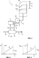
Der Fensterheber
Die Stellmechanik
Die Stellvorrichtung
Die Steuereinheit
Weiterhin wird der Steuereinheit
Die Steuereinheit
Um zu verhindern, dass die Fensterscheibe
Durch Multiplikation des Vorlaufs xV mit einer Richtungsvariable s, die beim Anheben der Fensterscheibe
Die Steuereinheit 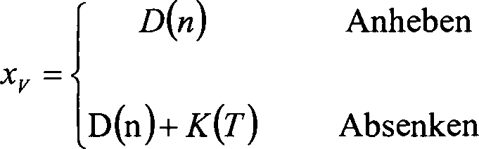
Die Steuereinheit
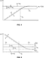
Ein exemplarischer Verlauf des Grundterms D und des Korrekturterms T ist in den
Aus
In
Der jeweilige Verlauf des Grundterms D und des Korrekturterms K wird vorzugsweise empirisch anhand von Laborversuchen an mindestens einem Testexemplar des Fensterherbers
In
Aufgrund ihrer eigenen mechanischen Trägheit sowie durch die Elastizität der Stellmechanik
Der Grundterm D des Vorlaufs xV ist nun derart gewählt, dass er der Summe des Nachlaufs x'N des Stellmotors
Obwohl die Erfindung an dem beschriebenen Ausführungsbeispiel besonders deutlich wird, ist sie auf dieses nicht beschränkt. Vielmehr können weitere Ausführungsformen der Erfindung von dem Fachmann aus der vorstehenden Beschreibung abgeleitet werden.Although the invention will be particularly apparent from the described embodiment, it is not limited to this. Rather, other embodiments of the invention may be derived by those skilled in the art from the foregoing description.
BezugszeichenlisteLIST OF REFERENCE NUMBERS
- 11
- Fensterheberpower windows
- 22
- (Fahrzeug-)Fensterscheibe(Vehicle) window
- 33
- Stellmotorservomotor
- 44
- Stellmechanikactuating mechanism
- 55
- StellwegTravel Range
- 66
- Öffnungsstellungopen position
- 77
- Schließstellungclosed position
- 88th
- Motorwellemotor shaft
- 99
- Antriebsschneckedrive worm
- 1010
- Schneckenradworm
- 1212
- Steuereinheitcontrol unit
- 1313
- DrehstellungssensorRotary position sensor
- 1414
- Temperatursensortemperature sensor
- xx
- Stellpositionsetting position
- SH S H
- Pulssignalpulse signal
- x'x '
- StellpositionsmaßStellpositionsmaß
- nn
- Drehzahlrotation speed
- TT
- (Temperatur-)Messwert(Temperature) measurement
- UM U M
- Betriebsspannungoperating voltage
- UB U B
- Batteriespannungbattery voltage
- x'A x ' A
- Abschaltpositionshutoff
- xZ x Z
- Zielpositiontarget position
- xV x V
- Vorlaufleader
- DD
- Grundtermground term
- KK
- Korrekturtermcorrection term
- nmin n min
- Grenzwertlimit
- nmax n max
- Grenzwertlimit
- Tmin T min
- Grenztemperaturlimit temperature
- Tmax T max
- Grenztemperaturlimit temperature
- tt
- ZeitTime
- tA t A
- Abschaltpunktswitch-off
- x'N x ' N
- Nachlauftrailing
- xN x N
- Nachlauftrailing
- xE x E
- Endpositionend position
Claims (6)
Priority Applications (4)
| Application Number | Priority Date | Filing Date | Title |
|---|---|---|---|
| DE102012024902.0A DE102012024902A1 (en) | 2012-12-20 | 2012-12-20 | Adjustment device for adjusting a movable vehicle part and method for operating the same |
| CN201380067361.1A CN104870736B (en) | 2012-12-20 | 2013-12-18 | Adjusting device for adjusting a movable vehicle part and method for operating it |
| US14/654,607 US9632510B2 (en) | 2012-12-20 | 2013-12-18 | Actuating device for adjusting a movable vehicle part and method for operating same |
| PCT/EP2013/077105 WO2014096012A1 (en) | 2012-12-20 | 2013-12-18 | Actuating device for adjusting a movable vehicle part and method for operating same |
Applications Claiming Priority (1)
| Application Number | Priority Date | Filing Date | Title |
|---|---|---|---|
| DE102012024902.0A DE102012024902A1 (en) | 2012-12-20 | 2012-12-20 | Adjustment device for adjusting a movable vehicle part and method for operating the same |
Publications (1)
| Publication Number | Publication Date |
|---|---|
| DE102012024902A1 true DE102012024902A1 (en) | 2014-06-26 |
Family
ID=49917052
Family Applications (1)
| Application Number | Title | Priority Date | Filing Date |
|---|---|---|---|
| DE102012024902.0A Withdrawn DE102012024902A1 (en) | 2012-12-20 | 2012-12-20 | Adjustment device for adjusting a movable vehicle part and method for operating the same |
Country Status (4)
| Country | Link |
|---|---|
| US (1) | US9632510B2 (en) |
| CN (1) | CN104870736B (en) |
| DE (1) | DE102012024902A1 (en) |
| WO (1) | WO2014096012A1 (en) |
Cited By (4)
| Publication number | Priority date | Publication date | Assignee | Title |
|---|---|---|---|---|
| DE102015205207A1 (en) * | 2015-03-23 | 2016-09-29 | Brose Fahrzeugteile Gmbh & Co. Kommanditgesellschaft, Bamberg | Method for operating an adjusting device and adjusting device with a temperature function implemented in an electronic control system |
| EP3390162A1 (en) * | 2015-12-18 | 2018-10-24 | Robert Bosch GmbH | Electric servo drive for a motor vehicle |
| EP3650627A1 (en) * | 2018-11-07 | 2020-05-13 | Inalfa Roof Systems Group B.V. | Method and device for accurate positioning of a moveably arranged panel |
| CN112227873A (en) * | 2020-10-29 | 2021-01-15 | 马力达汽车电子(宁波)有限公司 | Motor respiration rainfall monitoring system and method based on temperature and rainfall monitoring |
Families Citing this family (2)
| Publication number | Priority date | Publication date | Assignee | Title |
|---|---|---|---|---|
| JP7040472B2 (en) * | 2019-01-25 | 2022-03-23 | 株式会社デンソー | Open / close body control device |
| US11505238B2 (en) * | 2020-03-03 | 2022-11-22 | Steering Solutions Ip Holding Corporation | Handwheel position measurement system and method |
Family Cites Families (11)
| Publication number | Priority date | Publication date | Assignee | Title |
|---|---|---|---|---|
| DE4442171A1 (en) | 1994-11-26 | 1996-06-13 | Telefunken Microelectron | Method for monitoring the opening and closing process in a system with at least one electromotive part |
| DE19632910C2 (en) | 1996-08-16 | 2002-07-25 | Brose Fahrzeugteile | Method for non-contact approaching the lower stop position of a power window of a motor vehicle |
| JP2001014002A (en) | 1999-06-30 | 2001-01-19 | Yazaki Corp | Backup method when microcomputer stops operation, backup device for microcomputer, and power window control device for automobile |
| ES2155413B1 (en) * | 1999-10-22 | 2002-02-01 | Castellon Melchor Daumal | IMPROVEMENTS IN THE ANTIPINZING SYSTEMS INTENDED FOR THE CAR. |
| DE10026991A1 (en) | 2000-05-31 | 2001-12-13 | Bosch Gmbh Robert | Method for positioning an externally operated closing surface |
| US6678601B2 (en) * | 2002-05-31 | 2004-01-13 | Valeo Electrical Systems, Inc. | Motor speed-based anti-pinch control apparatus and method with rough road condition detection and compensation |
| US20060000558A1 (en) * | 2005-09-13 | 2006-01-05 | James Fennell | Solar-Powered, Low-Voltage, Automatic, Motorized Exterior Window Shading Device |
| US7812554B2 (en) * | 2006-10-06 | 2010-10-12 | Omron Corporation | Control device for opening/closing member |
| DE102010009821A1 (en) | 2010-03-02 | 2011-09-08 | Brose Fahrzeugteile Gmbh & Co. Kommanditgesellschaft, Hallstadt | Method for determining the setting position of an adjustment part |
| CN102785556B (en) | 2012-08-23 | 2015-02-04 | 北京经纬恒润科技有限公司 | Method and system for controlling operation of car sunroof |
| US9174514B2 (en) * | 2013-08-15 | 2015-11-03 | Honda Motor Co., Ltd. | Glass operation based on temperature input/vehicle speed, final logic decided by customer |
-
2012
- 2012-12-20 DE DE102012024902.0A patent/DE102012024902A1/en not_active Withdrawn
-
2013
- 2013-12-18 WO PCT/EP2013/077105 patent/WO2014096012A1/en not_active Ceased
- 2013-12-18 US US14/654,607 patent/US9632510B2/en not_active Expired - Fee Related
- 2013-12-18 CN CN201380067361.1A patent/CN104870736B/en not_active Expired - Fee Related
Cited By (5)
| Publication number | Priority date | Publication date | Assignee | Title |
|---|---|---|---|---|
| DE102015205207A1 (en) * | 2015-03-23 | 2016-09-29 | Brose Fahrzeugteile Gmbh & Co. Kommanditgesellschaft, Bamberg | Method for operating an adjusting device and adjusting device with a temperature function implemented in an electronic control system |
| EP3390162A1 (en) * | 2015-12-18 | 2018-10-24 | Robert Bosch GmbH | Electric servo drive for a motor vehicle |
| EP3650627A1 (en) * | 2018-11-07 | 2020-05-13 | Inalfa Roof Systems Group B.V. | Method and device for accurate positioning of a moveably arranged panel |
| US11479093B2 (en) | 2018-11-07 | 2022-10-25 | Inalfa Roof Systems Group B.V. | Method and device for accurate positioning of a moveably arranged panel |
| CN112227873A (en) * | 2020-10-29 | 2021-01-15 | 马力达汽车电子(宁波)有限公司 | Motor respiration rainfall monitoring system and method based on temperature and rainfall monitoring |
Also Published As
| Publication number | Publication date |
|---|---|
| US9632510B2 (en) | 2017-04-25 |
| CN104870736B (en) | 2016-09-21 |
| US20160077528A1 (en) | 2016-03-17 |
| CN104870736A (en) | 2015-08-26 |
| WO2014096012A1 (en) | 2014-06-26 |
Similar Documents
| Publication | Publication Date | Title |
|---|---|---|
| DE102012024902A1 (en) | Adjustment device for adjusting a movable vehicle part and method for operating the same | |
| DE19632910C2 (en) | Method for non-contact approaching the lower stop position of a power window of a motor vehicle | |
| DE102012008235B4 (en) | Precise positioning detection in a motor-driven vehicle part | |
| DE102007056228B4 (en) | Method and device for correcting temperature-dependent changes in the mechanical properties of a movable closing part of a vehicle | |
| DE19758796B4 (en) | Method for controlling and regulating the adjustment movement of a translationally adjustable component in vehicles | |
| DE102011111450A1 (en) | Method and device for monitoring a drive unit having a rotating drive motor, in particular a window lifter | |
| DE102015120750A1 (en) | Control device for an openable and closable member | |
| DE102014009714A1 (en) | Window lift for a vehicle and method of operating such | |
| DE102015119799A1 (en) | Drive arrangement for a closure element of a motor vehicle | |
| DE102010055650A1 (en) | Method and device for controlling an adjusting device of a motor vehicle | |
| EP2760129B1 (en) | Positioning device for a moveable motor vehicle part | |
| EP2999838A1 (en) | Anti-trap protection system for a window in a vehicle door, comprising a closing aid | |
| EP1292459B1 (en) | Method for determining the position of an element driven by the drive shaft of a direct current motor | |
| DE102016220151B4 (en) | Method and system for determining the position of a vehicle outer part | |
| DE102018211205A1 (en) | Actuating device for a vehicle door and method for operating the actuating device | |
| DE102015217895A1 (en) | Control method for a window regulator of a convertible with a motorized convertible top | |
| DE102011110081A1 (en) | Method for controlling electromotive adjusting drive of e.g. windshield of motor vehicle, involves controlling rotational speed of motor in response to manual or automatic operating stage triggered by operating element | |
| DE102020213733A1 (en) | Method for adjusting a motor vehicle part that can be adjusted by a motor and associated adjusting device | |
| DE102013201448B4 (en) | Method and device for operating an electric window lifter system, as well as a window lifter system and its use in a vehicle door | |
| DE102016205325A1 (en) | Adjusting device for an adjustable vehicle part and method for operating such | |
| EP2118981B1 (en) | Calibrating a powered actuator | |
| DE102017115024A1 (en) | Drive arrangement for a flap of a motor vehicle | |
| DE102015226108A1 (en) | Anti-jamming method for carrying out a motorized adjusting device for an adjustable vehicle part and associated adjusting device | |
| DE102011121410B4 (en) | A flap device for a vehicle and method for operating a flap device and vehicle with a flap device | |
| EP1053515B1 (en) | Method for positioning a part |
Legal Events
| Date | Code | Title | Description |
|---|---|---|---|
| R081 | Change of applicant/patentee |
Owner name: BROSE FAHRZEUGTEILE GMBH & CO. KOMMANDITGESELL, DE Free format text: FORMER OWNER: BROSE FAHRZEUGTEILE GMBH & CO. KOMMANDITGESELLSCHAFT, HALLSTADT, 96103 HALLSTADT, DE |
|
| R082 | Change of representative |
Representative=s name: FDST PATENTANWAELTE FREIER DOERR STAMMLER TSCH, DE |
|
| R005 | Application deemed withdrawn due to failure to request examination |