DE102021101552B4 - Arrangement of an exhaust nozzle for a mobile air conditioner at a window gap - Google Patents
Arrangement of an exhaust nozzle for a mobile air conditioner at a window gap Download PDFInfo
- Publication number
- DE102021101552B4 DE102021101552B4 DE102021101552.9A DE102021101552A DE102021101552B4 DE 102021101552 B4 DE102021101552 B4 DE 102021101552B4 DE 102021101552 A DE102021101552 A DE 102021101552A DE 102021101552 B4 DE102021101552 B4 DE 102021101552B4
- Authority
- DE
- Germany
- Prior art keywords
- exhaust air
- nozzle
- inlet
- window
- hollow body
- Prior art date
- Legal status (The legal status is an assumption and is not a legal conclusion. Google has not performed a legal analysis and makes no representation as to the accuracy of the status listed.)
- Active
Links
Images
Classifications
-
- F—MECHANICAL ENGINEERING; LIGHTING; HEATING; WEAPONS; BLASTING
- F24—HEATING; RANGES; VENTILATING
- F24F—AIR-CONDITIONING; AIR-HUMIDIFICATION; VENTILATION; USE OF AIR CURRENTS FOR SCREENING
- F24F13/00—Details common to, or for air-conditioning, air-humidification, ventilation or use of air currents for screening
- F24F13/02—Ducting arrangements
- F24F13/0227—Ducting arrangements using parts of the building, e.g. air ducts inside the floor, walls or ceiling of a building
Landscapes
- Engineering & Computer Science (AREA)
- Chemical & Material Sciences (AREA)
- Combustion & Propulsion (AREA)
- Mechanical Engineering (AREA)
- General Engineering & Computer Science (AREA)
- Air-Flow Control Members (AREA)
- Duct Arrangements (AREA)
Abstract
Die Erfindung betrifft eine Anordnung einer Abluftdüse (10) für ein mobiles Klimagerät zum Ableiten von Abluft des mobilen Klimageräts aus einem Fensterspalt, aufweisend einen Einlasshohlkörper (11) mit einem Einlassstutzen (12) zur Verbindung mit einem Abluftschlauch des mobilen Klimageräts, an den sich ein Abluftkanal (13) mit einem rechteckigen Querschnitt anschließt, der einen Auslass (14) für die Abluft aufweist. Die Abluftdüse (10) zeichnet sich dadurch aus, dass der Einlasshohlkörper (11) ein Prisma mit einer im Wesentlichen dreieckigen Grundfläche (114) ist, sowie einer Mantelfläche, die eine Frontseite (111) des Einlasshohlkörpers (11) aufweist, auf der der Einlassstutzen (12) angeordnet ist, eine Auflageseite (112), mit der die Abluftdüse auf oder an einem Flügelrahmen (7) eines Fensters (5) anliegt, und eine Rückseite (113), auf die ein in den Lufteinlassstutzen (12) eintretender Luftstrom auftrifft.The invention relates to an arrangement of an exhaust air nozzle (10) for a mobile air conditioning unit for discharging exhaust air from the mobile air conditioning unit from a window gap, comprising an inlet hollow body (11) with an inlet nozzle (12) for connection to an exhaust air hose of the mobile air conditioning unit, to which an exhaust air duct (13) with a rectangular cross-section is connected, which has an outlet (14) for the exhaust air. The exhaust air nozzle (10) is characterized in that the inlet hollow body (11) is a prism with a substantially triangular base area (114) and a lateral surface which has a front side (111) of the inlet hollow body (11) on which the inlet nozzle (12) is arranged, a support side (112) with which the exhaust air nozzle rests on or against a sash frame (7) of a window (5), and a rear side (113) on which an air flow entering the air inlet nozzle (12) strikes.
Description
Die Erfindung betrifft eine Anordnung einer Abluftdüse an einem Fensterspalt zum Ableiten von Abluft eines mobilen Klimageräts aus dem Fensterspalt, insbesondere eines gekippten Fensters. Die Abluftdüse weist einen Einlasshohlkörper mit einem Einlassstutzen zur Verbindung mit einem Abluftschlauch des mobilen Klimageräts auf. An den Einlasshohlkörper schließt sich ein Abluftkanal mit einem rechteckigen Querschnitt an, der einen Auslass aufweist, aus dem die Abluft des mobilen Klimageräts an die Umgebung abgegeben wird.The invention relates to an arrangement of an exhaust air nozzle on a window gap for discharging exhaust air from a mobile air conditioning unit from the window gap, in particular from a tilted window. The exhaust air nozzle has an inlet hollow body with an inlet connection for connection to an exhaust air hose of the mobile air conditioning unit. The inlet hollow body is followed by an exhaust air duct with a rectangular cross-section, which has an outlet from which the exhaust air from the mobile air conditioning unit is released into the environment.
Bei einem Betrieb mobiler Klimageräte fällt aufgewärmte Abluft an, die aus einem Gebäude heraus nach außen abgegeben werden muss. Damit vergleichbar muss auch Abluft von Trocknungsgeräten, die zur Trocknung einer Bausubstanz eines Gebäudes in der Bauphase oder nach einem Wasserschaden verwendet werden, oder von bestimmten Arten von Luftreinigungsgeräten nach außen geführt werden.When mobile air conditioning units are operated, heated exhaust air is produced that must be released from a building to the outside. In a similar way, exhaust air from drying devices that are used to dry the structure of a building during the construction phase or after water damage, or from certain types of air purification devices, must also be led outside.
Nicht immer können geeignete Abluftmöglichkeiten, z.B. in Form einer Mauerdurchführung, bereitgestellt werden, um die Abluft nach außen abgeben zu können. In der Regel bieten sich dann Fenster als Gebäudeöffnungen an, durch die ein Abluftschlauch des mobilen Klimageräts nach außen gelegt werden kann. Dazu besteht die Möglichkeit, das Fenster ganz oder teilweise aufzuschwenken und den Abluftschlauch durchzuführen. Der Fensterflügel wird in der ganz oder teilweise geöffneten Stellung fixiert und der außerhalb des Schlauchs verbleibende Fensterspalt durch eine angepasste Verkleidung verschlossen. Dieses ist zum einen aufwendig und zum anderen aus Gründen der Einbruchsicherheit unbefriedigend. Eine andere Möglichkeit besteht darin, den Abluftschlauch durch den Spalt bei einem gekippten Fenster zu führen. Aufgrund des üblicherweise genutzten Schlauchdurchmessers im Bereich von 10-15 Zentimetern (cm) ist dieses nicht in allen Fällen möglich.Suitable exhaust air options, e.g. in the form of a wall duct, cannot always be provided to allow the exhaust air to be released to the outside. Windows are usually suitable as building openings through which an exhaust air hose from the mobile air conditioning unit can be laid to the outside. To do this, it is possible to swing the window fully or partially open and run the exhaust air hose through. The window sash is fixed in the fully or partially open position and the window gap remaining outside the hose is closed off with an adapted panel. This is both time-consuming and unsatisfactory in terms of burglary protection. Another option is to run the exhaust air hose through the gap in a tilted window. Due to the hose diameter usually used in the range of 10-15 centimeters (cm), this is not possible in all cases.
Es sind am Markt Abluftdüsen bekannt, durch die der Schlauchdurchmesser im Bereich des Fensterspalts bei einem gekippten Fenster reduziert wird und in einen im Wesentlichen rechteckigen Abluftkanal übergeht, der durch den Fensterspalt gesteckt wird und durch den die Abluft des mobilen Klimageräts nach außen abgegeben werden kann. Bei den bekannten Abluftdüsen dieser Art führt die Querschnittsveränderung jedoch zum einen zu starken Abluftgeräuschen und zum anderen zu einer Erhöhung des Schlauchwiderstands, der die Effektivität der mobilen Klimageräte verringert. Zudem sind die im Markt erhältlichen Abluftdüsen umständlich in ihrer Handhabung, da sie ohne spezielle Befestigung dazu neigen, aus dem Fensterspalt herauszurutschen.There are exhaust air nozzles on the market that reduce the diameter of the hose in the area of the window gap when the window is tilted, and that merge into an essentially rectangular exhaust air duct that is inserted through the window gap and through which the exhaust air from the mobile air conditioning unit can be released to the outside. However, with the known exhaust air nozzles of this type, the change in cross-section leads to loud exhaust air noise on the one hand and to an increase in hose resistance on the other, which reduces the effectiveness of the mobile air conditioning units. In addition, the exhaust air nozzles available on the market are cumbersome to use, as they tend to slip out of the window gap without special fastening.
Vergleichbare Abluftdüsen für mobile Klimageräte zeigen die Druckschriften
Aus der Druckschrift
Es ist eine Aufgabe der vorliegenden Erfindung, eine Anordnung einer Abluftdüse an einem Fensterspalt zu schaffen, die die Effektivität des mobilen Klimageräts möglichst wenig beeinflusst, bei der die Abgabe der Abluft mit möglichst geringer Geräuschemission erfolgt und bei der die Abluftdüse einfach und sicher in der Handhabung ist.It is an object of the present invention to provide an arrangement of an exhaust air nozzle on a window gap which influences the effectiveness of the mobile air conditioning unit as little as possible, in which the exhaust air is discharged with as little noise emission as possible and in which the exhaust air nozzle is simple and safe to handle.
Diese Aufgabe wird durch eine Anordnung einer Abluftdüse an einem Fensterspalt mit den Merkmalen des unabhängigen Anspruchs gelöst. Vorteilhafte Ausgestaltungen und Weiterbildungen sind Gegenstand der abhängigen Ansprüche.This object is achieved by arranging an exhaust air nozzle on a window gap with the features of the independent claim. Advantageous embodiments and further developments are the subject of the dependent claims.
Eine anmeldungsgemäße Anordnung der eingangs genannten Art zeichnet sich dadurch aus, dass der Einlasshohlkörper der Abluftdüse ein Prisma mit einer dreieckigen Grundfläche ist, dessen Mantelfläche eine Frontseite des Einlasshohlkörpers aufweist, auf der der Einlassstutzen angeordnet ist, eine Auflageseite, mit der die Abluftdüse auf oder an einem Flügelrahmen eines Fensters anliegt und die senkrecht zu der Frontseite angeordnet ist, und eine Rückseite, auf die ein in den Einlassstutzen eintretender Luftstrom auftrifft.An arrangement of the type mentioned at the outset according to the application is characterized in that the inlet hollow body of the exhaust air nozzle is a prism with a triangular base, the outer surface of which has a front side of the inlet hollow body on which the inlet nozzle is arranged, a support side with which the exhaust air nozzle rests on or against a sash frame of a window and which is arranged perpendicular to the front side, and a rear side on which an air flow entering the inlet nozzle strikes.
Die so gestaltete Abluftdüse kann zur Anordnung mit ihrem Abluftkanal in den Fensterspalt, bevorzugt den oberen waagerecht verlaufenden Fensterspalt bei einem gekippten Fenster, eingeführt werden. Durch den im Profil in einer Richtung quer zum Luftstrom dreieckig ausgebildeten Einlasshohlkörper wird die Auflageseite bereitgestellt, die auf dem Rand eines Flügelrahmens des gekippten Fensters aufliegt, wodurch die Abluftdüse sicher in dieser Position gehalten wird und das Gewicht und die Zugkräfte eines angeschlossenen Abluftschlauchs aufnehmen kann, ohne aus dem Fensterspalt zu rutschen. Gleichzeitig bedingt die im Profil dreieckige Form des Einlasshohlkörpers, dass die Rückwand desselben geneigt zu dem durch den Einlassstutzen eintretenden Luftstrom steht. Dadurch wird der Luftstrom in Richtung des Abluftkanals umgelenkt, wodurch der Strömungswiderstand und die Geräuschentwicklung möglichst gering bleiben.The exhaust air nozzle designed in this way can be inserted into the window gap with its exhaust air duct, preferably the upper horizontal window gap with a tilted window. The inlet hollow body, which is triangular in profile in a direction perpendicular to the air flow, provides the support side that rests on the edge of a sash frame of the tilted window, whereby the exhaust air nozzle is held securely in this position and can absorb the weight and tensile forces of a connected exhaust air hose without slipping out of the window gap. At the same time, the triangular shape of the inlet hollow body in profile means that the rear wall of the same is inclined to the air flow entering through the inlet nozzle. This redirects the air flow in the direction of the exhaust air duct, which keeps the flow resistance and noise development as low as possible.
In einer vorteilhaften Weiterbildung der Anordnung stehen die Auflageseite und die Frontseite der Abluftdüse senkrecht aufeinander. Weiter bevorzugt liegt die Rückseite in einer Ebene mit einer Oberseite des Abluftkanals, d.h. dass die Rückseite des Einlasshohlkörpers gerade in die Oberseite des Abluftkanals übergeht. Auch dadurch wird ein Luftwiderstand innerhalb der Abluftdüse möglichst klein gehalten.In an advantageous further development of the arrangement, the support side and the front side of the exhaust air nozzle are perpendicular to one another. The rear side is also preferably in the same plane as the top side of the exhaust air duct, i.e. the rear side of the hollow inlet body merges directly into the top side of the exhaust air duct. This also keeps air resistance within the exhaust air nozzle as small as possible.
Bevorzugt ist zwischen der Frontseite und der Rückseite des Einlasshohlkörpers ein spitzer Winkel gebildet, der vorteilhaft im Bereich von 20-50° und besonders bevorzugt im Bereich von 30-40°, beispielsweise bei etwa 35°, liegt. Der Winkel zwischen der Auflageseite und einer Unterseite des Abluftkanals ist dann bevorzugt ein stumpfer Winkel im Bereich von 110-140° und besonders vorteilhaft im Bereich von 120-130°, beispielsweise bei etwa 125°. Durch diese Geometrie kann der spitze Winkel zwischen der Frontseite und der Rückseite des Einlasshohlkörpers außerhalb einer Fensternische positioniert sein, was einen Einsatz der Abluftdüse in einem oberen Fensterspalt bei einem gekippten Fenster auch dann ermöglicht, wenn zwischen einem Flügelrahmen des Fensters und dem Fenstersturz nur wenig Platz ist.Preferably, an acute angle is formed between the front and the rear of the hollow inlet body, which is advantageously in the range of 20-50° and particularly preferably in the range of 30-40°, for example at around 35°. The angle between the support side and a bottom of the exhaust air duct is then preferably an obtuse angle in the range of 110-140° and particularly advantageously in the range of 120-130°, for example at around 125°. This geometry allows the acute angle between the front and the rear of the hollow inlet body to be positioned outside a window niche, which enables the exhaust air nozzle to be used in an upper window gap with a tilted window even when there is little space between a window sash and the window lintel.
In einer weiteren vorteilhaften Weiterbildung der Anordnung weist der Abluftkanal der Abluftdüse zwei Abschnitte auf, die winkelig zueinander ausgerichtet sind. Insbesondere ist der Abschnitt, in dem sich der Auslass befindet, also der äußere Abschnitt des Abluftkanals, zum Einlasshohlkörper hin abgewinkelt, sodass er beim Einsatz im Fenster in Richtung der Fensterscheibe abgewinkelt ist. Der Winkel kann beispielsweise in einem Bereich von 140-170° und bevorzugt von 150-160° liegen. Der von der Abluftdüse abgegebene Abluftstrom wird so beispielsweise nicht so stark in Richtung eines vor dem Gebäude verlaufenden Gehwegs geblasen. Dieser Effekt kann auch durch eine zusätzlich an einer Seite des Abluftkanals hervorstehende abgewinkelte Lippe verstärkt werden. Die abgewinkelte Form des Abluftkanals beeinflusst zudem die Gewichtsverteilung der Abluftdüse vorteilhaft, sodass diese auch dann sicher auf dem gekippten Flügelrahmen sitzt, wenn kein Abluftschlauch angeschlossen ist.In a further advantageous development of the arrangement, the exhaust air duct of the exhaust air nozzle has two sections that are aligned at an angle to one another. In particular, the section in which the outlet is located, i.e. the outer section of the exhaust air duct, is angled towards the inlet hollow body so that when used in the window it is angled towards the window pane. The angle can, for example, be in a range of 140-170° and preferably 150-160°. The exhaust air flow emitted by the exhaust air nozzle is therefore not blown so strongly in the direction of a walkway in front of the building, for example. This effect can also be reinforced by an additional angled lip protruding on one side of the exhaust air duct. The angled shape of the exhaust air duct also has a beneficial effect on the weight distribution of the exhaust air nozzle, so that it sits securely on the tilted sash frame even when no exhaust air hose is connected.
Bei einer weiteren vorteilhaften Ausgestaltung der Anordnung entspricht die Querschnittsfläche des Abluftkanals in etwa der Querschnittsfläche des Einlassstutzens. So wird verhindert, dass der Abluftkanal selbst einen erhöhten Luftwiderstand für die Abluftdüse bildet.In a further advantageous embodiment of the arrangement, the cross-sectional area of the exhaust air duct corresponds approximately to the cross-sectional area of the inlet nozzle. This prevents the exhaust air duct itself from creating increased air resistance for the exhaust air nozzle.
In einer weiteren vorteilhaften Ausgestaltung der Anordnung ist die Abluftdüse aus Metallblech gefertigt, z.B. aus abgekanteten und miteinander vernieteten Blechelementen. Sie kann auf diese Weise robust und gleichzeitig kostengünstig gefertigt werden. Ein gegenüber anderen Materialien erhöhtes Gewicht ist im Hinblick auf einen guten Sitz der Abluftdüse im Fensterspalt zudem vorteilhaft.In a further advantageous embodiment of the arrangement, the exhaust air nozzle is made of sheet metal, e.g. from bent sheet metal elements riveted together. In this way, it can be manufactured robustly and at the same time inexpensively. A higher weight compared to other materials is also advantageous with regard to a good fit of the exhaust air nozzle in the window gap.
Die Erfindung wird nachfolgend anhand eines Ausführungsbeispiels mithilfe von Figuren näher erläutert. Die Figuren zeigen:
-
1 ,2 jeweils eine perspektivische Ansicht eines gekippten Fensters mit einer eingesetzten Abluftdüse aus verschiedenen Blickrichtungen; -
3 ,4 jeweils eine perspektivische Ansicht der Abluftdüse der1 und2 aus verschiedenen Blickrichtungen; und -
5 die Abluftdüse der vorherigen Figuren eingesetzt in einen seitlichen Fensterspalt eines gekippten Fensters.
-
1 ,2 a perspective view of a tilted window with an inserted exhaust air nozzle from different viewing directions; -
3 ,4 a perspective view of the exhaust nozzle of the1 and2 from different perspectives; and -
5 The exhaust air nozzle of the previous figures is inserted into a side window gap of a tilted window.
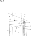
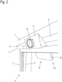
In den
Das Fenster ist gekippt, sodass im Bereich der Laibung 3 ein schmaler, sich nach oben aufweitender Spalt gebildet wird und im Bereich des Sturzes 4 ein größerer, über seine Länge gleichmäßig breiter Spalt.The window is tilted so that a narrow gap widening upwards is formed in the area of the
In diesen oberen breiteren Spalt ist eine Abluftdüse 10 eingesetzt. Sie weist einen im Profil dreieckigen, prismenförmigen Einlasshohlkörper 11, nachfolgend vereinfacht als Einlasskasten 11 bezeichnet, auf, an dem sich ein Einlassstutzen 12 befindet. Dieser Einlassstutzen 12 wird im Betrieb der Abluftdüse 10 mit einem Abluftschlauch eines mobilen Klimageräts oder auch eines Trocknungsgeräts verbunden. Typische Abluftschläuche dafür weisen einen Durchmesser im Bereich von 10-15 cm auf, an denen der Außendurchmesser des Einlassstutzens 12 angepasst ist.An
Mit dem Einlasskasten 11 der Abluftdüse 10 ist ein Abluftkanal 13 verbunden, der durch den Fensterspalt nach außen ragt. Der Abluftkanal 13 hat einen rechteckigen Querschnitt und weist eine Dicke im Bereich von einigen Zentimetern auf. Der Abluftkanal 13 ist an der dem Einlasskasten 11 gegenüberliegenden Seite offen, so dass ein hier schlitzförmiger Auslass 14 für die Abluft gebildet wird. In ihrer Breite (Ausdehnung in Richtung des Fensterspalts) sind der Einlasskasten 11 und der Abluftkanal 13 gleich. Die Breite liegt im Bereich von einigen zehn Zentimetern. Mit diesen Abmessungen kann der Abluftkanal 13 problemlos in den bei Fenstern üblicher Größe bestehenden Fensterspalt eingesetzt werden.An
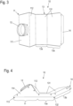
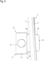
Details des Aufbaus der Abluftdüse 10 sind in den beiden perspektivischen Zeichnungen in den
Auf der Frontseite 111 ist der bereits genannte Einlassstutzen 12 mittig angeordnet. Senkrecht zur Frontseite 111 steht die Auflageseite 112, die beim Einsetzen der Abluftdüse 10 auf der Oberseite des gekippten Fensters 5 aufliegt. Durch die Auflageseite 112 kann die Abluftdüse 10 sicher auf den Fensterrahmen aufgesetzt werden. Die flächige Auflage über die gesamte Breite der Abluftdüse 10 verhindert Beschädigungen an der Oberfläche des Flügelrahmens 7.The
Durch die dreieckige Prismenform des Einlasskastens 11 ist die dem Einlassstutzen 12 gegenüberliegende Rückseite 113 geneigt in dem Luftstrom der Abluft, die in den Einlassstutzen 12 einströmt, angeordnet. Auf diese Weise wird die Abluft mit geringem Strömungswiderstand in Richtung des sich anschließenden Abluftkanals 13 geleitet.Due to the triangular prism shape of the
Der Abluftkanal 13 weist eine Unterseite 131 und eine parallel dazu ausgerichtete Oberseite 132 auf, wobei die Oberseite 132 und die Rückseite 113 des Einlasskastens 11 in einer Ebene liegen und nahtlos und gerade ineinander übergehen. Letzteres ist zum einen strömungstechnisch günstig und trägt zum anderen den häufig sehr beengten Platzverhältnissen zwischen der Oberseite des Flügelrahmens 7 und dem Sturz 4 Rechnung. Zwischen der Frontseite 111 und der Rückseite 113 ist durch die dreieckige Form des Einlasskastens 11 ein spitzer Winkel gebildet, der auch bei geringem Abstand zwischen Flügelrahmen 7 und Sturz 4 außerhalb der Fensternische 2 vor der Wand 1 positioniert sein kann. Der Winkel, in dem die Frontseite 111 zur Rückseite 113 steht, liegt vorteilhaft im Bereich von 20-50° und besonders bevorzugt im Bereich von 30-40°, beispielsweise 35°. Der Winkel zwischen der Auflageseite 112 und der Unterseite 131 des Abluftkanals 13 ist dann bevorzugt ein stumpfer Winkel im Bereich von 110-140° und besonders vorteilhaft im Bereich von 120-130°, beispielsweise 125°.The
Der Abluftkanal 13 kann in einer Ausgestaltung gerade bis zum Auslass 14 ausgeführt sein. Beim dargestellten Beispiel ist er dagegen in etwa in der Mitte gewinkelt ausgebildet, sodass er zwei Abschnitte 13a, 13b aufweist, die im Bereich von 150-160°, beispielsweise 155° zueinanderstehen. Durch die gewinkelte Ausführung des Abluftkanals 13 ragt der Auslass 14 weniger weit vom Gebäude weg nach außen, was eine Stoßgefahr im Bereich von erdnahen Fenstern, beispielsweise bei Souterrain-Wohnungen, verringert. Zudem wird der Abluftstrom weniger stark in Richtung eines z. B. vor dem Gebäude verlaufenden Wegs gerichtet, was andernfalls als störend empfunden werden könnte. Dieser Effekt wird durch eine Verlängerung der Oberseite 132 in Form einer abgewinkelten Lippe 141 verstärkt.In one embodiment, the
Schließlich führt die gewinkelte Ausführung des Abluftkanals 13 zu einer günstigeren Gewichtsverteilung der Abluftdüse 10, durch die der Sitz der Abluftdüse 10 auf dem Flügelrahmen 7 weiter gefestigt wird, insbesondere wenn kein Abluftschlauch angeschlossen ist. In dem Fall könnte die Abluftdüse 10 ansonsten bei zu weit nach außen ragendem Abluftkanal 13 dazu neigen, nach außen von der Kante des Flügelrahmens zu rutschen.Finally, the angled design of the
Bezugszeichenlistelist of reference symbols
- 11
- WandWall
- 22
- Fensternischewindow niche
- 33
- Laibungreveal
- 44
- Sturzfall
- 55
- FensterWindow
- 66
- Blendrahmenframe
- 77
- Flügelrahmensash frame
- 1010
- Abluftdüseexhaust nozzle
- 1111
- Einlasshohlkörper (Einlasskasten)inlet hollow body (inlet box)
- 111111
- Frontseitefront
- 112112
- Auflageseitesupport side
- 113113
- Rückseiteback
- 114114
- Grundflächefloor space
- 1212
- Einlassstutzeninlet nozzle
- 1313
- Abluftkanalexhaust air duct
- 131131
- Unterseitebottom
- 132132
- Oberseitetop
- 13 a, b13 a, b
- Abschnitte des Abluftkanalssections of the exhaust air duct
- 1414
- Auslassoutlet
- 141141
- Lippelip
Claims (8)
Priority Applications (1)
| Application Number | Priority Date | Filing Date | Title |
|---|---|---|---|
| DE102021101552.9A DE102021101552B4 (en) | 2021-01-25 | 2021-01-25 | Arrangement of an exhaust nozzle for a mobile air conditioner at a window gap |
Applications Claiming Priority (1)
| Application Number | Priority Date | Filing Date | Title |
|---|---|---|---|
| DE102021101552.9A DE102021101552B4 (en) | 2021-01-25 | 2021-01-25 | Arrangement of an exhaust nozzle for a mobile air conditioner at a window gap |
Publications (2)
| Publication Number | Publication Date |
|---|---|
| DE102021101552A1 DE102021101552A1 (en) | 2022-07-28 |
| DE102021101552B4 true DE102021101552B4 (en) | 2025-02-13 |
Family
ID=82320559
Family Applications (1)
| Application Number | Title | Priority Date | Filing Date |
|---|---|---|---|
| DE102021101552.9A Active DE102021101552B4 (en) | 2021-01-25 | 2021-01-25 | Arrangement of an exhaust nozzle for a mobile air conditioner at a window gap |
Country Status (1)
| Country | Link |
|---|---|
| DE (1) | DE102021101552B4 (en) |
Families Citing this family (1)
| Publication number | Priority date | Publication date | Assignee | Title |
|---|---|---|---|---|
| DE102024114810A1 (en) * | 2024-05-27 | 2025-11-27 | Felix Christopher Joachim Radisch | Exhaust nozzle for venting exhaust air through a window gap of a tilt window. |
Citations (10)
| Publication number | Priority date | Publication date | Assignee | Title |
|---|---|---|---|---|
| US867571A (en) | 1907-05-11 | 1907-10-08 | Emil L Claus | Gas-cock. |
| US5338255A (en) | 1993-01-22 | 1994-08-16 | Noll Manufacturing Co. | Air duct fitting mounting shoulder |
| DE19533226A1 (en) | 1995-09-08 | 1996-02-22 | Klaus Dr Ing Manns | Window attachable ventilation hose for tumble dryer |
| JP2004169997A (en) * | 2002-11-20 | 2004-06-17 | Matsushita Ecology Systems Co Ltd | Ventilating device attachable to window |
| DE202006000695U1 (en) | 2006-01-18 | 2006-04-27 | HECK, Jürgen | Ventilation device in humid rooms, e.g. bathrooms, has mobile and stationary variants, hinged parts that guide air during operation brought into their operating positions to start operating and to form air shaft of ventilation device |
| WO2014015356A2 (en) | 2012-07-25 | 2014-01-30 | Ets Egger Gmbh | Air guiding device |
| DE202018004915U1 (en) * | 2018-10-01 | 2018-11-15 | Said Mansoubi | Device for transporting air |
| DE202019000068U1 (en) * | 2019-01-07 | 2019-02-04 | Andreas Fritsche | Multifunctional electric fan / ventilation system for tilting windows & tilting doors |
| USD867571S1 (en) * | 2017-06-20 | 2019-11-19 | Bsh Home Appliances Corporation | Ventilation hood |
| DE102018007113A1 (en) * | 2018-09-08 | 2020-03-12 | Joachim Friedrich Schug | Clamping funnel in the window for air conditioning applications |
-
2021
- 2021-01-25 DE DE102021101552.9A patent/DE102021101552B4/en active Active
Patent Citations (10)
| Publication number | Priority date | Publication date | Assignee | Title |
|---|---|---|---|---|
| US867571A (en) | 1907-05-11 | 1907-10-08 | Emil L Claus | Gas-cock. |
| US5338255A (en) | 1993-01-22 | 1994-08-16 | Noll Manufacturing Co. | Air duct fitting mounting shoulder |
| DE19533226A1 (en) | 1995-09-08 | 1996-02-22 | Klaus Dr Ing Manns | Window attachable ventilation hose for tumble dryer |
| JP2004169997A (en) * | 2002-11-20 | 2004-06-17 | Matsushita Ecology Systems Co Ltd | Ventilating device attachable to window |
| DE202006000695U1 (en) | 2006-01-18 | 2006-04-27 | HECK, Jürgen | Ventilation device in humid rooms, e.g. bathrooms, has mobile and stationary variants, hinged parts that guide air during operation brought into their operating positions to start operating and to form air shaft of ventilation device |
| WO2014015356A2 (en) | 2012-07-25 | 2014-01-30 | Ets Egger Gmbh | Air guiding device |
| USD867571S1 (en) * | 2017-06-20 | 2019-11-19 | Bsh Home Appliances Corporation | Ventilation hood |
| DE102018007113A1 (en) * | 2018-09-08 | 2020-03-12 | Joachim Friedrich Schug | Clamping funnel in the window for air conditioning applications |
| DE202018004915U1 (en) * | 2018-10-01 | 2018-11-15 | Said Mansoubi | Device for transporting air |
| DE202019000068U1 (en) * | 2019-01-07 | 2019-02-04 | Andreas Fritsche | Multifunctional electric fan / ventilation system for tilting windows & tilting doors |
Also Published As
| Publication number | Publication date |
|---|---|
| DE102021101552A1 (en) | 2022-07-28 |
Similar Documents
| Publication | Publication Date | Title |
|---|---|---|
| DE69615216T2 (en) | DRAINAGE SYSTEM FOR HORIZONTAL SLIDING CLOSURE ELEMENTS | |
| DE19929133C2 (en) | Plastic window made of sash and frame | |
| DE202011109115U1 (en) | Ventilation device for a window or a door | |
| WO1998021436A1 (en) | Window with ventilation louvre mounted in a swinging manner in the fitting groove of the casement | |
| DE3732545C2 (en) | Ventilation system for removing exhaust air from rooms | |
| DE102021101552B4 (en) | Arrangement of an exhaust nozzle for a mobile air conditioner at a window gap | |
| DE3214869C2 (en) | ||
| DE202015106193U1 (en) | Air curtain system | |
| DE3103458C2 (en) | Exhaust and supply air wall box | |
| EP3165701A1 (en) | Ventilation element for window with flap acting as chicane | |
| DE102008042803B4 (en) | Device for guiding an airflow | |
| DE10240290B4 (en) | Fensterfalzlüfter | |
| CH667128A5 (en) | STRING-SHAPED PROFILE GASKET MADE OF ELASTIC MATERIAL FOR WINDOWS OR DOORS. | |
| CH714559B1 (en) | Component for closing an opening in a building, in particular a window element. | |
| EP3085875B1 (en) | Device, actually a door or a window, for closing an opening | |
| DE202015106194U1 (en) | Air curtain system | |
| CH660414A5 (en) | VENTILATION DEVICE FOR ARRANGEMENT ON A BUILDING WALL, ESPECIALLY IN LIVING AND WORKING ROOMS. | |
| DE19860850C2 (en) | Window, door or the like | |
| DE102009022827B4 (en) | Fire and/or smoke protection sliding door | |
| DE102016115423B4 (en) | Window arrangement | |
| DE102017103099A1 (en) | facade construction | |
| DE4220475C2 (en) | door mounting | |
| DE102016115424B4 (en) | window | |
| DE202022107195U1 (en) | door frame | |
| CH690968A5 (en) | Window shutter or blind has pivotable sun lamellas, each of which forms air inlet slot with adjacent lamella. On each sun lamella at least one insect protection lamella is arranged |
Legal Events
| Date | Code | Title | Description |
|---|---|---|---|
| R163 | Identified publications notified | ||
| R012 | Request for examination validly filed | ||
| R016 | Response to examination communication | ||
| R016 | Response to examination communication | ||
| R079 | Amendment of ipc main class |
Free format text: PREVIOUS MAIN CLASS: F24F0007000000 Ipc: F24F0001040000 |
|
| R018 | Grant decision by examination section/examining division | ||
| R020 | Patent grant now final |