DE102018009862A1 - Drive device, comprising at least one coupling and a shaft - Google Patents
Drive device, comprising at least one coupling and a shaft Download PDFInfo
- Publication number
- DE102018009862A1 DE102018009862A1 DE102018009862.2A DE102018009862A DE102018009862A1 DE 102018009862 A1 DE102018009862 A1 DE 102018009862A1 DE 102018009862 A DE102018009862 A DE 102018009862A DE 102018009862 A1 DE102018009862 A1 DE 102018009862A1
- Authority
- DE
- Germany
- Prior art keywords
- screw
- clamping
- area
- pin
- coupling
- Prior art date
- Legal status (The legal status is an assumption and is not a legal conclusion. Google has not performed a legal analysis and makes no representation as to the accuracy of the status listed.)
- Pending
Links
Images
Classifications
-
- F—MECHANICAL ENGINEERING; LIGHTING; HEATING; WEAPONS; BLASTING
- F16—ENGINEERING ELEMENTS AND UNITS; GENERAL MEASURES FOR PRODUCING AND MAINTAINING EFFECTIVE FUNCTIONING OF MACHINES OR INSTALLATIONS; THERMAL INSULATION IN GENERAL
- F16D—COUPLINGS FOR TRANSMITTING ROTATION; CLUTCHES; BRAKES
- F16D1/00—Couplings for rigidly connecting two coaxial shafts or other movable machine elements
- F16D1/06—Couplings for rigidly connecting two coaxial shafts or other movable machine elements for attachment of a member on a shaft or on a shaft-end
- F16D1/08—Couplings for rigidly connecting two coaxial shafts or other movable machine elements for attachment of a member on a shaft or on a shaft-end with clamping hub; with hub and longitudinal key
- F16D1/0852—Couplings for rigidly connecting two coaxial shafts or other movable machine elements for attachment of a member on a shaft or on a shaft-end with clamping hub; with hub and longitudinal key with radial clamping between the mating surfaces of the hub and shaft
- F16D1/0864—Couplings for rigidly connecting two coaxial shafts or other movable machine elements for attachment of a member on a shaft or on a shaft-end with clamping hub; with hub and longitudinal key with radial clamping between the mating surfaces of the hub and shaft due to tangential loading of the hub, e.g. a split hub
-
- F—MECHANICAL ENGINEERING; LIGHTING; HEATING; WEAPONS; BLASTING
- F16—ENGINEERING ELEMENTS AND UNITS; GENERAL MEASURES FOR PRODUCING AND MAINTAINING EFFECTIVE FUNCTIONING OF MACHINES OR INSTALLATIONS; THERMAL INSULATION IN GENERAL
- F16D—COUPLINGS FOR TRANSMITTING ROTATION; CLUTCHES; BRAKES
- F16D3/00—Yielding couplings, i.e. with means permitting movement between the connected parts during the drive
- F16D3/50—Yielding couplings, i.e. with means permitting movement between the connected parts during the drive with the coupling parts connected by one or more intermediate members
- F16D3/64—Yielding couplings, i.e. with means permitting movement between the connected parts during the drive with the coupling parts connected by one or more intermediate members comprising elastic elements arranged between substantially-radial walls of both coupling parts
- F16D3/68—Yielding couplings, i.e. with means permitting movement between the connected parts during the drive with the coupling parts connected by one or more intermediate members comprising elastic elements arranged between substantially-radial walls of both coupling parts the elements being made of rubber or similar material
Landscapes
- Engineering & Computer Science (AREA)
- General Engineering & Computer Science (AREA)
- Mechanical Engineering (AREA)
- Mechanical Operated Clutches (AREA)
- General Details Of Gearings (AREA)
- Clamps And Clips (AREA)
Abstract
Antriebsvorrichtung, aufweisend zumindest eine Kupplung und eine Welle,wobei die Kupplung als Klauenkupplung ausgeführt ist,wobei in der Kupplung ein Klemmbereich zur Klemmverbindung mit der Welle integriert ist,wobei der Klemmbereich mittels einer Schraube betätigbar ist,wobei der Bewegungsraumbereich der Schraube durch einen Stift begrenzt ist,wobei der Stift in der Ausnehmung des Klemmbereich spielfrei verbunden ist, insbesondere eingepresst ist,wobei der Stift in ein Langloch zumindest teilweise hineinragt, welches in einen Klauenbereich der Kupplung eingebracht ist,wobei das Langloch vom Klemmbereich beabstandet ist.Drive device, comprising at least one coupling and a shaft, wherein the coupling is designed as a dog clutch, wherein in the coupling, a clamping region for clamping connection with the shaft is integrated, wherein the clamping region is actuated by a screw, wherein the movement space of the screw limited by a pin is, wherein the pin is connected without play in the recess of the clamping area, in particular is pressed, the pin at least partially protrudes into a slot which is inserted into a claw area of the clutch, wherein the slot is spaced from the clamping area.
Description
Die Erfindung betrifft eine Antriebsvorrichtung, aufweisend zumindest eine Kupplung und eine Welle.The invention relates to a drive device, comprising at least one coupling and a shaft.
Aus der
Der Erfindung liegt daher die Aufgabe zugrunde, eine Klemmkupplung einer Antriebsvorrichtung weiterzubilden.The invention is therefore the object of developing a clamping coupling a drive device.
Erfindungsgemäß wird die Aufgabe bei der Antriebsvorrichtung nach den in Anspruch 1 oder 2 angegebenen Merkmalen gelöst.According to the invention the object is achieved in the drive device according to the features specified in
Wichtige Merkmale der Erfindung bei der Antriebsvorrichtung nach Anspruch 1 sind, dass die Antriebsvorrichtung zumindest eine Kupplung und eine Welle aufweist,
wobei die Kupplung als Klauenkupplung ausgeführt ist,
wobei in der Kupplung ein Klemmbereich zur Klemmverbindung mit der Welle integriert ist,
wobei der Klemmbereich mittels einer Schraube betätigbar ist,
- - wobei der Bewegungsraumbereich der Schraube durch einen Stift begrenzt ist, insbesondere welcher in eine Ausnehmung des Klemmbereichs zumindest teilweise eingeführt ist und in Schraubachsrichtung der Schraube den Bewegungsbereich dieser Schraube begrenzt,
- - und/oder wobei der beim Betätigen der Schraube von der Schraube überdeckte Raumbereich, insbesondere bei der Bewegung der Schraube insgesamt überdeckte Raumbereich, mittels eines in eine Ausnehmung des Klemmbereichs zumindest teilweise eingeführten Stiftes in Schraubachsrichtung der Schraube begrenzt ist,
wobei der Stift in ein Langloch zumindest teilweise hineinragt, welches in einen Klauenbereich der Kupplung eingebracht ist,
wobei das Langloch vom Klemmbereich beabstandet ist.Important features of the invention in the drive device according to
wherein the coupling is designed as a dog clutch,
wherein in the coupling a clamping area is integrated for clamping connection with the shaft,
wherein the clamping region is actuated by means of a screw,
- wherein the movement space region of the screw is delimited by a pin, in particular which is at least partially inserted into a recess of the clamping region and limits the range of motion of this screw in the screw axis direction of the screw,
- and / or wherein the space area covered by the screw when the screw is actuated, in particular space area covered during movement of the screw, is delimited in the screw axis direction of the screw by means of a pin which is at least partially inserted into a recess of the clamping area,
wherein the pin at least partially protrudes into a slot, which is introduced into a claw area of the clutch,
wherein the slot is spaced from the clamping area.
Von Vorteil ist dabei, dass eine Begrenzung der Schlitzweite erreichbar ist und somit beim Herausschrauben der Schraube deren Schraubenkopf am Stift anliegt und daher der Klemmbereich aufgeweitet wird. Dies erfolgt sogar bei vorhandener Korrosion mit geringem Kraftaufwand.The advantage here is that a limitation of the slot width is reached and thus when unscrewing the screw whose screw head bears against the pin and therefore the clamping area is widened. This is done even with existing corrosion with little effort.
Wichtige Merkmale der Erfindung bei der Antriebsvorrichtung nach Anspruch 2 sind, dass die Antriebsvorrichtung zumindest eine Kupplung und eine Welle aufweist,
wobei die Kupplung ein erstes Kupplungsteil und ein weiteres Kupplungsteil aufweist,
wobei das erste Kupplungsteil einen Grundbereich aufweist, an welchem axial hervorstehende Klauen angeformt sind und auf der axial von den Klauenbereichen abgewandten Seite des Grundbereichs ein Klemmbereich zur kraftschlüssigen Verbindung der Welle mit dem ersten Kupplungsteil angeordnet ist,
wobei der Klemmbereich einen durchgehenden Schlitz, insbesondere einen axial und radial durch den Klemmbereich durchgehenden Schlitz, aufweist, durch welchen eine durch den Klemmbereich insbesondere tangential gerichtete Stufenbohrung ausgeführt ist,
wobei die Stufenbohrung auf der von der Stufe abgewandten Seite des Schlitzes einen Gewindeabschnitt aufweist, in welchen eine Schraube zumindest teilweise eingeschraubt ist,
wobei ein Stift die Schraube begrenzt,
wobei der Stift spielfrei mit dem Klemmbereich verbunden ist, insbesondere in den Klemmbereich eingepresst ist, insbesondere in eine unterbrochen ausgeführte, insbesondere axial gerichtet ausgeführte Rundlochbohrung des Klemmbereichs eingepresst ist,
wobei der Stift in ein Langloch zumindest teilweise hineinragt, welches in den Klauenbereich des Kupplungsteils eingebracht ist,
wobei das Langloch vom Klemmbereich beabstandet ist.Important features of the invention in the drive device according to
the coupling having a first coupling part and a further coupling part,
wherein the first coupling part has a base region, on which axially protruding claws are formed, and on the side of the base region, which faces away axially from the claw regions, a clamping region is arranged for non-positive connection of the shaft to the first coupling part,
wherein the clamping region has a continuous slot, in particular a slot extending axially and radially through the clamping region, through which a stepped bore, in particular tangentially directed through the clamping region, is implemented,
wherein the stepped bore on the side facing away from the step of the slot has a threaded portion in which a screw is at least partially screwed,
where a pin limits the screw,
wherein the pin is connected without play with the clamping region, in particular pressed into the clamping region, in particular in an interrupted running, in particular axially directed executed round hole bore of the clamping region is pressed,
wherein the pin at least partially protrudes into a slot, which is introduced into the claw region of the coupling part,
wherein the slot is spaced from the clamping area.
Von Vorteil ist dabei, dass eine Begrenzung der Schlitzweite erreichbar ist und somit beim Herausschrauben der Schraube deren Schraubenkopf am Stift anliegt und daher der Klemmbereich aufgeweitet wird. Dies erfolgt sogar bei vorhandener Korrosion mit geringem Kraftaufwand. Außerdem weist der Stift zwei Funktionen auf. Einerseits dient er beim Anschlage der Schraube an den Stift als Abstützung und Begrenzung für die Schraube, andererseits begrenzt er den Raumbereich oder Spielraum der Schraube derart, dass der den durch das Langloch vorgegebene Wertebereich für die Schlitzweite eingehalten wird.The advantage here is that a limitation of the slot width is reached and thus when unscrewing the screw whose screw head bears against the pin and therefore the clamping area is widened. This is done even with existing corrosion with little effort. In addition, the pen has two functions. On the one hand, it serves as a support and limit for the screw when the screw is abutted against the pin, on the other hand, it limits the spatial area or clearance of the screw such that the value range for the slot width predetermined by the slot is maintained.
Erfindungsgemäß ist der Stift axial ausgerichtet ist und beidseitig im Klemmbereich aufgenommen. Von Vorteil ist dabei, dass der Stift sehr stabil aufgenommen ist im Klemmbereich. Außerdem ist die Montage bei noch nicht verbundenem Motor sehr einfach ausführbar.According to the invention, the pin is axially aligned and received on both sides in the clamping area. The advantage here is that the pin is very stable recorded in the terminal area. In addition, the assembly is very simple executable when not connected engine.
Bei einer vorteilhaften Ausgestaltung sind der Stift und das erste Kupplungsteil beide aus Stahl oder beide aus Aluminium gefertigt. Von Vorteil ist dabei, dass eine vorteilhafte Materialpaarung erreichbar ist.In an advantageous embodiment of the pin and the first coupling part are both made of steel or both made of aluminum. The advantage here is that an advantageous combination of materials can be achieved.
Bei einer vorteilhaften Ausgestaltung ist der Stift axial ausgerichtet. Von Vorteil ist dabei, dass eine einfache Herstellung ermöglicht ist. In an advantageous embodiment of the pin is axially aligned. The advantage here is that a simple production is possible.
Bei einer vorteilhaften Ausgestaltung ist der Stift axial ausgerichtet und beidseitig im Klemmbereich aufgenommen, wobei er in einer ersten axial gerichteten Bohrung des Klemmbereichs zumindest teilweise aufgenommen ist und wobei er in einer zweiten, axial gerichteten Bohrung zumindest teilweise aufgenommen ist,
wobei die erste Bohrung durch den Klemmbereich durchgehend ausgeführt ist, insbesondere in den Raumbereich der Stufenbohrung mündend ausgeführt ist,
wobei die zweite Bohrung durchgehend durch Klemmbereich ausgeführt ist, insbesondere in den Raumbereich der Stufenbohrung mündend ausgeführt ist. Von Vorteil ist dabei, dass der Stift stabil gelagert ist. Insbesondere ist er an zumindest zwei Punkten gelagert. Da die zweite Bohrung als durchgehende Bohrung ausgeführt wird, ist beim Einstecken des Stiftes in die zweite Bohrung keine entgegenwirkende Luftpressung vorhanden, so dass die notwendige Fügekraft verringert ist.In an advantageous embodiment, the pin is axially aligned and received on both sides in the clamping area, wherein it is at least partially received in a first axially directed bore of the clamping area and wherein it is at least partially received in a second, axially directed bore,
wherein the first bore is executed continuously through the clamping region, in particular is designed to open into the spatial region of the stepped bore,
wherein the second bore is performed continuously by clamping area, in particular in the space area of the stepped bore is designed to be opening. The advantage here is that the pin is stored stable. In particular, it is stored at at least two points. Since the second bore is designed as a through hole, no counteracting air pressure is present when inserting the pin in the second bore, so that the necessary joining force is reduced.
Mittels der Pressverbindung ist der Stift mit dem Klemmbereich fest verbunden und ragt in die Langlochbohrung hinein. Das Anschlagen des Stifts an die Berandung des Langlochs begrenzt somit den Wertebereich für den Wert der Schlitzweite des Schlitzes.By means of the press connection, the pin is firmly connected to the clamping region and projects into the oblong hole bore. The striking of the pin to the edge of the slot thus limits the range of values for the value of the slot width of the slot.
Bei einer vorteilhaften Ausgestaltung weist die Antriebsvorrichtung einen Elektromotor auf, dessen Welle mittels der Kupplung mit der eintreibenden Welle eines Getriebes der Antriebsvorrichtung verbunden ist,In an advantageous embodiment, the drive device has an electric motor whose shaft is connected by means of the coupling with the input shaft of a transmission of the drive device,
Bei einer vorteilhaften Ausgestaltung ist die Kupplung in einem Adaptergehäuse angeordnet, welches eine durchgehende Ausnehmung aufweist, welche den von der Schraube überdeckten axialen Bereich überdeckt.In an advantageous embodiment, the coupling is arranged in an adapter housing, which has a continuous recess which covers the axial area covered by the screw.
Bei einer vorteilhaften Ausgestaltung weist die Antriebsvorrichtung einen Elektromotor auf, dessen Welle mittels der Kupplung mit der eintreibenden Welle eines Getriebes der Antriebsvorrichtung verbunden ist,
wobei die Kupplung in einem Adaptergehäuse, insbesondere Gehäuseteil, angeordnet ist, welches eine durchgehende Ausnehmung aufweist, welche den von der Schraube überdeckten axialen Bereich überdeckt, insbesondere so dass ein Werkzeug zum Betätigen der Schraube durch die durchgehende Ausnehmung durchführbar ist. Von Vorteil ist dabei, dass zur Herstellung das Getriebe zunächst mit dem Adapter verbunden wird, also die Adapterwelle samt verbundenem Verzahnungsteil ins Getriebe eingeschoben wird. Axial neben dem Lager der Adapterwelle ist im Adapter ein Wellendichtring angeordnet. Auf diese Weise ist das Getriebeöl des Innenraums des Getriebes ferngehalten vom Innenraum des Adapters, also auch von dem die Klauenkupplung aufnehmenden Innenraumbereich des Adapters. Nach Verbinden des Adapters mit dem Getriebe ist somit der Motor an den Adapter anschraubbar, wobei die Motorwelle in den Klemmbereich der Kupplung des Adapters eingesteckt wird. Die Betätigung der Klemmverbindung ist dann durch die durchgehende Ausnehmung hindurch ermöglicht.In an advantageous embodiment, the drive device has an electric motor whose shaft is connected by means of the coupling with the input shaft of a transmission of the drive device,
wherein the coupling is arranged in an adapter housing, in particular a housing part, which has a continuous recess which covers the axial area covered by the screw, in particular so that a tool for actuating the screw can be passed through the continuous recess. The advantage here is that for the preparation of the transmission is first connected to the adapter, so the adapter shaft is inserted together with the connected gear part in the transmission. Axial next to the bearing of the adapter shaft a shaft seal is arranged in the adapter. In this way, the transmission oil of the interior of the transmission is kept away from the interior of the adapter, so also from the claw clutch receiving interior space of the adapter. After connecting the adapter to the transmission, the motor can thus be screwed onto the adapter, with the motor shaft being inserted into the clamping region of the coupling of the adapter. The actuation of the clamping connection is then made possible by the continuous recess.
Bei einer vorteilhaften Ausgestaltung ist das Adaptergehäuse, insbesondere das Gehäuseteil, schraubverbunden mit einem Gehäuseteil des Elektromotors und mit einem Gehäuseteil des Getriebes,
wobei das Adaptergehäuse einen Kanal aufweist, welcher in den Innenraum des Getriebes oder in eine durch das Gehäuseteil des Getriebes durchgehende Ausnehmung mündet,
wobei der Kanal zur Umgebung hin mit einer Entlüftungsschraube, insbesondere mit einer eine semipermeable Membran aufweisenden Entlüftungsschraube, verschlossen ist, insbesondere derart, dass ein Luftdruckausgleich vom Innenraum des Getriebes zur Umgebung hin erfolgt, aber kein Austritt von Getriebeöl. Von Vorteil ist dabei, dass die Entlüftung des Getriebes über den Adapter ausgeführt wird. Somit muss im Getriebegehäuse keine durchgehende Ausnehmung vorgesehen werden.In an advantageous embodiment, the adapter housing, in particular the housing part, is screw-connected to a housing part of the electric motor and to a housing part of the transmission,
wherein the adapter housing has a channel which opens into the interior of the transmission or into a through-going through the housing part of the transmission recess,
wherein the channel is closed to the environment with a vent screw, in particular with a semipermeable membrane having vent screw, in particular such that an air pressure equalization takes place from the interior of the transmission to the environment, but no leakage of transmission oil. The advantage here is that the venting of the transmission is performed via the adapter. Thus, no continuous recess must be provided in the transmission housing.
Weitere Vorteile ergeben sich aus den Unteransprüchen. Die Erfindung ist nicht auf die Merkmalskombination der Ansprüche beschränkt. Für den Fachmann ergeben sich weitere sinnvolle Kombinationsmöglichkeiten von Ansprüchen und/oder einzelnen Anspruchsmerkmalen und/oder Merkmalen der Beschreibung und/oder der Figuren, insbesondere aus der Aufgabenstellung und/oder der sich durch Vergleich mit dem Stand der Technik stellenden Aufgabe.Further advantages emerge from the subclaims. The invention is not limited to the combination of features of the claims. For the skilled person, further meaningful combination possibilities of claims and / or individual claim features and / or features of the description and / or figures, in particular from the task and / or posing by comparison with the prior art task arise.
Die Erfindung wird nun anhand von schematischen Abbildungen näher erläutert:
- In der
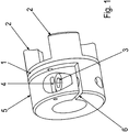
1 ist einerstes Kupplungsteil 1 eines ersten erfindungsgemäßen Ausführungsbeispiel dargestellt. - In
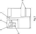
der 2 ist eine zur1 zugehörige Seitenansicht dargestellt. - In
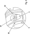
der 3 ist eine Schrägansicht eines vergrößerten Ausschnitts des ersten Kupplungsteils1 gezeigt. - In
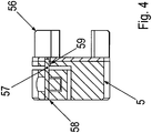
der 4 istdas erste Kupplungsteil 1 im Querschnitt dargestellt. - In
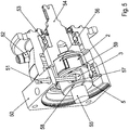
der 5 ist ein zwischen einem Motor und einem Getriebe anordenbarer Adapter mit einerdas erste Kupplungsteil 1 aufweisenden Klauenkupplung gezeigt.
- In the
1 is a first coupling part1 a first embodiment of the invention shown. - In the
2 is one to1 associated side view shown. - In the
3 is an oblique view of an enlarged section of thefirst coupling part 1 shown. - In the
4 is thefirst coupling part 1 shown in cross section. - In the
5 is an adapter which can be arranged between an engine and a transmission and has thefirst coupling part 1 having shown jaw clutch.
Wie in den
Das Kupplungsteil
Der Klemmbereich
Der Klemmbereich
Der Klemmbereich
Hierzu ist eine tangential gerichtete, durch den Schlitz
Vom Schlitz
Der Stift
Der Stift
Der Stift
Der Stift
Wie in
Der Stift
Der Stift
Der Stift
Allerdings reicht der Stift
Somit ist durch geeignete Positionierung und Dimensionierung des Langlochs
Mittels des Stiftes
Der Stift
Das maximale Klemmdrehmoment wäre bei Verschwinden der Schlitzweite erreicht. Um eine Beschädigung der Welle beim Einschrauben der Schraube
Wie oben gesagt, begrenzt das Langloch
Die Kupplung, umfassend das erste Klauenkupplungsteil
Die Ausnehmung überdeckt also denselben axialen Bereich und - zumindest bei geeigneter Drehstellung der Welle - denselben Umfangswinkelbereich wie der Schraubenkopf der Schraube
Die axiale Richtung ist parallel zur Drehachse der Welle ausgerichtet.The axial direction is aligned parallel to the axis of rotation of the shaft.
Das Langloch
Wie in
Das Gehäuseteil
Somit ist eine Entlüftung des teilweise mit Getriebeöl befüllten Innenraumes des Getriebes mittels der Entlüftungsschraube
Im Gehäuseteil
Die Adapterwelle
Die Schraube
Der Klauenbereich
BezugszeichenlisteLIST OF REFERENCE NUMBERS
- 11
- Kupplungsteil einer KlauenkupplungCoupling part of a dog clutch
- 22
- Klauenbereichclaw portion
- 33
- Schraubescrew
- 44
- Stift, axial gerichtetPin, directed axially
- 55
- Klemmbereichclamping range
- 66
- Schlitzslot
- 50 50
- Gehäuseteil, insbesondere AdaptergehäuseteilHousing part, in particular adapter housing part
- 5151
- SechskantwerkzeugHex tool
- 5252
- Entlüftungsschraubebleed screw
- 5353
- Lagerwarehouse
- 5454
- Adapterwelleadapter shaft
- 5555
- Motorwelle, RotorwelleMotor shaft, rotor shaft
- 5656
-
Klauenbereich der Adapterwelle
54 Claw area of theadapter shaft 54 - 5757
- Stiftpen
- 5858
- Rundlochround hole
- 5959
- LanglochLong hole
ZITATE ENTHALTEN IN DER BESCHREIBUNG QUOTES INCLUDE IN THE DESCRIPTION
Diese Liste der vom Anmelder aufgeführten Dokumente wurde automatisiert erzeugt und ist ausschließlich zur besseren Information des Lesers aufgenommen. Die Liste ist nicht Bestandteil der deutschen Patent- bzw. Gebrauchsmusteranmeldung. Das DPMA übernimmt keinerlei Haftung für etwaige Fehler oder Auslassungen.This list of the documents listed by the applicant has been generated automatically and is included solely for the better information of the reader. The list is not part of the German patent or utility model application. The DPMA assumes no liability for any errors or omissions.
Zitierte PatentliteraturCited patent literature
- DE 102011013887 A1 [0002]DE 102011013887 A1 [0002]
Claims (9)
Applications Claiming Priority (2)
| Application Number | Priority Date | Filing Date | Title |
|---|---|---|---|
| DE102018000947 | 2018-01-19 | ||
| DE102018000947.6 | 2018-01-19 |
Publications (1)
| Publication Number | Publication Date |
|---|---|
| DE102018009862A1 true DE102018009862A1 (en) | 2019-07-25 |
Family
ID=65199369
Family Applications (1)
| Application Number | Title | Priority Date | Filing Date |
|---|---|---|---|
| DE102018009862.2A Pending DE102018009862A1 (en) | 2018-01-19 | 2018-12-19 | Drive device, comprising at least one coupling and a shaft |
Country Status (4)
| Country | Link |
|---|---|
| EP (1) | EP3740690B1 (en) |
| CN (1) | CN111712646B (en) |
| DE (1) | DE102018009862A1 (en) |
| WO (1) | WO2019141342A1 (en) |
Cited By (1)
| Publication number | Priority date | Publication date | Assignee | Title |
|---|---|---|---|---|
| US20230391297A1 (en) * | 2020-02-18 | 2023-12-07 | Carroll Innovations, LLC | Motorized lifting system for semi-trailer |
Families Citing this family (2)
| Publication number | Priority date | Publication date | Assignee | Title |
|---|---|---|---|---|
| CN112253638A (en) * | 2020-12-18 | 2021-01-22 | 杭州景业智能科技股份有限公司 | Coupling structure capable of being rapidly assembled in nuclear industrial equipment |
| US12305744B2 (en) | 2021-07-28 | 2025-05-20 | Sew-Eurodrive Gmbh & Co. Kg | Adapter series for geared motors, and method for producing an adapter |
Citations (1)
| Publication number | Priority date | Publication date | Assignee | Title |
|---|---|---|---|---|
| DE102011013887A1 (en) | 2011-03-07 | 2012-09-13 | Stöber Antriebstechnik GmbH & Co. KG | Clamping coupling for non-rotatable connection of two rotating parts, preferably shaft and hub |
Family Cites Families (19)
| Publication number | Priority date | Publication date | Assignee | Title |
|---|---|---|---|---|
| US3935716A (en) * | 1972-05-11 | 1976-02-03 | Kupplungstechnik Gmbh | Shaft coupling |
| US4830297A (en) * | 1987-11-25 | 1989-05-16 | Statomat-Globe, Inc. | Winding form assembly |
| CH680303A5 (en) * | 1990-02-16 | 1992-07-31 | Syma Intercontinental Sa | |
| JP3177496B2 (en) * | 1998-04-13 | 2001-06-18 | 株式会社椿本チエイン | Rotating body fixture |
| DE29811026U1 (en) * | 1998-06-22 | 1998-09-03 | MECHANIK-Langewiesen e.G., 98704 Langewiesen | Connection system for pipes |
| DE20300724U1 (en) * | 2003-01-17 | 2003-05-08 | Ktr Kupplungstechnik Gmbh, 48432 Rheine | clamping hub |
| US7155145B2 (en) * | 2003-07-28 | 2006-12-26 | Konica Minolta Business Technologies, Inc. | Image Forming Apparatus Having Drive Section Coupled with Image Bearing Body |
| US7143988B2 (en) * | 2004-06-10 | 2006-12-05 | Diani, Llc. | Apparatus and method for mounting a fixture |
| CN200968362Y (en) * | 2006-07-28 | 2007-10-31 | 沈阳森德尔传动技术有限公司 | Couplings |
| CZ303995B6 (en) * | 2008-04-25 | 2013-08-07 | Sew Eurodrive Cz S. R. O. | Differential gear with balancing mechanism |
| JP2010133476A (en) * | 2008-12-04 | 2010-06-17 | Ricoh Co Ltd | Shaft coupling structure, unit for image forming device using the same, and image forming device using the unit |
| DE102009007557A1 (en) * | 2009-02-04 | 2010-08-05 | Sew-Eurodrive Gmbh & Co. Kg | Worm gear for suspension track drive, has actuating bolt movable by shift lever in axial direction, and driven gear connected with output shaft by actuator in detachable and form fit manner |
| BR112014010893A8 (en) * | 2011-11-07 | 2018-02-14 | Schaeffler Technologies Gmbh & Co Kg | CLUTCH DEVICE |
| DE102012013350C5 (en) * | 2012-07-06 | 2024-02-15 | Sew-Eurodrive Gmbh & Co Kg | Electromagnet, electromagnetically actuated brake and brake motor |
| CN103104626A (en) * | 2012-11-15 | 2013-05-15 | 福建雪人压缩机科技有限公司 | Adapter connecting spiral lobe compressor and motor |
| CN103603858B (en) * | 2013-11-28 | 2016-03-09 | 四川航天计量测试研究所 | A kind of miniature docking separating mechanism |
| WO2017094171A1 (en) * | 2015-12-03 | 2017-06-08 | 株式会社ハーモニック・ドライブ・システムズ | Shaft coupling |
| CN205823826U (en) * | 2016-06-24 | 2016-12-21 | 山东鲁滨逊体育用品有限公司 | Four joint walking stick external fibre reinforced retaining mechanisms |
| CN106328399B (en) * | 2016-09-29 | 2018-08-24 | 河南平高电气股份有限公司 | Folder is embraced in a kind of electric operating mechanism and its adjustment |
-
2018
- 2018-12-19 EP EP18839522.2A patent/EP3740690B1/en active Active
- 2018-12-19 DE DE102018009862.2A patent/DE102018009862A1/en active Pending
- 2018-12-19 WO PCT/EP2018/025327 patent/WO2019141342A1/en not_active Ceased
- 2018-12-19 CN CN201880085849.XA patent/CN111712646B/en active Active
Patent Citations (1)
| Publication number | Priority date | Publication date | Assignee | Title |
|---|---|---|---|---|
| DE102011013887A1 (en) | 2011-03-07 | 2012-09-13 | Stöber Antriebstechnik GmbH & Co. KG | Clamping coupling for non-rotatable connection of two rotating parts, preferably shaft and hub |
Cited By (1)
| Publication number | Priority date | Publication date | Assignee | Title |
|---|---|---|---|---|
| US20230391297A1 (en) * | 2020-02-18 | 2023-12-07 | Carroll Innovations, LLC | Motorized lifting system for semi-trailer |
Also Published As
| Publication number | Publication date |
|---|---|
| WO2019141342A8 (en) | 2020-08-13 |
| EP3740690B1 (en) | 2022-07-13 |
| CN111712646A (en) | 2020-09-25 |
| WO2019141342A1 (en) | 2019-07-25 |
| CN111712646B (en) | 2022-08-05 |
| EP3740690A1 (en) | 2020-11-25 |
Similar Documents
| Publication | Publication Date | Title |
|---|---|---|
| EP2241781B2 (en) | Gear, in particular planetary gear with a flange and a hollow wheel | |
| DE3119367C1 (en) | Device for the hydraulic actuation of a drawn friction clutch for motor vehicles | |
| DE102019003546A1 (en) | Adapter for a drive and drive | |
| DE102018009862A1 (en) | Drive device, comprising at least one coupling and a shaft | |
| EP2805078B1 (en) | Shaft-hub coupling, adapter and drive motor | |
| DE102008035185A1 (en) | fan clutch | |
| DE202010002926U1 (en) | Puller with counterholder | |
| DE102019206810A1 (en) | A holding arrangement for a circular saw tool | |
| EP3334949B1 (en) | Connection assembly of a transmission in a structure | |
| DE102018009861A1 (en) | Drive device, comprising at least one coupling and a shaft | |
| DE102010053055A1 (en) | Device for fastening fan to drive shaft of motor vehicle, has holding lugs spaced in circumferential direction and passing through three openings, which are formed through lugs of fan to obtain bayonet-fastening | |
| EP3538782B1 (en) | Gear motor comprising a gear mechanism driven by an electric motor | |
| DE102014224064A1 (en) | The torque transfer device | |
| DE102017204114A1 (en) | Drive unit for an actuator, as well as actuator with a drive unit and a gear unit | |
| DE102014005415A1 (en) | Bearing arrangement, in particular for a transmission, and method for adjusting the preload of a bearing assembly | |
| DE102017009864A1 (en) | Geared motor comprising a gear driven by an electric motor | |
| DE102017200411A1 (en) | Mounting arrangement for fastening at least one component on a shaft | |
| DE3047256A1 (en) | Motor vehicle friction clutch - has pre-loaded U=section springs joining housing to pressure plate | |
| DE10314219A1 (en) | Overload clutch | |
| EP1795754A2 (en) | Universal flange | |
| DE3940982A1 (en) | IC engine clutch mfr. - involves tool with centring part to assemble clutch plate on flywheel | |
| DE102017009919A1 (en) | Transmission with a first housing part and a second housing part | |
| DE102011104058A1 (en) | Connecting arrangement between a propeller shaft and a transmission | |
| DE102019000421A1 (en) | Method for clamping a hollow shaft area with a shaft by means of a clamping ring and arrangement for carrying out the method | |
| DE102015223756A1 (en) | Centering pin for a plate spring of a friction clutch |
Legal Events
| Date | Code | Title | Description |
|---|---|---|---|
| R012 | Request for examination validly filed |