DE102018009861A1 - Drive device, comprising at least one coupling and a shaft - Google Patents
Drive device, comprising at least one coupling and a shaft Download PDFInfo
- Publication number
- DE102018009861A1 DE102018009861A1 DE102018009861.4A DE102018009861A DE102018009861A1 DE 102018009861 A1 DE102018009861 A1 DE 102018009861A1 DE 102018009861 A DE102018009861 A DE 102018009861A DE 102018009861 A1 DE102018009861 A1 DE 102018009861A1
- Authority
- DE
- Germany
- Prior art keywords
- screw
- drive device
- clamping
- coupling
- slot
- Prior art date
- Legal status (The legal status is an assumption and is not a legal conclusion. Google has not performed a legal analysis and makes no representation as to the accuracy of the status listed.)
- Pending
Links
Images
Classifications
-
- F—MECHANICAL ENGINEERING; LIGHTING; HEATING; WEAPONS; BLASTING
- F16—ENGINEERING ELEMENTS AND UNITS; GENERAL MEASURES FOR PRODUCING AND MAINTAINING EFFECTIVE FUNCTIONING OF MACHINES OR INSTALLATIONS; THERMAL INSULATION IN GENERAL
- F16D—COUPLINGS FOR TRANSMITTING ROTATION; CLUTCHES; BRAKES
- F16D1/00—Couplings for rigidly connecting two coaxial shafts or other movable machine elements
- F16D1/06—Couplings for rigidly connecting two coaxial shafts or other movable machine elements for attachment of a member on a shaft or on a shaft-end
- F16D1/08—Couplings for rigidly connecting two coaxial shafts or other movable machine elements for attachment of a member on a shaft or on a shaft-end with clamping hub; with hub and longitudinal key
- F16D1/0852—Couplings for rigidly connecting two coaxial shafts or other movable machine elements for attachment of a member on a shaft or on a shaft-end with clamping hub; with hub and longitudinal key with radial clamping between the mating surfaces of the hub and shaft
- F16D1/0864—Couplings for rigidly connecting two coaxial shafts or other movable machine elements for attachment of a member on a shaft or on a shaft-end with clamping hub; with hub and longitudinal key with radial clamping between the mating surfaces of the hub and shaft due to tangential loading of the hub, e.g. a split hub
-
- F—MECHANICAL ENGINEERING; LIGHTING; HEATING; WEAPONS; BLASTING
- F16—ENGINEERING ELEMENTS AND UNITS; GENERAL MEASURES FOR PRODUCING AND MAINTAINING EFFECTIVE FUNCTIONING OF MACHINES OR INSTALLATIONS; THERMAL INSULATION IN GENERAL
- F16D—COUPLINGS FOR TRANSMITTING ROTATION; CLUTCHES; BRAKES
- F16D3/00—Yielding couplings, i.e. with means permitting movement between the connected parts during the drive
- F16D3/84—Shrouds, e.g. casings, covers; Sealing means specially adapted therefor
- F16D3/843—Shrouds, e.g. casings, covers; Sealing means specially adapted therefor enclosed covers
-
- F—MECHANICAL ENGINEERING; LIGHTING; HEATING; WEAPONS; BLASTING
- F16—ENGINEERING ELEMENTS AND UNITS; GENERAL MEASURES FOR PRODUCING AND MAINTAINING EFFECTIVE FUNCTIONING OF MACHINES OR INSTALLATIONS; THERMAL INSULATION IN GENERAL
- F16D—COUPLINGS FOR TRANSMITTING ROTATION; CLUTCHES; BRAKES
- F16D3/00—Yielding couplings, i.e. with means permitting movement between the connected parts during the drive
- F16D3/50—Yielding couplings, i.e. with means permitting movement between the connected parts during the drive with the coupling parts connected by one or more intermediate members
- F16D3/64—Yielding couplings, i.e. with means permitting movement between the connected parts during the drive with the coupling parts connected by one or more intermediate members comprising elastic elements arranged between substantially-radial walls of both coupling parts
- F16D3/68—Yielding couplings, i.e. with means permitting movement between the connected parts during the drive with the coupling parts connected by one or more intermediate members comprising elastic elements arranged between substantially-radial walls of both coupling parts the elements being made of rubber or similar material
Landscapes
- Engineering & Computer Science (AREA)
- General Engineering & Computer Science (AREA)
- Mechanical Engineering (AREA)
- Clamps And Clips (AREA)
- Mechanical Operated Clutches (AREA)
- Details Of Spanners, Wrenches, And Screw Drivers And Accessories (AREA)
Abstract
Antriebsvorrichtung, aufweisend zumindest eine Kupplung und eine Welle,wobei die Kupplung als Klauenkupplung ausgeführt ist,wobei in der Kupplung ein Klemmbereich zur Klemmverbindung mit der Welle integriert ist,wobei der Klemmbereich mittels einer Schraube betätigbar ist,wobei der beim Betätigen der Schraube überdeckte Raumbereich mittels eines in eine Ausnehmung des Klemmbereichs zumindest teilweise eingeführten Stiftes in Schraubachsrichtung der Schraube begrenzt ist,insbesondere wobei der Stift tangential oder axial ausgerichtet ist.Drive device, comprising at least one coupling and a shaft, wherein the coupling is designed as a dog clutch, wherein in the coupling, a clamping area for clamping connection with the shaft is integrated, wherein the clamping area is actuated by a screw, wherein the space covered by pressing the screw space by means of a pin which is at least partially inserted into a recess of the clamping region is delimited in the screw axis direction of the screw, in particular wherein the pin is oriented tangentially or axially.
Description
Die Erfindung betrifft eine Antriebsvorrichtung, aufweisend zumindest eine Kupplung und eine Welle.The invention relates to a drive device, comprising at least one coupling and a shaft.
Als kraftschlüssige Verbindung ist aus der
Der Erfindung liegt daher die Aufgabe zugrunde, eine Klemmkupplung einer Antriebsvorrichtung weiterzubilden.The invention is therefore the object of developing a clamping coupling a drive device.
Erfindungsgemäß wird die Aufgabe bei der Antriebsvorrichtung nach den in Anspruch 1 oder 2 angegebenen Merkmalen gelöst.According to the invention the object is achieved in the drive device according to the features specified in
Wichtige Merkmale der Erfindung bei der Antriebsvorrichtung nach Anspruch 1 sind, dass die Antriebsvorrichtung zumindest eine Kupplung und eine Welle aufweist,
wobei die Kupplung als Klauenkupplung ausgeführt ist,
wobei in der Kupplung ein Klemmbereich zur Klemmverbindung mit der Welle integriert ist,
wobei der Klemmbereich mittels einer Schraube betätigbar ist,
wobei der beim Betätigen der Schraube überdeckte Raumbereich mittels eines in eine Ausnehmung des Klemmbereichs zumindest teilweise eingeführten Stiftes in Schraubachsrichtung der Schraube begrenzt ist,
insbesondere wobei der Stift tangential oder axial ausgerichtet ist.Important features of the invention in the drive device according to
wherein the coupling is designed as a dog clutch,
wherein in the coupling a clamping area is integrated for clamping connection with the shaft,
wherein the clamping region is actuated by means of a screw,
wherein the space area covered when the screw is actuated is limited in the screw axis direction of the screw by means of a pin which is at least partially inserted into a recess of the clamping area,
in particular, wherein the pin is aligned tangentially or axially.
Von Vorteil ist dabei, dass eine Begrenzung der Schlitzweite erreichbar ist und somit beim Herausschrauben der Schraube deren Schraubenkopf am Stift anliegt und daher der Klemmbereich aufgeweitet wird. Dies erfolgt sogar bei vorhandener Korrosion mit geringem Kraftaufwand.The advantage here is that a limitation of the slot width is reached and thus when unscrewing the screw whose screw head bears against the pin and therefore the clamping area is widened. This is done even with existing corrosion with little effort.
Wichtige Merkmale der Erfindung bei der Antriebsvorrichtung nach Anspruch 2 sind, dass die Antriebsvorrichtung zumindest eine Kupplung und eine Welle aufweist,
wobei die Kupplung ein erstes Kupplungsteil und ein weiteres Kupplungsteil aufweist,
wobei das erste Kupplungsteil einen Grundbereich aufweist, an welchem axial hervorstehende Klauen angeformt sind und auf der axial von den Klauenbereichen abgewandten Seite des Grundbereichs ein Klemmbereich zur kraftschlüssigen Verbindung der Welle mit dem ersten Kupplungsteil angeordnet ist,
wobei der Klemmbereich einen durchgehenden Schlitz, insbesondere einen axial und radial durch den Klemmbereich durchgehenden Schlitz, aufweist, durch welchen eine durch den Klemmbereich insbesondere tangential gerichtete Stufenbohrung ausgeführt ist,
wobei die Stufenbohrung auf der von der Stufe abgewandten Seite des Schlitzes einen Gewindeabschnitt aufweist, in welchen eine Schraube zumindest teilweise eingeschraubt ist,
wobei ein Stift in den Klemmbereich zumindest teilweise eingesteckt ist, welcher die Schraube begrenzt.Important features of the invention in the drive device according to
the coupling having a first coupling part and a further coupling part,
wherein the first coupling part has a base region, on which axially protruding claws are formed, and on the side of the base region, which faces away axially from the claw regions, a clamping region is arranged for non-positive connection of the shaft to the first coupling part,
wherein the clamping region has a continuous slot, in particular a slot extending axially and radially through the clamping region, through which a stepped bore, in particular tangentially directed through the clamping region, is implemented,
wherein the stepped bore on the side facing away from the step of the slot has a threaded portion in which a screw is at least partially screwed,
wherein a pin is at least partially inserted into the clamping area, which limits the screw.
Von Vorteil ist dabei, dass eine Begrenzung der Schlitzweite erreichbar ist und somit beim Herausschrauben der Schraube deren Schraubenkopf am Stift anliegt und daher der Klemmbereich aufgeweitet wird. Dies erfolgt sogar bei vorhandener <Korrosion mit geringem Kraftaufwand.The advantage here is that a limitation of the slot width is reached and thus when unscrewing the screw whose screw head bears against the pin and therefore the clamping area is widened. This is done even with existing <corrosion with little effort.
Bei einer vorteilhaften Ausgestaltung ist der Stift tangential ausgerichtet ist und nur einseitig im Klemmbereich aufgenommen. Von Vorteil ist dabei, dass die Montage aus tangentialer Richtung ausführbar ist, also auch wenn schon der Motor mit dem Adapter verbunden ist.In an advantageous embodiment, the pin is tangentially aligned and received only on one side in the clamping area. The advantage here is that the assembly from tangential direction is executable, so even if the engine is already connected to the adapter.
Bei einer vorteilhaften Ausgestaltung ist der Stift axial ausgerichtet ist und beidseitig im Klemmbereich aufgenommen. Von Vorteil ist dabei, dass der Stift sehr stabil aufgenommen ist im Klemmbereich. Außerdem ist die Montage bei noch nicht verbundenem Motor sehr einfach ausführbar.In an advantageous embodiment, the pin is axially aligned and received on both sides in the clamping area. The advantage here is that the pin is very stable recorded in the terminal area. In addition, the assembly is very simple executable when not connected engine.
Bei einer vorteilhaften Ausgestaltung sind der Stift und das erste Kupplungsteil beide aus Stahl oder beide aus Aluminium gefertigt. Von Vorteil ist dabei, dass eine vorteilhafte Materialpaarung erreichbar ist.In an advantageous embodiment of the pin and the first coupling part are both made of steel or both made of aluminum. The advantage here is that an advantageous combination of materials can be achieved.
Bei einer vorteilhaften Ausgestaltung ist der Stift tangential oder axial ausgerichtet. Von Vorteil ist dabei, dass eine einfache Herstellung ermöglicht ist.In an advantageous embodiment, the pin is aligned tangentially or axially. The advantage here is that a simple production is possible.
Bei einer vorteilhaften Ausgestaltung ist der Stift tangential ausgerichtet und in eine tangential gerichtete Bohrung des Klemmbereichs eingesteckt und pressverbunden. Von Vorteil ist dabei, dass eine einfache Herstellung ermöglicht ist und ein Austauschen des Stiftes sogar von der Umgebung her kommend durch eine Ausnehmung des Gehäuses ausführbar ist.In an advantageous embodiment, the pin is aligned tangentially and inserted into a tangentially directed bore of the clamping area and press-connected. The advantage here is that a simple production is made possible and replacement of the pin even from the environment coming through a recess of the housing is executable.
Bei einer vorteilhaften Ausgestaltung ist der Stift axial ausgerichtet und beidseitig im Klemmbereich aufgenommen, wobei er in einer ersten axial gerichteten Bohrung des Klemmbereichs zumindest teilweise aufgenommen ist und wobei er in einer zweiten, axial gerichteten Bohrung zumindest teilweise aufgenommen ist,
wobei die erste Bohrung durch den Klemmbereich durchgehend ausgeführt ist, insbesondere in den Raumbereich der Stufenbohrung mündend ausgeführt ist,
wobei die zweite Bohrung als Sacklochbohrung im Klemmbereich ausgeführt ist, insbesondere in den Raumbereich der Stufenbohrung mündend ausgeführt ist. Von Vorteil ist dabei, dass der Stift stabil gelagert ist. Insbesondere ist er an zumindest zwei Punkten gelagert. Wenn die zweite Bohrung als durchgehende Bohrung und nicht als Sacklochbohrung ausgeführt wird, ist beim Einstecken des Stiftes in die zweite Bohrung keine entgegenwirkende Luftpressung vorhanden, so dass die notwendige Fügekraft verringert ist.In an advantageous embodiment, the pin is axially aligned and received on both sides in the clamping area, wherein it is at least partially received in a first axially directed bore of the clamping area and wherein it is at least partially received in a second, axially directed bore,
wherein the first bore is executed continuously through the clamping region, in particular is designed to open into the spatial region of the stepped bore,
wherein the second bore is designed as a blind hole in the clamping area, in particular in the space area of the stepped bore is made opening. The advantage here is that the pin is stored stable. In particular, it is stored at at least two points. If the second bore is designed as a through hole and not as a blind hole, no counteracting air pressure is present when inserting the pin in the second bore, so that the necessary joining force is reduced.
Bei einer vorteilhaften Ausgestaltung ist ein Begrenzungsteil beidseitig des Schlitzes mit dem Klemmbereich formschlüssig verbunden,
insbesondere wobei das Begrenzungsteil auf der der Stufe zugewandten Seite des Schlitzes mit dem Klemmbereich spielfrei verbunden ist,
insbesondere wobei das Begrenzungsteil auf der der Stufe abgewandten Seite des Schlitzes mit dem Klemmbereich spielbehaftet verbunden ist, insbesondere zur Begrenzung der Schlitzweite beim Betätigen der Schraube auf einen maximalen Wert. Von Vorteil ist dabei, dass eine erhöhte Sicherheit gewährleistbar ist. Insbesondere ist eine spielfreie Verbindung erreichbar und somit ein Klappern bei Betrieb, insbesondere bei umrichtergespeistem Elektromotor zum Antrieben der Welle, vermeidbar.In an advantageous embodiment, a boundary part on both sides of the slot is positively connected to the clamping area,
in particular, wherein the limiting part is connected without play on the side of the slot facing the step, with the clamping area,
in particular wherein the limiting part is connected on the side facing away from the step of the slot with the clamping area with play, in particular for limiting the slot width when operating the screw to a maximum value. The advantage here is that increased security can be ensured. In particular, a backlash-free connection can be achieved and thus rattling during operation, in particular in the case of a converter-fed electric motor for driving the shaft, can be avoided.
Weiter ist von Vorteil, dass mittels des Begrenzungsteils der Aufspreizweg des Klemmbereichs limitierbar ist. Auf diese Weise ist das Material der Kupplungsteile vor Überlastung geschützt, insbesondere ist auch die Schraube und der Gewindebereich vor Überlastung geschützt. Außerdem erspürt der Anwender beim Betätigen der Klemmverbindung, wann die Aufspreizung ausreichend ist.It is furthermore advantageous that the spreading path of the clamping region can be limited by means of the delimiting part. In this way, the material of the coupling parts is protected from overloading, in particular, the screw and the threaded portion is protected from overloading. In addition, the user senses when pressing the clamp connection, when the spread is sufficient.
Bei einer vorteilhaften Ausgestaltung ist das Begrenzungsteil einstückig, insbesondere einteilig, mit dem Klemmbereich ausgeformt. Von Vorteil ist dabei, dass eine einfache Herstellung ermöglicht ist.In an advantageous embodiment, the limiting part is in one piece, in particular in one piece, formed with the clamping area. The advantage here is that a simple production is possible.
Bei einer vorteilhaften Ausgestaltung weist das Begrenzungsteil eine Verdickung, insbesondere eine in den Schlitz hineinragende Verdickung, auf, insbesondere zur Begrenzung der Schlitzweite auf einen minimalen, nicht verschwindenden Wert beim Betätigen der Schraube. Von Vorteil ist dabei, dass die Klemmkraft oder besser das Klemmmoment auf einen maximalen Wert begrenzbar ist und somit empfindliche Wellen, insbesondere Vollwellen oder Hohlwellen, geschützt verbindbar sind.In an advantageous embodiment, the limiting part has a thickening, in particular a thickening projecting into the slot, in particular for limiting the slot width to a minimum, non-vanishing value when the screw is actuated. The advantage here is that the clamping force or better the clamping torque can be limited to a maximum value and thus sensitive waves, in particular solid waves or hollow shafts, are protected connected.
Bei einer vorteilhaften Ausgestaltung ist das Begrenzungsteil aus axialer Richtung kommend in den Klemmbereich eingeschoben. Von Vorteil ist dabei, dass eine einfache Herstellung ermöglicht ist.In an advantageous embodiment, the boundary part is inserted from the axial direction coming into the clamping area. The advantage here is that a simple production is possible.
Bei einer vorteilhaften Ausgestaltung weist das Begrenzungsteil auf seiner von der Stufe abgewandten Seite eine Kunststoffbeschichtung auf. Von Vorteil ist dabei, dass zwar ein Spiel zwischen dem metallischen Material des Begrenzungsteils und dem metallischen Material des Klemmbereichs vorhanden ist, aber aufeinander schlagende Berührungen zwischen Begrenzungsteil und Klemmbereich vermeidbar sind. Der Hinterschnitt ist beispielsweise herstellbar durch Erodieren oder dergleichen.In an advantageous embodiment, the boundary part on its side facing away from the step side on a plastic coating. The advantage here is that although there is a match between the metallic material of the delimiting portion and the metallic material of the clamping area, but successive beating between boundary part and clamping area can be avoided. The undercut can be produced, for example, by eroding or the like.
Bei einer vorteilhaften Ausgestaltung ist das Begrenzungsteil mit dem Klemmbereich auf der der Stufe zugewandten Seite des Schlitzes einstückig, also einteilig, ausgeführt,
insbesondere wobei das Begrenzungsteil auf der der Stufe abgewandten Seite des Schlitzes mit dem Klemmbereich spielbehaftet verbunden ist, insbesondere zur Begrenzung der Schlitzweite beim Betätigen der Schraube auf einen maximalen Wert. Von Vorteil ist dabei, dass das Begrenzungsteil einstückig mit dem Klemmbereich ausgeführt ist und somit kein Verschließ der Verbindung auftreten kann. Außerdem ist nur auf der von der Stifte abgewandten Seite des Schlitzes im Klemmbereich ein Hinterschnitt auszuführen, in welchen das Begrenzungsteil hineinragt. Auf diese Weise ist ein einfaches Herstellen der Begrenzung der Schlitzweite ausführbar.In an advantageous embodiment, the limiting part with the clamping area on the side facing the step of the slot is in one piece, so one piece, executed,
in particular wherein the limiting part is connected on the side facing away from the step of the slot with the clamping area with play, in particular for limiting the slot width when operating the screw to a maximum value. The advantage here is that the limiting part is made in one piece with the clamping area and thus no closure of the connection can occur. In addition, only on the side facing away from the pins of the slot in the clamping area to perform an undercut into which projects the boundary part. In this way, a simple production of the limitation of the slot width is executable.
Bei einer vorteilhaften Ausgestaltung weist die Antriebsvorrichtung einen Elektromotor auf, dessen Welle mittels der Kupplung mit der eintreibenden Welle eines Getriebes der Antriebsvorrichtung verbunden ist,In an advantageous embodiment, the drive device has an electric motor whose shaft is connected by means of the coupling with the input shaft of a transmission of the drive device,
Bei einer vorteilhaften Ausgestaltung ist die Kupplung in einem Adaptergehäuse angeordnet, welches eine durchgehende Ausnehmung aufweist, welche den von der Schraube überdeckten axialen Bereich überdeckt.In an advantageous embodiment, the coupling is arranged in an adapter housing, which has a continuous recess which covers the axial area covered by the screw.
Bei einer vorteilhaften Ausgestaltung weist die Antriebsvorrichtung einen Elektromotor auf, dessen Welle mittels der Kupplung mit der eintreibenden Welle eines Getriebes der Antriebsvorrichtung verbunden ist,
wobei die Kupplung in einem Adaptergehäuse, insbesondere Gehäuseteil, angeordnet ist, welches eine durchgehende Ausnehmung aufweist, welche den von der Schraube überdeckten axialen Bereich überdeckt, insbesondere so dass ein Werkzeug zum Betätigen der Schraube durch die durchgehende Ausnehmung durchführbar ist. Von Vorteil ist dabei, dass zur Herstellung das Getriebe zunächst mit dem Adapter verbunden wird, also die Adapterwelle samt verbundenem Verzahnungsteil ins Getriebe eingeschoben wird. Axial neben dem Lager der Adapterwelle ist im Adapter ein Wellendichtring angeordnet. Auf diese Weise ist das Getriebeöl des Innenraums des Getriebes ferngehalten vom Innenraum des Adapters, also auch von dem die Klauenkupplung aufnehmenden Innenraumbereich des Adapters. Nach Verbinden des Adapters mit dem Getriebe ist somit der Motor an den Adapter anschraubbar,
wobei die Motorwelle in den Klemmbereich der Kupplung des Adapters eingesteckt wird. Die Betätigung der Klemmverbindung ist dann durch die durchgehende Ausnehmung hindurch ermöglicht.In an advantageous embodiment, the drive device has an electric motor whose shaft is connected by means of the coupling with the input shaft of a transmission of the drive device,
wherein the coupling is arranged in an adapter housing, in particular a housing part, which has a continuous recess which covers the axial area covered by the screw, in particular so that a tool for actuating the screw can be passed through the continuous recess. The advantage here is that for the preparation of the transmission is first connected to the adapter, so the adapter shaft is inserted together with the connected gear part in the transmission. Axial next to the bearing of the adapter shaft a shaft seal is arranged in the adapter. In this way, the transmission oil of the interior of the transmission is kept away from the interior of the adapter, ie also from the claw clutch receiving interior space of the adapter. After connecting the adapter to the transmission, the motor can thus be screwed to the adapter,
wherein the motor shaft is inserted into the clamping region of the coupling of the adapter. The actuation of the clamping connection is then made possible by the continuous recess.
Bei einer vorteilhaften Ausgestaltung ist das Adaptergehäuse, insbesondere das Gehäuseteil, schraubverbunden mit einem Gehäuseteil des Elektromotors und mit einem Gehäuseteil des Getriebes,
wobei das Adaptergehäuse einen Kanal aufweist, welcher in den Innenraum des Getriebes oder in eine durch das Gehäuseteil des Getriebes durchgehende Ausnehmung mündet,
wobei der Kanal zur Umgebung hin mit einer Entlüftungsschraube, insbesondere mit einer eine semipermeable Membran aufweisenden Entlüftungsschraube, verschlossen ist, insbesondere derart, dass ein Luftdruckausgleich vom Innenraum des Getriebes zur Umgebung hin erfolgt, aber kein Austritt von Getriebeöl. Von Vorteil ist dabei, dass die Entlüftung des Getriebes über den Adapter ausgeführt wird. Somit muss im Getriebegehäuse keine durchgehende Ausnehmung vorgesehen werden.In an advantageous embodiment, the adapter housing, in particular the housing part, is screw-connected to a housing part of the electric motor and to a housing part of the transmission,
wherein the adapter housing has a channel which opens into the interior of the transmission or into a through-going through the housing part of the transmission recess,
wherein the channel is closed to the environment with a vent screw, in particular with a semipermeable membrane having vent screw, in particular such that an air pressure equalization takes place from the interior of the transmission to the environment, but no leakage of transmission oil. The advantage here is that the venting of the transmission is performed via the adapter. Thus, no continuous recess must be provided in the transmission housing.
Weitere Vorteile ergeben sich aus den Unteransprüchen. Die Erfindung ist nicht auf die Merkmalskombination der Ansprüche beschränkt. Für den Fachmann ergeben sich weitere sinnvolle Kombinationsmöglichkeiten von Ansprüchen und/oder einzelnen Anspruchsmerkmalen und/oder Merkmalen der Beschreibung und/oder der Figuren, insbesondere aus der Aufgabenstellung und/oder der sich durch Vergleich mit dem Stand der Technik stellenden Aufgabe.Further advantages emerge from the subclaims. The invention is not limited to the combination of features of the claims. For the skilled person, further meaningful combination possibilities of claims and / or individual claim features and / or features of the description and / or figures, in particular from the task and / or posing by comparison with the prior art task arise.
Die Erfindung wird nun anhand von schematischen Abbildungen näher erläutert:
- In
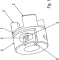
der 1 istein erstes Kupplungsteil 1 eines ersten erfindungsgemäßen Ausführungsbeispiel dargestellt. - In
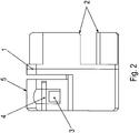
der 2 ist eine zur1 zugehörige Seitenansicht dargestellt. - In
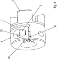
der 3 ein Kupplungsteil 1 eines zweiten erfindungsgemäßen Ausführungsbeispiel gezeigt,wobei ein Begrenzungsteil 30 vorgesehen ist. - In
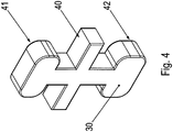
der 4 ist das Begrenzungsteil 30 in Schrägansicht dargestellt. - In
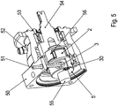
der 5 ist ein zwischen einem Motor und einem Getriebe anordenbarer Adapter mit einerdas erste Kupplungsteil 1 aufweisenden Klauenkupplung gezeigt.
- In the
1 is a first coupling part1 a first embodiment of the invention shown. - In the
2 is one to1 associated side view shown. - In the
3 a coupling part1 a second embodiment of the invention shown, wherein a limitingpart 30 is provided. - In the
4 is thelimit part 30 shown in an oblique view. - In the
5 is an adapter which can be arranged between an engine and a transmission and has thefirst coupling part 1 having shown jaw clutch.
Wie in den
Das Kupplungsteil
Der Klemmbereich
Der Klemmbereich
Der Klemmbereich
Hierzu ist eine tangential gerichtete, durch den Schlitz
Vom Schlitz
Der Stift
Der Stift
Der Stift
Der Stift
Wie in
Der Stift
Der Stift
Das maximale Klemmdrehmoment wäre bei Verschwinden der Schlitzweite erreicht. Um eine Beschädigung der Welle beim Einschrauben der Schraube
Dieses Begrenzungsteil
Hierzu ist das Begrenzungsteil
Hierbei ist die erste Vertiefung in tangentialer Richtung vom Schlitz
Die beiden aufgeweiteten Bereiche des Begrenzungsteils
Das Begrenzungsteil
In der zweiten Vertiefung ist zwischen Klemmbereich
Vorzugsweise ist auf an der vom Schraubenkopf abgewandten Oberfläche des Begrenzungsteils
Das Begrenzungsteil
Die Kupplung, umfassend das erste Klauenkupplungsteil
Die Ausnehmung überdeckt also denselben axialen Bereich und - zumindest bei geeigneter Drehstellung der Welle - denselben Umfangswinkelbereich wie der Schraubenkopf der Schraube
Vorzugsweise ist das Begrenzungsteil
Wie in
Die axiale Richtung ist parallel zur Drehachse der Welle ausgerichtet.The axial direction is aligned parallel to the axis of rotation of the shaft.
Bei weiteren erfindungsgemäßen Ausführungsbeispielen wird das Begrenzungsteil
Vorzugsweise ist auch eine andere Formgebung ermöglicht, wobei wichtig ist, dass eine am dem Schraubenkopf zugewandten Bereich des Klemmbereichs
Wie in
Das Gehäuseteil
Somit ist eine Entlüftung des teilweise mit Getriebeöl befüllten Innenraumes des Getriebes mittels der Entlüftungsschraube
Im Gehäuseteil
Die Adapterwelle
Die Schraube
Der Klauenbereich
BezugszeichenlisteLIST OF REFERENCE NUMBERS
- 11
- Kupplungsteil einer KlauenkupplungCoupling part of a dog clutch
- 22
- Klauenbereichclaw portion
- 33
- Schraubescrew
- 44
- Stift, axial gerichtetPin, directed axially
- 55
- Klemmbereichclamping range
- 66
- Schlitzslot
- 3030
- Begrenzungsteillimiting member
- 3131
- Schlitzslot
- 3232
- Stift, tangential gerichtetPen, directed tangentially
- 4040
- Verdickungthickening
- 4141
- Aufweitungwidening
- 4242
- Aufweitungwidening
- 5050
- Gehäuseteil, insbesondere AdaptergehäuseteilHousing part, in particular adapter housing part
- 5151
- SechskantwerkzeugHex tool
- 5252
- Entlüftungsschraubebleed screw
- 5353
- Lagerwarehouse
- 54 54
- Adapterwelleadapter shaft
- 5555
- Motorwelle, RotorwelleMotor shaft, rotor shaft
- 5656
-
Klauenbereich der Adapterwelle 54Claw area of the
adapter shaft 54
ZITATE ENTHALTEN IN DER BESCHREIBUNG QUOTES INCLUDE IN THE DESCRIPTION
Diese Liste der vom Anmelder aufgeführten Dokumente wurde automatisiert erzeugt und ist ausschließlich zur besseren Information des Lesers aufgenommen. Die Liste ist nicht Bestandteil der deutschen Patent- bzw. Gebrauchsmusteranmeldung. Das DPMA übernimmt keinerlei Haftung für etwaige Fehler oder Auslassungen.This list of the documents listed by the applicant has been generated automatically and is included solely for the better information of the reader. The list is not part of the German patent or utility model application. The DPMA assumes no liability for any errors or omissions.
Zitierte PatentliteraturCited patent literature
- DE 102011013887 A1 [0002]DE 102011013887 A1 [0002]
Claims (15)
Applications Claiming Priority (2)
| Application Number | Priority Date | Filing Date | Title |
|---|---|---|---|
| DE102018000439 | 2018-01-19 | ||
| DE102018000439.3 | 2018-01-19 |
Publications (1)
| Publication Number | Publication Date |
|---|---|
| DE102018009861A1 true DE102018009861A1 (en) | 2019-07-25 |
Family
ID=65199368
Family Applications (1)
| Application Number | Title | Priority Date | Filing Date |
|---|---|---|---|
| DE102018009861.4A Pending DE102018009861A1 (en) | 2018-01-19 | 2018-12-19 | Drive device, comprising at least one coupling and a shaft |
Country Status (4)
| Country | Link |
|---|---|
| EP (1) | EP3740689B1 (en) |
| CN (1) | CN111566370B (en) |
| DE (1) | DE102018009861A1 (en) |
| WO (1) | WO2019141341A1 (en) |
Families Citing this family (2)
| Publication number | Priority date | Publication date | Assignee | Title |
|---|---|---|---|---|
| CN112253638A (en) * | 2020-12-18 | 2021-01-22 | 杭州景业智能科技股份有限公司 | Coupling structure capable of being rapidly assembled in nuclear industrial equipment |
| KR102833572B1 (en) * | 2025-02-25 | 2025-07-14 | 주식회사 화인솔루션 | Shaft Joint with foreign matter adhesion prevention |
Citations (1)
| Publication number | Priority date | Publication date | Assignee | Title |
|---|---|---|---|---|
| DE102011013887A1 (en) | 2011-03-07 | 2012-09-13 | Stöber Antriebstechnik GmbH & Co. KG | Clamping coupling for non-rotatable connection of two rotating parts, preferably shaft and hub |
Family Cites Families (16)
| Publication number | Priority date | Publication date | Assignee | Title |
|---|---|---|---|---|
| US4416563A (en) * | 1982-03-29 | 1983-11-22 | Bell & Howell Company | Shaft coupling device |
| JPS60252822A (en) * | 1984-05-25 | 1985-12-13 | Koyo Seiko Co Ltd | Coupling device for shaft or similar member |
| JPH0830502B2 (en) * | 1987-08-04 | 1996-03-27 | 三木プ−リ株式会社 | Hub / shaft fixing device |
| US4830297A (en) * | 1987-11-25 | 1989-05-16 | Statomat-Globe, Inc. | Winding form assembly |
| DE19625580C2 (en) * | 1996-06-27 | 2000-07-06 | Ifm Electronic Gmbh | Adjustment device for attaching and adjusting a part |
| DE19716632A1 (en) * | 1997-04-21 | 1998-10-22 | Fischer Artur Werke Gmbh | Pipe clamp |
| JP3177496B2 (en) * | 1998-04-13 | 2001-06-18 | 株式会社椿本チエイン | Rotating body fixture |
| SE518695C2 (en) * | 2001-03-22 | 2002-11-05 | Rolls Royce Ab | Shaft coupling and shaft joint with a first shaft part, a second shaft part and a shaft coupling |
| DE20300724U1 (en) * | 2003-01-17 | 2003-05-08 | Ktr Kupplungstechnik Gmbh, 48432 Rheine | clamping hub |
| CN200968362Y (en) * | 2006-07-28 | 2007-10-31 | 沈阳森德尔传动技术有限公司 | Couplings |
| ES2371908T3 (en) * | 2007-05-14 | 2012-01-11 | Delaware Capital Formation, Inc. | TELESCOPIC FIXING ASSEMBLY. |
| CN103775516A (en) * | 2012-10-28 | 2014-05-07 | 山东双轮股份有限公司 | Clamping shell coupler |
| DE102015003468B4 (en) * | 2015-03-19 | 2016-09-29 | Sew-Eurodrive Gmbh & Co Kg | electric motor |
| JP2017036806A (en) * | 2015-08-11 | 2017-02-16 | 株式会社ツバキE&M | Shaft coupling |
| WO2017094171A1 (en) * | 2015-12-03 | 2017-06-08 | 株式会社ハーモニック・ドライブ・システムズ | Shaft coupling |
| CN106640995B (en) * | 2016-12-29 | 2018-11-09 | 日本电产新宝(浙江)有限公司 | Clamp system and equipment with the clamp system |
-
2018
- 2018-12-19 DE DE102018009861.4A patent/DE102018009861A1/en active Pending
- 2018-12-19 CN CN201880085882.2A patent/CN111566370B/en active Active
- 2018-12-19 WO PCT/EP2018/025326 patent/WO2019141341A1/en not_active Ceased
- 2018-12-19 EP EP18839521.4A patent/EP3740689B1/en active Active
Patent Citations (1)
| Publication number | Priority date | Publication date | Assignee | Title |
|---|---|---|---|---|
| DE102011013887A1 (en) | 2011-03-07 | 2012-09-13 | Stöber Antriebstechnik GmbH & Co. KG | Clamping coupling for non-rotatable connection of two rotating parts, preferably shaft and hub |
Also Published As
| Publication number | Publication date |
|---|---|
| CN111566370B (en) | 2022-08-16 |
| CN111566370A (en) | 2020-08-21 |
| EP3740689B1 (en) | 2023-02-08 |
| EP3740689A1 (en) | 2020-11-25 |
| WO2019141341A1 (en) | 2019-07-25 |
Similar Documents
| Publication | Publication Date | Title |
|---|---|---|
| DE102019003546A1 (en) | Adapter for a drive and drive | |
| DE102019003545A1 (en) | Adapter for a drive and drive | |
| EP2805078B1 (en) | Shaft-hub coupling, adapter and drive motor | |
| WO2003081064A1 (en) | Device for coupling a housing arrangement of a coupling device to a rotor arrangement of an electric machine | |
| DE102018009862A1 (en) | Drive device, comprising at least one coupling and a shaft | |
| DE3411054C2 (en) | ||
| DE102018009861A1 (en) | Drive device, comprising at least one coupling and a shaft | |
| DE102013100129A1 (en) | Device for clamping hub on shaft of motor e.g. electric motor, has clamping ring that includes lower clamping points which are arranged in clamping ring against hub | |
| DE102016205977A1 (en) | Assembly for a synchronization device and synchronization device with the module | |
| DE102018117706A1 (en) | Slave cylinder with a seal attached to a piston via a locking ring; Actuator and clutch system | |
| EP3334949A1 (en) | Connection assembly of a transmission in a structure | |
| DE102014224064A1 (en) | The torque transfer device | |
| DE3708699A1 (en) | Fastening arrangement for a brake lining for the purpose of securing the lining against radial displacement | |
| DE102014007568A1 (en) | Mounting arrangement of a stator of an electrical machine to a component, in particular for a motor vehicle | |
| DE102014005415A1 (en) | Bearing arrangement, in particular for a transmission, and method for adjusting the preload of a bearing assembly | |
| DE102013002051A1 (en) | Transmission and bearing arrangement | |
| AT528403B1 (en) | Coupling device for torque-transmitting connection of two shafts | |
| DE19906677A1 (en) | Keyed coupling at a rotating shaft in a hydrodynamic torque converter has a mounting at the converter housing with interlocking mounting sections in a positive fit without welding | |
| DE3940982A1 (en) | IC engine clutch mfr. - involves tool with centring part to assemble clutch plate on flywheel | |
| EP3947999B1 (en) | Clamping connection comprising a clamping ring mounted on a hub, particularly a hollow shaft section, with a screw, particularly a clamping screw | |
| DE102008049428A1 (en) | Guide for series damper | |
| DE102017009919A1 (en) | Transmission with a first housing part and a second housing part | |
| DE102016209728A1 (en) | battery pole | |
| DE102022001918A1 (en) | Transmission with a housing | |
| DE102011104058A1 (en) | Connecting arrangement between a propeller shaft and a transmission |
Legal Events
| Date | Code | Title | Description |
|---|---|---|---|
| R012 | Request for examination validly filed |