DE102018009843A1 - Decelerated direct fire with bullet - Google Patents
Decelerated direct fire with bullet Download PDFInfo
- Publication number
- DE102018009843A1 DE102018009843A1 DE102018009843.6A DE102018009843A DE102018009843A1 DE 102018009843 A1 DE102018009843 A1 DE 102018009843A1 DE 102018009843 A DE102018009843 A DE 102018009843A DE 102018009843 A1 DE102018009843 A1 DE 102018009843A1
- Authority
- DE
- Germany
- Prior art keywords
- projectile
- braking
- control device
- flight
- trajectory
- Prior art date
- Legal status (The legal status is an assumption and is not a legal conclusion. Google has not performed a legal analysis and makes no representation as to the accuracy of the status listed.)
- Withdrawn
Links
- 230000004913 activation Effects 0.000 claims abstract description 11
- 238000000034 method Methods 0.000 claims abstract description 10
- 239000003380 propellant Substances 0.000 claims description 19
- 230000000694 effects Effects 0.000 claims description 13
- 238000010304 firing Methods 0.000 claims description 8
- 230000001276 controlling effect Effects 0.000 claims description 2
- 230000001105 regulatory effect Effects 0.000 claims description 2
- 230000008901 benefit Effects 0.000 description 7
- 230000006266 hibernation Effects 0.000 description 5
- 230000007246 mechanism Effects 0.000 description 5
- 230000001133 acceleration Effects 0.000 description 2
- 230000003213 activating effect Effects 0.000 description 2
- 230000008859 change Effects 0.000 description 2
- 239000007789 gas Substances 0.000 description 2
- 230000005484 gravity Effects 0.000 description 2
- 238000013459 approach Methods 0.000 description 1
- 238000004891 communication Methods 0.000 description 1
- 238000012937 correction Methods 0.000 description 1
- 230000003247 decreasing effect Effects 0.000 description 1
- 238000005516 engineering process Methods 0.000 description 1
- 238000004880 explosion Methods 0.000 description 1
- 238000009434 installation Methods 0.000 description 1
- 230000004048 modification Effects 0.000 description 1
- 238000012986 modification Methods 0.000 description 1
- 239000002245 particle Substances 0.000 description 1
- 230000008569 process Effects 0.000 description 1
- 230000007958 sleep Effects 0.000 description 1
- 229910052715 tantalum Inorganic materials 0.000 description 1
- GUVRBAGPIYLISA-UHFFFAOYSA-N tantalum atom Chemical compound [Ta] GUVRBAGPIYLISA-UHFFFAOYSA-N 0.000 description 1
- 230000001960 triggered effect Effects 0.000 description 1
Images
Classifications
-
- F—MECHANICAL ENGINEERING; LIGHTING; HEATING; WEAPONS; BLASTING
- F42—AMMUNITION; BLASTING
- F42B—EXPLOSIVE CHARGES, e.g. FOR BLASTING, FIREWORKS, AMMUNITION
- F42B10/00—Means for influencing, e.g. improving, the aerodynamic properties of projectiles or missiles; Arrangements on projectiles or missiles for stabilising, steering, range-reducing, range-increasing or fall-retarding
- F42B10/32—Range-reducing or range-increasing arrangements; Fall-retarding means
- F42B10/48—Range-reducing, destabilising or braking arrangements, e.g. impact-braking arrangements; Fall-retarding means, e.g. balloons, rockets for braking or fall-retarding
- F42B10/50—Brake flaps, e.g. inflatable
-
- F—MECHANICAL ENGINEERING; LIGHTING; HEATING; WEAPONS; BLASTING
- F42—AMMUNITION; BLASTING
- F42B—EXPLOSIVE CHARGES, e.g. FOR BLASTING, FIREWORKS, AMMUNITION
- F42B10/00—Means for influencing, e.g. improving, the aerodynamic properties of projectiles or missiles; Arrangements on projectiles or missiles for stabilising, steering, range-reducing, range-increasing or fall-retarding
- F42B10/60—Steering arrangements
- F42B10/66—Steering by varying intensity or direction of thrust
Landscapes
- Physics & Mathematics (AREA)
- Fluid Mechanics (AREA)
- Engineering & Computer Science (AREA)
- General Engineering & Computer Science (AREA)
- Aiming, Guidance, Guns With A Light Source, Armor, Camouflage, And Targets (AREA)
- Control Of Position, Course, Altitude, Or Attitude Of Moving Bodies (AREA)
Abstract
Steuereinrichtung (6) für ein mittels einer Treibladung aus einem Geschützrohr (8) abschießbares Geschoss (2) mit mindestens einem Bremselement (12), das in einem Ruhezustand (R) eine kleinere und in einem Bremszustand (B) eine größere Bremskraft (F) für das Geschoss (2) entgegen der Flugrichtung (10) aufweist, und mit einem Aktivierungsmodul (14) für den Bremszustand (B) bei Erfüllung eines Bremskriteriums (K).
Geschoss (2) mit der Steuereinrichtung (6), die mit einem Grundkörper (4) zum Geschoss (2) zusammengebaut ist.
Verfahren zum Betreiben des Geschosses (2), bei dem das Geschoss (2) abgeschossen wird und mindestens ein Bremselement (12) während des Fluges in den Bremszustand (B) verbracht wird.
Verfahren zum Bekämpfen eines Zielobjekts (44), bei dem das Geschoss (2) mit erhöhter Elevation gegenüber einer Direktflugbahn (46) auf das Zielobjekt (44) abgeschossen wird, der Bremszustand (B) aktiviert wird und das gebremste Geschoss (2) nach unten auf das Zielobjekt (44) abgelenkt wird.
Projectile (2) with the control device (6), which is assembled with a base body (4) to form the projectile (2).
Method for operating the projectile (2), in which the projectile (2) is fired and at least one braking element (12) is brought into the braking state (B) during the flight.
Method for fighting a target object (44), in which the projectile (2) is fired at the target object (44) with increased elevation compared to a direct flight path (46), the braking state (B) is activated and the braked projectile (2) is lowered is deflected onto the target object (44).
Description
Die Erfindung betrifft die Bekämpfung eines Zielobjekts bzw. Ziels. Das Zielobjekt ist insbesondere stark (vor allem in der Frontpartie bzw. seitlich / am Heck) gepanzert, dagegen auf seiner Oberseite schwächer gepanzert.The invention relates to the control of a target object or target. The target object is particularly heavily armored (especially in the front or on the side / at the rear), but weaker armored on its top.
Aus der Praxis bekannt ist eine solche Bekämpfung auf der vergleichsweise schwächer gepanzerten Oberseite des Zielobjekts z. B. mit der Munition SMArt 155 (Wikipedia, ‚SMArt 155‘, https://de.wikipedia.org/ wiki/ SMArt_155, abgerufen 20.11.2018). Das Geschoss wird mit einer konventionellen Treibladung aus einem Artilleriegeschütz verschossen und stößt nach einer voreingestellten Flugzeit und damit Entfernung die Submunition aus. Der Gefechtskopf ist als projektilbildende Ladung mit einem Liner aus Tantal ähnlich eines Hohlladungsgeschosses ausgeführt. Seine Leistungsfähigkeit ermöglicht die Bekämpfung aller Gefechtsfahrzeuge einschließlich reaktiver Panzerung. Derartige Munition ist jedoch aufwändig und teuer.Such combat is known from practice on the comparatively weaker armored top of the target z. B. with the ammunition SMArt 155 (Wikipedia, 'SMArt 155', https://de.wikipedia.org/ wiki / SMArt_155, accessed November 20, 2018). The projectile is fired with a conventional propellant charge from an artillery gun and releases the submunition after a preset flight time and thus distance. The warhead is designed as a projectile-forming charge with a tantalum liner similar to a shaped charge projectile. Its capabilities enable it to combat all combat vehicles, including reactive armor. However, such ammunition is complex and expensive.
Aus der Praxis bekannt ist auch eine solche Bekämpfung mit lenkbaren/steuerbaren Flugkörpern, z. B. Spike (Wikipedia, ‚Spike (Panzerabwehrlenkwaffe)‘, https://de.wikipedia.org/wiki/Spike_(Panzerabwehrlenkwaffe), abgerufen am 20.11.2018 oder (ungeschützt im Nächstbereich, aus der Deckung) durch RPGs (Wikipedia, ‚RPG (Waffe)‘, https://de.wikipedia.org/wiki/RPG_(Waffe), abgerufen am 20.11.2018).Such combat is also known in practice with steerable / controllable missiles, for. B. Spike (Wikipedia, 'Spike (Panzerabwehrlenkwaffe)', https://de.wikipedia.org/wiki/Spike_(Panzerabwehrlenkwaffe), accessed on November 20, 2018 or (unprotected in the next area, from cover) by RPGs (Wikipedia, 'RPG (weapon)', https://de.wikipedia.org/wiki/RPG_(Waffe), accessed on November 20, 2018).
Aufgabe der vorliegenden Erfindung ist es, die oben genannte Bekämpfung zu verbessern.The object of the present invention is to improve the abovementioned control.
Die Aufgabe wird gelöst durch eine Steuereinrichtung gemäß Patentanspruch 1. Bevorzugte oder vorteilhafte Ausführungsformen der Erfindung sowie anderer Erfindungskategorien ergeben sich aus den weiteren Ansprüchen, der nachfolgenden Beschreibung sowie den beigefügten Figuren.The object is achieved by a control device according to claim 1. Preferred or advantageous embodiments of the invention and other categories of invention result from the further claims, the following description and the attached figures.
Mit einem Grundkörper eines zu schaffenden Geschosses ist die Steuereinrichtung zu dem Geschoss zusammenbaubar bzw. in einem Montagezustand zusammengebaut. Das zusammengebaute Geschoss ist aus einem Geschützrohr mittels einer Treibladung abschießbar. Es sind aber auch alternative Verbringungsmöglichkeiten möglich (z.B. Railgun o.ä.). Das Geschoss weist dabei (nach dem Abschuss bzw. nach der Beschleunigungsphase, also im Flug) eine bestimmungsgemäße Flugrichtung auf.With a base body of a projectile to be created, the control device can be assembled to form the projectile or assembled in an assembled state. The assembled projectile can be fired from a gun barrel by means of a propellant charge. However, alternative transportation options are also possible (e.g. Railgun or similar). The projectile has a proper direction of flight (after the launch or after the acceleration phase, i.e. in flight).
„Bestimmungsgemäß“ heißt, dass das Geschoss gemäß seiner Dimensionierung aus einer dafür vorgesehenen Waffe zu einem beabsichtigten Zielort bzw. Zielobjekt hin abgeschossen wird und dabei eine bestimmte Flugrichtung aufweist. Der Flug des Geschosses schließt sich also an dessen Abschuss aus der Waffe an.“In accordance with the intended purpose” means that the projectile is fired according to its dimensions from a weapon provided for it to an intended destination or target object and has a certain direction of flight. The flight of the projectile thus follows its firing from the weapon.
Die Steuereinrichtung enthält mindestens ein Bremselement. Das Bremselement befindet sich zunächst nach dem Abschuss und während eines Fluges des Geschosses in einem Ruhezustand. Im Ruhezustand weist das Bremselement eine kleinere (als in einem Bremszustand, siehe unten), insbesondere keine Bremskraft bzw. Bremswirkung für das Geschoss entgegen der Flugrichtung auf. Das Bremselement kann während des Fluges in einen Bremszustand versetzt werden. In diesem Bremszustand weist es eine größere Bremskraft bzw. Bremswirkung für das Geschoss auf als im Ruhezustand, insbesondere also überhaupt eine merkliche Bremskraft bzw. Bremswirkung.The control device contains at least one braking element. The braking element is initially in a state of rest after the launch and during a flight of the projectile. In the idle state, the braking element has a smaller one (than in a braking state, see below), in particular no braking force or braking effect for the projectile against the direction of flight. The braking element can be put into a braking state during the flight. In this braking state, it has a greater braking force or braking effect for the projectile than in the idle state, in particular, therefore, a noticeable braking force or braking effect at all.
Die Steuereinrichtung enthält ein Aktivierungsmodul. Dieses dient zur Verbringung des Bremselements nach dem Abschuss vom Ruhezustand in den Bremszustand. Die Verbringung erfolgt erst bei Erfüllung eines Bremskriteriums. Nach dem Abschuss wird also das Bremskriterium (dauerhaft bzw. immer wieder) überprüft. Ist dieses nicht erfüllt, wird der Ruhezustand beibehalten; ist es erfüllt, wird der Bremszustand ausgelöst bzw. aktiviert.The control device contains an activation module. This is used to move the braking element after firing from the idle state to the braking state. The shipment takes place only when a braking criterion is met. After the launch, the braking criterion is checked (permanently or repeatedly). If this is not fulfilled, the idle state is maintained; if it is fulfilled, the braking status is triggered or activated.
In einem bestimmungsgemäßen Montagezustand ist die Steuereinrichtung also mit dem Grundkörper zusammengebaut. „Bestimmungsgemäß“ heißt, dass die Steuereinrichtung auf eine bestimmte oder einen bestimmten Typ von Grundkörper bzw. Geschoss konstruktiv abgestimmt ist und für den Einsatz dort vorgesehen ist; z. B. für die dadurch bestimmten Geometrieanforderungen usw. ausgelegt ist.In an intended assembly state, the control device is therefore assembled with the base body. “Intended” means that the control device is structurally matched to a certain or a certain type of base body or floor and is intended for use there; e.g. B. is designed for the geometry requirements determined thereby, etc.
Den Ruhezustand nimmt die Steuereinrichtung insbesondere ab dem Moment der Fertigstellung, insbesondere ab dem Einbau in den Grundkörper, insbesondere spätestens beim Abschuss ein.The control device assumes the idle state in particular from the moment of completion, in particular from installation in the base body, in particular at the latest when it is fired.
Durch die Aktivierung des Bremszustandes wird im Flug eine Bremskraft bzw. Bremswirkung am Geschoss bewirkt. Es erfolgt also ein gezieltes Eingreifen in die (reguläre) Flugbahn des Geschosses (die prinzipiell der einer konventionellen oder gelenkten Munition entspricht, siehe unten) durch eine gesteuerte (Aktivierung des Bremszustandes) Geschwindigkeitsänderung des Geschosses. Somit hat zum Beispiel ein Kampfpanzer, welcher ein entsprechendes Geschoss verschießt, eine verbesserte Möglichkeit zur Bekämpfung von stark (aktiv/passiv) gepanzerten Zielen (auch hinter Deckungen).By activating the braking state, a braking force or braking effect on the projectile is brought about in flight. There is therefore targeted intervention in the (regular) trajectory of the projectile (which in principle corresponds to that of conventional or guided ammunition, see below) through a controlled (activation of the braking state) speed change of the projectile. Thus, for example, a main battle tank that fires a corresponding projectile has an improved possibility to combat heavily (actively / passively) armored targets (also behind cover).
Gemäß der Erfindung kann insbesondere ein konventionell im direkten Feuer verbrachtes Geschoss (insbesondere Panzermunition, z. B. 120mm Glattrohr oder 155mm Lenkmunition) in erhöhtem Abschusswinkel (Elevation, siehe unten) und durch den Abbremsmechanismus (Verbringung des Bremselements in den Bremszustand) auf eine final steil abfallende (verkürzte) Flugbahn gebracht werden. Hierdurch kann ein Gefechtskopf des Geschosses von oben auf das Ziel einwirken. Optional (siehe unten) kann Sensorik und Lenkung den Zielanflug bezüglich einer Treffergenauigkeit optimieren.According to the invention, in particular a projectile that is conventionally used in direct fire (in particular tank ammunition, for example 120 mm smooth tube or 155 mm steering ammunition) can be raised Firing angle (elevation, see below) and by the braking mechanism (bringing the braking element into the braking state) on a final steeply decreasing (shortened) trajectory. This allows a warhead of the projectile to act on the target from above. Optionally (see below) sensors and steering can optimize the target approach with regard to accuracy.
Die Erfindung bietet den Vorteil eines niedrigen Preises im Vergleich zu Lenkflugkörpern. Es ergibt sich der Vorteil eines schnelleren Zugriffs, das heißt kürzerer Flugzeit als indirektes Feuer der Artillerie. Es ergibt sich eine direkte Rückmeldung des Missionserfolgs durch direkte Beobachtung. Und es ergibt sich der Vorteil, dass harte Ziele auch hinter Deckungen mit Panzermunition bekämpft werden können.The invention offers the advantage of a low price compared to guided missiles. There is the advantage of faster access, that is, shorter flight time than indirect fire of the artillery. There is direct feedback on mission success through direct observation. And there is the advantage that hard targets can be fought even behind cover with tank ammunition.
Gemäß der Erfindung ergibt sich damit eine „Direct Fire Top Attack Ammunition“ bzw. eine Flugbahn-Modifikation durch Abbremsmechanismus im direkten Feuer mit induziertem Top Attack. Durch einen Abbremsmechanismus wird direkt verbrachte, insbesondere panzerbrechende Munition (Hohl- / P-Ladung, siehe unten) von einem frontalen Treffer in ein Top Attack Szenario transferiert. Dadurch wird insbesondere die schnelle und zielgerichtete Wirkung einer Panzermunition (direkter Beschuss) auf die schwachgepanzerte Oberseite eines Kampfpanzers gebracht.According to the invention, this results in “direct fire top attack ammunition” or a trajectory modification by means of a braking mechanism in direct fire with an induced top attack. Using a braking mechanism, direct, especially armor-piercing ammunition (hollow / P-load, see below) is transferred from a frontal hit to a top attack scenario. In particular, this brings the rapid and targeted effect of tank ammunition (direct fire) to the weakly armored top of a main battle tank.
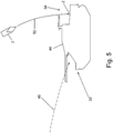
Die Erfindung ermöglicht die Bekämpfung von stark (v.a. in der Frontpartie) gepanzerten Zielen durch das Geschoss, insbesondere eine Hohl- oder P-Ladung (oder Kombination) auf der schwächer gepanzerten Oberseite des Ziels (z. B. Kampfpanzer).The invention makes it possible to combat heavily armored targets (especially in the front) through the projectile, in particular a hollow or P charge (or combination) on the weakly armored upper side of the target (e.g. main battle tank).
Die Erfindung eignet sich sowohl für Drall-stabilisierte als auch für Flügel-stabilisierte Geschosse.The invention is suitable for both spin-stabilized and wing-stabilized projectiles.
In einer bevorzugten Ausführungsform ist das Bremselement ein passiv wirkendes Bremselement. Das Bremselement weist beim Flug des Geschosses eine - zwischen Ruhezustand und Bremszustand - veränderbare aerodynamische Wirkung (keine oder merkliche bzw. in der Stärke veränderliche Bremskraft bzw. Bremswirkung) auf. Das Bremselement ist insbesondere aus dem Geschoss ausfahrbar und/oder beweglich und/oder dessen aerodynamisch wirksamer Querschnitt ist veränderbar. Derartige Bremselemente sind konstruktiv besonders einfach und unaufwändig zu realisieren.In a preferred embodiment, the braking element is a passive braking element. When the projectile is in flight, the braking element has an aerodynamic effect which can be changed between the idle state and the braking state (no or noticeable braking force or braking effect which varies in strength). The braking element can be extended and / or moved in particular from the projectile and / or its aerodynamically effective cross section can be changed. Such brake elements are structurally particularly simple and inexpensive to implement.
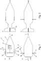
In einer bevorzugten Variante dieser Ausführungsform ist das Bremselement relativ zum Grundkörper beweglich. Insbesondere ist das Bremselement ausfahrbar und/oder ausklappbar, insbesondere ist es eine Bremsklappe oder ein Bremsflügel. Dies bezieht sich insbesondere auf eine Umrissform des Geschosses im Ruhezustand. Gemäß der Erfindung öffnen (Aktivierung des Bremszustandes) insbesondere zusätzliche Bremsklappen als Bremselemente nach einer programmierten Zeit (Bremskriterium) und erhöhen den Luftwiderstand des Geschosses erheblich.In a preferred variant of this embodiment, the braking element is movable relative to the base body. In particular, the brake element can be extended and / or folded out, in particular it is a brake flap or a brake wing. This relates in particular to an outline shape of the projectile in the idle state. According to the invention, (activation of the braking state), in particular, additional brake flaps open as braking elements after a programmed time (braking criterion) and increase the air resistance of the projectile considerably.
In einer bevorzugten Ausführungsform ist das Bremselement ein (zumindest im Bremszustand) aktiv wirkendes Bremselement. Das Bremselement ist also in irgendeiner Weise energiebetrieben bzw. nutzt Energie zur Abbremsung des Geschosses. Denkbar sind durch in der Steuereinrichtung gespeicherte Energie angetriebene, der Abbremsung dienende Antriebe usw. Hierdurch kann die Bremskraft bzw. Bremswirkung gegenüber passiv wirkenden Bremselementen verstärkt werden.In a preferred embodiment, the braking element is an active braking element (at least in the braking state). The braking element is therefore in some way energy-operated or uses energy to brake the projectile. It is conceivable to drive energy, stored in the control device, for braking purposes, etc. In this way, the braking force or braking effect can be increased compared to passively acting braking elements.
In einer bevorzugten Variante dieser Ausführungsform enthält das Bremselement eine aktivierbare Rückstoßeinrichtung. Diese setzt insbesondere chemisch gespeicherte Energie frei. Bei bzw. nach der Aktivierung dient die Rückstoßeinrichtung zur Erzeugung einer Rückstoßkraft entgegen der Flugrichtung des Geschosses. Zumindest weist die Rückstoßkraft eine Komponente entgegen der Flugrichtung auf. Eine entsprechende Rückstoßeinrichtung kann besonders einfach und wirkungsvoll zur Abbremsung eingesetzt werden.In a preferred variant of this embodiment, the braking element contains an activatable recoil device. This releases chemically stored energy in particular. During or after activation, the recoil device serves to generate a recoil force against the direction of flight of the projectile. At least the recoil force has a component against the direction of flight. A corresponding recoil device can be used particularly simply and effectively for braking.
In einer bevorzugten Variante dieser Ausführungsform enthält die Rückstoßeinrichtung mindestens einen Auslasskanal. Der Auslasskanal dient zum Auslass eines Rückstoßmittels. Der Auslasskanal erstreckt sich entlang einer Auslassrichtung, wobei die Auslassrichtung zumindest eine Richtungskomponente in Flugrichtung aufweist. Rückstoßmittel bzw. Medium, welches aus dem Auslasskanal und damit auch entlang der Auslassrichtung ausströmt, hat daher ebenfalls eine bremsende Richtungskomponente entgegen der Flugrichtung. Die Auslassrichtung ist insbesondere die Mittellängsachse des Auslasskanals und insbesondere eine Gerade. Eine derartige Rückstoßeinrichtung ist besonders einfach umzusetzen und wirkungsvoll. Rückstoßmittel sind beispielsweise Druckluft, Triebwerks-, Brand- oder Explosionsgase, Partikel, das Ausstoßprodukt eines (Raketen-)Treibsatzes usw.In a preferred variant of this embodiment, the recoil device contains at least one outlet channel. The outlet channel serves to discharge a recoil. The outlet channel extends along an outlet direction, the outlet direction having at least one direction component in the flight direction. Recoil means or medium, which flows out of the outlet channel and thus also along the outlet direction, therefore likewise has a braking direction component against the flight direction. The outlet direction is in particular the central longitudinal axis of the outlet channel and in particular a straight line. Such a recoil device is particularly easy to implement and effective. Recoil means are, for example, compressed air, engine, fire or explosion gases, particles, the product of a (rocket) propellant, etc.
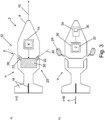
In einer bevorzugten Ausführung Variante dieser Ausführungsform enthält die Rückstoßeinrichtung einen aktivierbaren (insbesondere Raketen-) Treibsatz. Der Treibsatz dient zur Erzeugung und/oder Freisetzung des Rückstoßmittels in Form des Ausstoßprodukts des Treibsatzes. Durch einen entsprechenden Treibsatz kann besonders einfach und wirkungsvoll eine Abbremsung des Geschosses erfolgen.In a preferred embodiment variant of this embodiment, the recoil device contains an activatable (in particular rocket) propellant. The propellant serves to generate and / or release the recoil in the form of the propellant's product. The projectile can be braked particularly easily and effectively by means of an appropriate propellant charge.
Insbesondere wird der Treibsatz nach bzw. zu einer programmierten Zeit nach dem Abschuss des Geschosses gezündet. Der Treibsatz generiert dann durch die nach vorne (in Flugrichtung) gerichteten Auslässe (äußere Enden der Auslasskanäle) einen Rückwärtsschub, welcher zur Abbremsung des Geschosses führt. In particular, the propellant charge is ignited after or at a programmed time after the projectile has been fired. The propellant charge then generates a backward thrust through the outlets (outer ends of the outlet ducts) facing forwards (in the direction of flight), which leads to the projectile being braked.
In einer bevorzugten Ausführungsform ist das Bremskriterium ein Ablauf einer vorgebbaren Flugdauer nach dem Abschuss des Geschosses. Mit anderen Worten wird im Geschoss eine Zeitdauer zwischen Abschuss und Aktivierung des Bremszustandes eingestellt. Bei bekannter Fluggeschwindigkeit des Geschosses kann somit die Abbremsung und damit die gezielte Umlenkung des Geschosses auf einer gewünschten verkürzten Flugbahn zu einem gewünschten Zielort hin auf einfache Weise erfolgen.In a preferred embodiment, the braking criterion is an expiry of a predefinable flight duration after the projectile has been fired. In other words, a period of time between firing and activation of the braking state is set in the projectile. With the known flight speed of the projectile, the braking and thus the targeted deflection of the projectile can take place in a simple manner on a desired shortened trajectory to a desired destination.
In einer bevorzugten Ausführungsform enthält die Steuereinrichtung ein Lenkmodul zur Steuerung und/oder Regelung der Flugbahn des Geschosses nach dessen Abschuss. Das Lenkmodul kann beispielsweise Luftleitmittel wie bewegliche Lenkflügel, Querbeschleunigungseinrichtungen wie Thruster usw. enthalten, um die verkürzte Flugbahn des Geschosses zumindest in gewissen Grenzen nochmals gezielt zu verändern. Insbesondere kann das Geschoss so auf eine verkürzte Soll-Flugbahn gebracht oder auf dieser gehalten werden. Die Lenkung kann zum Beispiel anhand der Position des Geschosses, der Position eines Ziels, anhand empfangener Steuersignale usw. erfolgen. Das Geschoss kann damit besonders ortsgenau zu einem Zielort geführt werden.In a preferred embodiment, the control device contains a steering module for controlling and / or regulating the trajectory of the projectile after it has been fired. The steering module can contain, for example, air guiding means such as movable steering wings, lateral acceleration devices such as thrusters, etc., in order to specifically change the shortened trajectory of the projectile again, at least within certain limits. In particular, the projectile can be brought to a shortened target trajectory or can be held there. The steering can take place, for example, on the basis of the position of the projectile, the position of a target, on the basis of control signals received, etc. The floor can thus be guided to a destination in a particularly precise location.
Während die Erfindung an sich ausschließlich die Ballistik bzw. Schwerkraft des Geschosses nutzt, um anhand der Abbremsung des Geschosses die Flugbahn zu verkürzen, bedient sich das Lenkmodul aktiver bzw. aerodynamischer Lenkmechanismen wie z. B. verstellbare Lenkflügel, Thruster o. ä. Die Abbremsung bewirkt daher insbesondere die Festlegung der prinzipiellen Flugbahn des Geschosses bzw. der Festlegung im großen Maßstab, das Lenkmodul dient dagegen eher einer Feinkorrektur um die unkorrigierte Flugbahn herum bzw. in deren Nähe.While the invention itself uses only the ballistics or gravity of the projectile to shorten the trajectory based on the braking of the projectile, the steering module uses active or aerodynamic steering mechanisms such as. B. adjustable steering wing, thruster or the like. The braking therefore causes in particular the determination of the basic trajectory of the projectile or the definition on a large scale, the steering module, on the other hand, serves rather a fine correction around the uncorrected trajectory or in the vicinity.
In einer bevorzugten Variante dieser Ausführungsform enthält das Lenkmodul daher ein Zielführungsmodul zur Führung des Geschosses zu einem vorgebbaren Zielort hin. Das Zielführungsmodul orientiert sich zum Beispiel an einer auf ein Zielobjekt am Zielort aufgebrachten Zielmarkierung, an Zielkoordinaten usw. Insbesondere regelt das Lenkmodul das Geschoss auf eine gewünschte verkürzte Flugbahn hin ein. Mit dem Zielführungsmodul kann insbesondere die oben genannte präzise Zielführung des Geschosses realisiert werden.In a preferred variant of this embodiment, the steering module therefore contains a route guidance module for guiding the projectile to a predefinable destination. The route guidance module is oriented, for example, to a target marking applied to a target object at the target location, to target coordinates, etc. In particular, the steering module regulates the projectile to a desired shortened trajectory. With the route guidance module, the above-mentioned precise route guidance of the storey can be realized in particular.
In einer bevorzugten Ausführungsform enthält die Steuereinrichtung ein Sensormodul. Denkbar ist hierbei jegliche Sensorik zur Gewinnung von Sensordaten, z. B. Lage-, Richtungs-, Geschwindigkeitssensoren usw. Denkbar sind auch Zielsuchsensoren wie z. B. Laser-, Radar-, Kamerasensoren usw. Denkbar sind auch Sensoren in Form von Kommunikationsempfängern oder -sendern zur Kommunikation des Geschosses mit einer Leitstelle oder ähnlichem. Dem Geschoss können somit beliebig komplexe Eigenschaften zugewiesen werden, insbesondere um zum Beispiel eine Zielführung zu verbessern, Eigenbeschuss zu verhindern, Sicherheitsmechanismen zu etablieren usw.In a preferred embodiment, the control device contains a sensor module. Any sensor technology for obtaining sensor data, e.g. B. position, direction, speed sensors, etc. Target search sensors such as. B. laser, radar, camera sensors, etc. sensors in the form of communication receivers or transmitters for communicating the projectile with a control center or the like are also conceivable. Properties of any complexity can thus be assigned to the projectile, in particular, for example, to improve route guidance, prevent self-bombardment, establish security mechanisms, etc.
In einer bevorzugten Variante dieser Ausführungsform enthält daher das Sensormodul ein Lagemodul zur Bestimmung einer aktuellen Lage des Geschosses zumindest während dessen Fluges. Somit ist die zur Zielführung nützliche aktuelle jeweilige Position, Geschwindigkeit, Richtung, Ort usw., also die Lage des Geschosses im Geschoss selbst bekannt und kann dort direkt und schnell weiterverarbeitet werden.In a preferred variant of this embodiment, the sensor module therefore contains a position module for determining a current position of the projectile, at least during its flight. Thus, the current position, speed, direction, location, etc., which is useful for route guidance, is known, i.e. the position of the floor in the floor itself, and can be processed there directly and quickly.
Die Aufgabe der Erfindung wird auch gelöst durch ein Geschoss gemäß Patentanspruch 13. Das Geschoss wurde oben bereits genannt und enthält die erfindungsgemäße Steuereinrichtung und den im Zusammenhang mit dieser genannten Grundkörper. Die Steuereinrichtung ist mit dem Grundkörper zum Geschoss zusammengebaut.The object of the invention is also achieved by a projectile according to claim 13. The projectile has already been mentioned above and contains the control device according to the invention and the base body mentioned in connection with this. The control device is assembled with the base body to form a floor.
Das Geschoss und zumindest ein Teil dessen Ausführungsformen sowie die jeweiligen Vorteile wurden sinngemäß bereits im Zusammenhang mit der erfindungsgemäßen Steuereinrichtung erläutert.The projectile and at least part of its embodiments and the respective advantages have already been explained in connection with the control device according to the invention.
Das Geschoss ist insbesondere ein panzerbrechendes Geschoss bzw. Teil einer panzerbrechenden Munition oder Panzermunition. Das Geschoss ist insbesondere ein 120mm Glattrohr-Geschoss oder ein 155mm-Lenkgeschoss. Das Geschoss enthält insbesondere eine Hohlladung und/oder eine P-Ladung (projektilbildende Ladung).The projectile is in particular an armor-piercing projectile or part of an armor-piercing ammunition or tank ammunition. The projectile is in particular a 120mm smooth-tube projectile or a 155mm steering projectile. The projectile contains in particular a shaped charge and / or a P charge (projectile-forming charge).
Die Aufgabe der Erfindung wird auch gelöst durch eine Munition mit dem Geschoss und der oben genannten Treibladung. Für die Munition ergeben sich die gleichen Vorteile und Ausführungsformen, wie sie sinngemäß bereits oben für das Geschoss genannt wurden.The object of the invention is also achieved by ammunition with the projectile and the above-mentioned propellant charge. The same advantages and embodiments result for the ammunition as have already been mentioned above for the projectile.
Die Aufgabe der Erfindung wird auch gelöst durch ein Verfahren gemäß Patentanspruch 14 zum Betreiben eines erfindungsgemäßen Geschosses. Bei dem Verfahren wird das Geschoss aus einer Waffe abgeschossen. Anschließend wird mindestens eines der Bremselemente während des Fluges in den Bremszustand verbracht.The object of the invention is also achieved by a method according to claim 14 for operating a projectile according to the invention. In the process, the projectile is fired from a weapon. Then at least one of the braking elements is brought into the braking state during the flight.
Das Verfahren und zumindest ein Teil dessen Ausführungsformen sowie die jeweiligen Vorteile wurden sinngemäß bereits im Zusammenhang mit dem erfindungsgemäßen Geschoss bzw. der Steuereinrichtung erläutert. The method and at least some of its embodiments and the respective advantages have already been explained in connection with the projectile according to the invention or the control device.
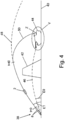
Die Aufgabe der Erfindung wird auch gelöst durch ein Verfahren gemäß Patentanspruch 15 zum Bekämpfen eines Zielobjekts an einem Zielort mit Hilfe des erfindungsgemäßen Verfahrens. Dabei wird das Geschoss aus der Waffe zunächst auf eine reguläre Flugbahn abgeschossen. Dabei wird eine Elevation der Waffe gewählt, die bezüglich einer Elevation für eine auf das Zielobjekt gerichtete Direktflugbahn des Geschosses erhöht ist. Die Direktflugbahn ist diejenige, die ein konventionelles Geschoss oder das erfindungsgemäße Geschoss durchfliegen würde, wenn es vollständig im Ruhezustand verbleiben würde. Hierbei kann es sich um eine gedachte Flugbahn handeln, wenn zum Beispiel tatsächlich eine Deckung oder ein Hindernis in dieser Direktflugbahn vorhanden ist und das Zielobjekt daher konventionell auf der Direktflugbahn gar nicht beschießbar ist. Tatsächlich wird das Geschoss also auf einer zur Direktflugbahn erhöhten regulären Flugbahn verschossen. Entlang der regulären Flugbahn würde insbesondere nicht der Zielort am Zielobjekt getroffen. Die reguläre Flugbahn ist diejenige, die das Geschoss durchfliegen würde, wenn der Ruhezustand beibehalten würde.The object of the invention is also achieved by a method according to claim 15 for combating a target object at a target location with the aid of the method according to the invention. The projectile is first fired from the weapon onto a regular trajectory. In this case, an elevation of the weapon is selected which is increased with respect to an elevation for a direct trajectory of the projectile aimed at the target object. The direct flight path is the one that would fly through a conventional projectile or the projectile according to the invention if it remained completely in the idle state. This can be an imaginary trajectory if, for example, there is actually a cover or an obstacle in this direct trajectory and the target object cannot therefore be bombarded conventionally on the direct trajectory. In fact, the projectile is fired on a regular trajectory elevated to the direct trajectory. In particular, the destination would not be hit at the target object along the regular trajectory. The regular trajectory is the one that would go through the projectile if the hibernation were maintained.
Das Geschoss bzw. mindestens eines der Bremselemente wird dann während des Fluges derart, insbesondere zu einem solchen Zeitpunkt nach dem Abschuss, in den Bremszustand verbracht, dass das gebremste Geschoss durch die Abbremsung vermittels des Bremszustandes aus seiner regulären Flugbahn, die es im Ruhezustand weiterfliegen würde, ballistisch bzw. durch die Schwerkraft nach unten auf einen Zielort am Zielobjekt hin abgelenkt wird. Das Geschoss beschreibt daher insgesamt eine verkürzte Flugbahn, die von der regulären Flugbahn abweicht. Der Zielort am Zielobjekt ist insbesondere ein solcher, welcher durch einen Direktbeschuss mit dem Geschoss auf der Direktflugbahn nicht erreicht werden könnte.The projectile or at least one of the braking elements is then brought into the braking state during the flight, in particular at such a point in time after the launch, that the braking projectile is decelerated by braking from its regular trajectory, which it would continue to fly in the idle state , is deflected ballistically or by gravity downward to a target location at the target object. The projectile therefore describes an overall shortened trajectory that deviates from the regular trajectory. The target location at the target object is in particular one that could not be reached by direct shelling with the projectile in the direct trajectory.
Mit anderen Worten wird das Geschoss zunächst in Richtung „über das Ziel hinausgeschossen“, d. h. auf einer aktuell höheren regulären Flugbahn geführt, die gegenüber der (bei Direktbeschuss auf einer gedachten Bahn zum Ziel führenden) Direktflugbahn erhöht ist. Durch Aktivierung mindestens eines der Bremselemente bei Erreichen des Bremskriteriums, insbesondere zu einem bestimmten Zeitpunkt (das Kriterium bzw. die Berechnung ergibt sich z. B. anhand der Zielkoordinaten des Zielortes und der ballistischen Eigenschaften des Geschosses in fachüblicher Weise) wird das Ziel im Vergleich zum Direktbeschuss mehr von oben getroffen. Ein Direktbeschuss auf der Direktflugbahn würde dagegen das Ziel tiefer, d. h. eher seitlich treffen.In other words, the projectile is first "shot over the target", i.e. H. on a currently higher regular trajectory, which is higher than the direct trajectory (which leads to the target in the case of direct shelling on an imaginary trajectory). By activating at least one of the braking elements when the braking criterion is reached, in particular at a specific point in time (the criterion or the calculation results, for example, from the target coordinates of the target location and the ballistic properties of the projectile in a manner customary in the art), the target becomes compared to Direct bombardment hit more from above. A direct fire on the direct trajectory, on the other hand, would lower the target; H. rather hit sideways.
Idee der Erfindung ist es dabei, dass z. B. ein Kampfpanzer in seiner Frontpartie stark gepanzert, an der Oberseite aber schwächer gepanzert ist. Ein erhöhter Abschusswinkel und eine durch die Abbremsung stark gekrümmte (verkürzte) Flugbahn hilft, das Ziel eher von oben zu treffen. Auch können so Deckungen und Hindernisse überwunden werden, die einen tatsächlichen Direktbeschuss verhindern würden.The idea of the invention is that z. B. a battle tank is heavily armored in its front section, but is weaker armored on the top. An increased firing angle and a trajectory that is heavily curved (shortened) due to braking helps to hit the target from above. Coverages and obstacles that would prevent an actual direct fire can also be overcome in this way.
Weitere Merkmale, Wirkungen und Vorteile der Erfindung ergeben sich aus der nachfolgenden Beschreibung eines bevorzugten Ausführungsbeispiels der Erfindung sowie der beigefügten Figuren. Dabei zeigen, jeweils in einer schematischen Prinzipskizze:
-
1 ein Drall-stabilisiertes Geschoss mit Bremsklappen im a) Ruhezustand und b) Bremszustand, -
2 entsprechend1 ein Flügel-stabilisiertes Geschoss im a) Ruhezustand und b) Bremszustand, -
3 ein Geschoss mit Treibsatz im a) Ruhezustand und b) Bremszustand, -
4 den Beschuss eines Zielobjekts mit einem Geschoss, -
5 das Zielobjekt aus 4 im Detail.
-
1 a spin-stabilized projectile with brake flaps in a) idle state and b) braking state, -
2nd corresponding1 a wing-stabilized projectile in a) idle state and b) braking state, -
3rd one projectile with propellant in a) idle state and b) braking state, -
4th firing a bullet at a target, -
5 the target object4th in detail.
Die Steuereinrichtung
Die Steuereinrichtung
Das Bremskriterium
Das Bremselement
Um vom Ruhezustand
Das Aktivierungsmodul
Im Ruhezustand
Außerdem enthält die Steuereinrichtung
Das Geschoss
BezugszeichenlisteReference symbol list
- 22nd
- Geschossbullet
- 44th
- GrundkörperBasic body
- 66
- SteuereinrichtungControl device
- 88th
- GeschützrohrGun barrel
- 1010th
- FlugrichtungFlight direction
- 1212
- BremselementBraking element
- 1414
- AktivierungsmodulActivation module
- 1616
- SchwenkachseSwivel axis
- 1818th
- Flügelwing
- 2020th
- RückstoßeinrichtungRecoil device
- 2222
- AuslasskanalExhaust duct
- 2424th
- RückstoßmittelRecoil
- 2626
- TreibsatzPropellant charge
- 2828
- AuslassrichtungOutlet direction
- 3030th
- LenkmodulSteering module
- 3232
- ZielführungsmodulRoute guidance module
- 3434
- SensormodulSensor module
- 3636
- LagemodulLocation module
- 3838
- Waffeweapon
- 4040
- Geländeterrain
- 4242
- Deckungcover
- 4444
- ZielobjektTarget object
- 4646
- DirektflugbahnDirect trajectory
- 4848
- Flugbahn (regulär)Trajectory (regular)
- 5050
- Flugbahn (verkürzt)Trajectory (shortened)
- 5252
- FrontpartieFront section
- 5454
- Oberseite Top
- RR
- RuhezustandHibernation
- BB
- BremszustandBraking condition
- KK
- BremskriteriumBraking criterion
- FF
- BremskraftBraking force
- ZZ
- ZielortDestination
- E0,1E0.1
- Elevationelevation
- tt
- Zeitpunkttime
- t0t0
- FlugdauerFlight duration
Claims (15)
Priority Applications (2)
| Application Number | Priority Date | Filing Date | Title |
|---|---|---|---|
| DE102018009843.6A DE102018009843A1 (en) | 2018-12-14 | 2018-12-14 | Decelerated direct fire with bullet |
| EP19211897.4A EP3667226A1 (en) | 2018-12-14 | 2019-11-27 | Projectile steering system with activatable brake unit |
Applications Claiming Priority (1)
| Application Number | Priority Date | Filing Date | Title |
|---|---|---|---|
| DE102018009843.6A DE102018009843A1 (en) | 2018-12-14 | 2018-12-14 | Decelerated direct fire with bullet |
Publications (1)
| Publication Number | Publication Date |
|---|---|
| DE102018009843A1 true DE102018009843A1 (en) | 2020-06-18 |
Family
ID=68731707
Family Applications (1)
| Application Number | Title | Priority Date | Filing Date |
|---|---|---|---|
| DE102018009843.6A Withdrawn DE102018009843A1 (en) | 2018-12-14 | 2018-12-14 | Decelerated direct fire with bullet |
Country Status (2)
| Country | Link |
|---|---|
| EP (1) | EP3667226A1 (en) |
| DE (1) | DE102018009843A1 (en) |
Families Citing this family (2)
| Publication number | Priority date | Publication date | Assignee | Title |
|---|---|---|---|---|
| US11835319B2 (en) * | 2021-06-07 | 2023-12-05 | The Boeing Company | Guided projectile and countermeasure systems and methods for use therewith |
| DE102022000529A1 (en) | 2022-02-11 | 2023-08-17 | Diehl Defence Gmbh & Co. Kg | Guidance of spinning projectiles by cyclic footprint deflection |
Citations (9)
| Publication number | Priority date | Publication date | Assignee | Title |
|---|---|---|---|---|
| US3442083A (en) * | 1967-07-21 | 1969-05-06 | Avco Corp | Adjustable variable thrust propulsion device |
| DE69121427T2 (en) * | 1990-01-26 | 1997-01-02 | Thomson Brandt Armements | Projectile and its method of use |
| DE69909719T2 (en) * | 1998-11-30 | 2004-04-08 | Giat Industries | Braking device for the trajectory velocity of a projectile |
| US7350744B1 (en) * | 2006-02-22 | 2008-04-01 | Nira Schwartz | System for changing warhead's trajectory to avoid interception |
| US20080223246A1 (en) * | 2007-03-13 | 2008-09-18 | Dindl Frank J | Burping projectile |
| WO2009022995A2 (en) * | 2007-08-13 | 2009-02-19 | Stefan Kemenyik | Progressive fire extinguishing and technology for powder medium application |
| US20090283627A1 (en) * | 2008-05-16 | 2009-11-19 | Raytheon Company | Methods and apparatus for air brake retention and deployment |
| US20100032516A1 (en) * | 2008-06-13 | 2010-02-11 | Raytheon Company | Solid-fuel pellet thrust and control actuation system to maneuver a flight vehicle |
| WO2013119163A1 (en) * | 2012-02-06 | 2013-08-15 | Bae Systems Bofors Ab | Brake panel for a detonator or a projectile |
Family Cites Families (8)
| Publication number | Priority date | Publication date | Assignee | Title |
|---|---|---|---|---|
| GB821935A (en) * | 1954-09-15 | 1959-10-14 | Metallbau Semler G M B H | Improvements in or relating to the propulsion and/or control of flying bodies |
| US4519315A (en) * | 1982-12-20 | 1985-05-28 | The United States Of America As Represented By The Secretary Of The Army | Fire and forget missiles system |
| DE3643294A1 (en) * | 1986-12-18 | 1988-06-23 | Rheinmetall Gmbh | BULLET |
| DE3904684A1 (en) * | 1989-02-16 | 1990-09-20 | Asea Brown Boveri | METHOD FOR CORRECTING THE FLIGHT TRUCK EXPLOSIVE SHELL LAUNCHED OR SELF-DRIVEN FROM A PISTON WEAPON AND BULLET TO WHICH THE METHOD IS APPLIED |
| DE19861399B4 (en) * | 1998-05-29 | 2009-04-30 | Rheinmetall Waffe Munition Gmbh | GPS-supported projectile |
| GB9813558D0 (en) * | 1998-06-24 | 2002-03-06 | Royal Ordnance Plc | Device for exerting drag |
| DE50012396D1 (en) * | 1999-09-27 | 2006-05-11 | Dynamit Nobel Defence Gmbh | Armor piercing ammo |
| DE10143312C1 (en) * | 2001-09-04 | 2003-06-18 | Diehl Munitionssysteme Gmbh | Braking device for a path-correctable spin-stabilized artillery projectile |
-
2018
- 2018-12-14 DE DE102018009843.6A patent/DE102018009843A1/en not_active Withdrawn
-
2019
- 2019-11-27 EP EP19211897.4A patent/EP3667226A1/en not_active Withdrawn
Patent Citations (9)
| Publication number | Priority date | Publication date | Assignee | Title |
|---|---|---|---|---|
| US3442083A (en) * | 1967-07-21 | 1969-05-06 | Avco Corp | Adjustable variable thrust propulsion device |
| DE69121427T2 (en) * | 1990-01-26 | 1997-01-02 | Thomson Brandt Armements | Projectile and its method of use |
| DE69909719T2 (en) * | 1998-11-30 | 2004-04-08 | Giat Industries | Braking device for the trajectory velocity of a projectile |
| US7350744B1 (en) * | 2006-02-22 | 2008-04-01 | Nira Schwartz | System for changing warhead's trajectory to avoid interception |
| US20080223246A1 (en) * | 2007-03-13 | 2008-09-18 | Dindl Frank J | Burping projectile |
| WO2009022995A2 (en) * | 2007-08-13 | 2009-02-19 | Stefan Kemenyik | Progressive fire extinguishing and technology for powder medium application |
| US20090283627A1 (en) * | 2008-05-16 | 2009-11-19 | Raytheon Company | Methods and apparatus for air brake retention and deployment |
| US20100032516A1 (en) * | 2008-06-13 | 2010-02-11 | Raytheon Company | Solid-fuel pellet thrust and control actuation system to maneuver a flight vehicle |
| WO2013119163A1 (en) * | 2012-02-06 | 2013-08-15 | Bae Systems Bofors Ab | Brake panel for a detonator or a projectile |
Non-Patent Citations (3)
| Title |
|---|
| RPG (Waffe). In: Wikimedia Foundation Inc. (Hrsg.): Wikipedia - Die freie Enzyklopädie, 2018, URL: https://de.wikipedia.org/w/index.php?title=RPG_(Waffe)&oldid=180323390 [abgerufen am 13.02-2019]. - Version vom 25. August 2018 um 15:00 Uhr * |
| SMArt 155. In: Wikimedia Foundation Inc. (Hrsg.): Wikipedia - Die freie Enzyklopädie, 2018, URL: https://de.wikipedia.org/w/index.php?title=SMArt_155&oldid=181966690 [abgerufen am 13.02-2019]. - Version vom 20. Oktober 2018 um 14:12 Uhr * |
| Spike (Panzerabwehrlenkwaffe). In: Wikimedia Foundation Inc. (Hrsg.): Wikipedia - Die freie Enzyklopädie, 2018, URL: https://de.wikipedia.org/w/index.php?title=Spike_(Panzerabwehrlenkwaffe)&oldid=182626192 [abgerufen am 13.02-2019]. - Version vom 10. November 2018 um 14:21 Uhr * |
Also Published As
| Publication number | Publication date |
|---|---|
| EP3667226A1 (en) | 2020-06-17 |
Similar Documents
| Publication | Publication Date | Title |
|---|---|---|
| DE19740888C2 (en) | Method for autonomously steering a spin-stabilized artillery projectile and autonomously guided artillery projectile for carrying out the method | |
| DE4325218C2 (en) | Artillery missile and method for increasing the performance of an artillery missile | |
| DE102012005682B4 (en) | Method for directing an active element by a shooter | |
| DE102005007910A1 (en) | Firearm for long flight duration projectiles has fire guidance system with target data acquisition and adjusters for sight tube on weapon | |
| EP2482026B1 (en) | Method for defending against an attack by a missile | |
| EP2413086A2 (en) | Method for controlling a guided missile powered by an engine | |
| EP3667226A1 (en) | Projectile steering system with activatable brake unit | |
| EP2213975A2 (en) | Cargo projectile | |
| DE102020007514A1 (en) | Weapon system for a combat vehicle, combat vehicle with the weapon system and method for defeating reactive armor | |
| DE3142742C2 (en) | ||
| EP1983294B1 (en) | Method and device for combating a launching position of an attack munition | |
| DE102010053896A1 (en) | Target engagement system | |
| DE3013405A1 (en) | METHOD FOR AVOIDING MESSAGE FROM LAUNCHERS FOR BALLISTIC missiles | |
| DE60302281T2 (en) | Weapon containing a rocket mounted on a stealth plane and weapon system containing a stealth plane and such a weapon | |
| DE69925368T2 (en) | Method and device for correcting the trajectory of a rotation-stabilized projectile | |
| EP3943874A1 (en) | Effector for combating a target | |
| DE3221039C2 (en) | Missile that can be fired from a launch tube | |
| DE965185C (en) | Aerodynamically stabilized, uncontrollable flying body | |
| EP3376154B1 (en) | Method for protecting a cruise missile | |
| DE3529897C2 (en) | ||
| EP0049778B1 (en) | Method for the distribution of ammunition | |
| DE102012003990A1 (en) | Ammunition e.g. artillery ammunition has bullet tail with control unit that produces control signal for controlling actuator based on determined spatial position of ammunition and trajectory of ammunition | |
| DE3919631A1 (en) | Supersonic anti-aircraft or armour-piercing projectile | |
| EP1612504B1 (en) | Warhead for ordnance ammunition | |
| DE2815206C2 (en) | Procedure, guided missile and weapon system for combating ground targets |
Legal Events
| Date | Code | Title | Description |
|---|---|---|---|
| R012 | Request for examination validly filed | ||
| R016 | Response to examination communication | ||
| R120 | Application withdrawn or ip right abandoned |