DE102015114993B4 - Mobile wood bundle device - Google Patents
Mobile wood bundle device Download PDFInfo
- Publication number
- DE102015114993B4 DE102015114993B4 DE102015114993.1A DE102015114993A DE102015114993B4 DE 102015114993 B4 DE102015114993 B4 DE 102015114993B4 DE 102015114993 A DE102015114993 A DE 102015114993A DE 102015114993 B4 DE102015114993 B4 DE 102015114993B4
- Authority
- DE
- Germany
- Prior art keywords
- wood
- bundle
- wall
- bundling
- front wall
- Prior art date
- Legal status (The legal status is an assumption and is not a legal conclusion. Google has not performed a legal analysis and makes no representation as to the accuracy of the status listed.)
- Expired - Fee Related
Links
- 239000002023 wood Substances 0.000 title claims abstract description 74
- 230000008878 coupling Effects 0.000 claims abstract description 18
- 238000010168 coupling process Methods 0.000 claims abstract description 18
- 238000005859 coupling reaction Methods 0.000 claims abstract description 18
- 230000002441 reversible effect Effects 0.000 claims abstract 2
- 239000002689 soil Substances 0.000 claims description 3
- 238000004804 winding Methods 0.000 description 4
- ATJFFYVFTNAWJD-UHFFFAOYSA-N Tin Chemical compound [Sn] ATJFFYVFTNAWJD-UHFFFAOYSA-N 0.000 description 2
- 238000003780 insertion Methods 0.000 description 2
- 230000037431 insertion Effects 0.000 description 2
- 239000002184 metal Substances 0.000 description 2
- 238000003825 pressing Methods 0.000 description 2
- 239000013590 bulk material Substances 0.000 description 1
- 239000000969 carrier Substances 0.000 description 1
- 238000010276 construction Methods 0.000 description 1
- 238000001035 drying Methods 0.000 description 1
- 230000000694 effects Effects 0.000 description 1
- 238000000034 method Methods 0.000 description 1
- 230000000276 sedentary effect Effects 0.000 description 1
- 230000006641 stabilisation Effects 0.000 description 1
- 238000011105 stabilization Methods 0.000 description 1
Images

Classifications
-
- A—HUMAN NECESSITIES
- A01—AGRICULTURE; FORESTRY; ANIMAL HUSBANDRY; HUNTING; TRAPPING; FISHING
- A01G—HORTICULTURE; CULTIVATION OF VEGETABLES, FLOWERS, RICE, FRUIT, VINES, HOPS OR SEAWEED; FORESTRY; WATERING
- A01G23/00—Forestry
-
- B—PERFORMING OPERATIONS; TRANSPORTING
- B65—CONVEYING; PACKING; STORING; HANDLING THIN OR FILAMENTARY MATERIAL
- B65B—MACHINES, APPARATUS OR DEVICES FOR, OR METHODS OF, PACKAGING ARTICLES OR MATERIALS; UNPACKING
- B65B13/00—Bundling articles
- B65B13/18—Details of, or auxiliary devices used in, bundling machines or bundling tools
- B65B13/20—Means for compressing or compacting bundles prior to bundling
-
- B—PERFORMING OPERATIONS; TRANSPORTING
- B65—CONVEYING; PACKING; STORING; HANDLING THIN OR FILAMENTARY MATERIAL
- B65B—MACHINES, APPARATUS OR DEVICES FOR, OR METHODS OF, PACKAGING ARTICLES OR MATERIALS; UNPACKING
- B65B27/00—Bundling particular articles presenting special problems using string, wire, or narrow tape or band; Baling fibrous material, e.g. peat, not otherwise provided for
- B65B27/10—Bundling rods, sticks, or like elongated objects
Landscapes
- Engineering & Computer Science (AREA)
- Mechanical Engineering (AREA)
- Life Sciences & Earth Sciences (AREA)
- Biodiversity & Conservation Biology (AREA)
- Ecology (AREA)
- Forests & Forestry (AREA)
- Environmental Sciences (AREA)
- Pallets (AREA)
- Basic Packing Technique (AREA)
- Floor Finish (AREA)
- Body Structure For Vehicles (AREA)
Abstract
Die Erfindung betrifft ein mobiles Holzbündelgerät mit einem Boden (10), einer sich von einem rückseitigen Rand des Bodens (10) aufwärts erstreckenden Rückwand (18), einer Ankoppelungseinrichtung an Boden (10) und/oder Rückwand (18), mit der das Holzbündelgerät an ein Fahrzeug reversibel ankoppelbar ist, wobei eine mit einem vorderseitigen Rand des Bodens (10) reversibel koppelbare Frontwand (30), eine Quertraverse (32), die die Rückwand (18) und die Frontwand (30) miteinander verbindet, wobei zwischen Boden (10) und Quertraverse (32) einerseits sowie zwischen Rückwand (18) und Frontwand (30) andererseits ein seitlich zugänglicher, quaderförmiger Bündelraum definiert ist, und einer Antriebseinrichtung, die die Quertraverse (32) und die Frontwand (30) in eine zurückgezogene Bündelentladeposition, in der die Frontwand (30) vom Boden (10) entkoppelt ist, bewegen kann.The invention relates to a mobile wood bundling apparatus having a bottom (10), a rear wall (18) extending upward from a rear edge of the floor (10), a coupling device to the floor (10) and / or rear wall (18), to which the wood bundling device a reversible coupled to a front edge of the bottom (10) front wall (30), a cross-beam (32) connecting the rear wall (18) and the front wall (30) to each other, wherein between ground ( 10) and transverse member (32) on the one hand and between the rear wall (18) and front wall (30) on the other hand, a laterally accessible, cuboid bundling space is defined, and a drive means, the cross-beam (32) and the front wall (30) in a retracted Bündelentladeposition, in which the front wall (30) is decoupled from the ground (10) can move.
Description
Die Erfindung betrifft ein mobiles Holzbündelgerät. The invention relates to a mobile wood bundling device.
Brennholz wird zunehmend nicht als Schüttgut transportiert, sondern in gebündelter Form. So werden beispielsweise Holzpaletten nach Euronorm mit seitlichen Holzwänden versehen, in welche dann die einzelnen Holzabschnitte, die üblicherweise eine Schnittlänge von entweder 330 oder 500 mm haben, eingebündelt werden. Diese Paletten werden dann zu den Händlern oder zum Verbraucher transportiert. Firewood is increasingly not transported as bulk material, but in bundled form. For example, wooden pallets are provided according to Euronorm with side wooden walls, in which then the individual wood sections, which usually have a cutting length of either 330 or 500 mm, are bundled. These pallets are then transported to the dealers or to the consumer.
Darüber hinaus gibt es Holzbündelgeräte, die runde Holzbündel mit einer gewissen Größe, meist 1 Rm, erzeugen. Beim Lagern verformen sich die Bündel aber oft, was die Weiterverarbeitung oder auch den Weitertransport erschweren kann. In addition, there are wood bundles, the round wood bundles with a certain size, usually 1 Rm produce. During storage, however, the bundles often deform, which can make further processing or further transport more difficult.
Aufgabe der Erfindung ist es, ein mobiles Holzbündelgerät zu schaffen, das ein schnelles Bündeln, Transportieren und gegebenenfalls auch Weiterverarbeiten der Holzzuschnitte ermöglicht. The object of the invention is to provide a mobile wood bundle device that allows fast bundling, transporting and possibly also further processing of the wood blanks.
Die Aufgabe wird durch ein mobiles Holzbündelgerät gelöst, mit einem Boden, einer sich von einem rückseitigen Rand des Bodens aufwärts erstreckenden Rückwand, einer Ankoppelungseinrichtung an Boden und/oder Rückwand, mit der das Holzbündelgerät an ein Fahrzeug reversibel ankoppelbar ist, gekennzeichnet durch eine mit einem vorderseitigen Rand des Bodens reversibel koppelbare (d.h. an- und auch wieder abkoppelbare) Frontwand, eine Quertraverse, die die Rückwand und die Frontwand miteinander verbindet, wobei zwischen Boden und Quertraverse einerseits sowie zwischen Rückwand und Frontwand andererseits ein seitlich zugänglicher, quaderförmiger Bündelraum definiert ist, und eine Antriebseinrichtung, die die Quertraverse und die Frontwand in eine Bündelentladeposition bewegen kann, in der die Frontwand vom Boden entkoppelt und frontseitig vom Bündel wegbewegt ist, so dass der Bündelraum frontseitig offen ist. The object is achieved by a mobile wood bundle device, with a bottom, a back wall extending from a rear edge of the floor, a coupling device to the floor and / or rear wall, with which the wood bundle device is reversibly coupled to a vehicle, characterized by a with a front side edge of the floor reversibly coupled (ie on and also decoupled) front wall, a cross-beam, which connects the rear wall and the front wall, between bottom and cross member on the one hand and between the rear wall and front wall on the other hand, a laterally accessible, cuboid bundle space is defined, and a drive means which can move the cross-beam and the front wall into a bundle unloading position in which the front wall is decoupled from the ground and moved away from the bundle at the front so that the bundling space is open at the front.
Das erfindungsgemäße Bündelgerät ist an einen Traktor, Radlader, Unimog oder dergleichen sehr einfach an- und von ihm abkoppelbar (d.h. reversibel ankoppelbar), und es hat einen quaderförmigen Bündelraum, der durch einen Boden, eine Quertraverse, eine Frontwand und eine Rückwand definiert ist. Die Frontwand kann aus einer Position, in der sie mit dem Boden gekoppelt ist und den Bündelraum definiert, in eine Bündelentladeposition gebracht werden, in der der Bündelraum vorderseitig offen ist, so dass das zuvor erzeugte Bündel frontseitig vom Gerät entfernt werden kann, denn die Frontwand steht dem Bündel beim Entladen nicht mehr im Wege. The bundling apparatus according to the invention is very easy to connect to (and reversibly connect to) a tractor, wheel loader, Unimog or the like and has a parallelepiped-shaped bundle space defined by a bottom, a cross-beam, a front wall and a rear wall. The front wall can be brought from a position in which it is coupled to the ground and defines the bundling space in a bundle unloading position in which the bundling space is open on the front, so that the previously generated bundle can be removed from the front of the device, because the front wall is no longer in the way of the bundle when unloading.
Die Antriebseinrichtung kann so ausgeführt sein, dass Sie die Quertraverse und die Frontwand aus der Bündelentladeposition zurück zum vorderseitigen Rand bewegen kann, um den Bündelraum wieder nach vorne und nach oben zu begrenzen. Somit wirkt die Antriebseinrichtung in zwei Richtungen, und zwar von der Bündelentladeposition in die Bündelposition, in der die Frontwand mit dem Boden mechanisch gekoppelt ist, und in die Gegenrichtung. The drive means may be configured so that you can move the cross-beam and the front wall from the bundle unloading position back to the front edge to again limit the bundling space forward and upward. Thus, the drive means acts in two directions, from the bundle unloading position to the bundling position, in which the front wall is mechanically coupled to the ground, and in the opposite direction.
Die Antriebseinrichtung ist bevorzugt eine Schwenkeinrichtung, die an der Quertraverse angreift. Ein Beispiel für die Ausführung einer Schwenkeinrichtung ist ein Hydraulikzylinder, der einen fahrzeugseitigen Hydraulikanschluss aufweisen kann. The drive device is preferably a pivoting device which acts on the crossbeam. An example of the execution of a pivoting device is a hydraulic cylinder, which may have a hydraulic connection on the vehicle side.
Die Quertraverse ist im Bereich des oberen Endes der Rückwand insbesondere beweglich angebracht, um in die Bündelentladeposition bewegt zu werden. The crossbeam is particularly movably mounted in the region of the upper end of the rear wall in order to be moved into the bundle unloading position.
Ferner ist angedacht, die Quertraverse klappbar auszubilden. Hierfür ist die Quertraverse beispielsweise in zwei oder mehr zueinander bewegliche, und zwar über eine Schwenkachse miteinander gekoppelte Abschnitte aufgeteilt. In einer Weiterverarbeitungsposition sind diese schwenkbaren Abschnitte aufeinander zu geklappt, so dass die mit dem frontwandseitigen Ende der Quertraverse gekoppelte Frontwand platzsparend und nahe an die Rückwand gebracht werden kann. Furthermore, it is envisaged to form the crossbeam hinged. For this purpose, the cross-beam, for example, in two or more mutually movable, and in fact divided over a pivot axis coupled sections. In a further processing position, these pivotable sections are folded toward one another, so that the front wall, which is coupled to the front wall-side end of the cross-beam, can be space-savingly brought close to the rear wall.
Die Frontwand kann in der Weiterverarbeitungsposition sogar hinter den den Kontaktraum begrenzenden Kontaktflächen der Rückwand angeordnet sein, an welchen die Holzabschnitte anliegen. In the further processing position, the front wall may even be arranged behind the contact surfaces of the rear wall delimiting the contact space, against which the wood sections abut.
Im Holzbündelgerät selbst kann dann auch das Holzbündel durch Gurte, die das Holzbündel umschlingen, gespannt werden. Hierzu weist das erfindungsgemäße Holzbündelgerät eine Gurtspannvorrichtung auf, über die der das Bündel umschlingende Gurt gespannt werden kann. Eine Variante dieser Gurtspannvorrichtung sieht vor, dass im Bereich der Rückwand eine Wickelwelle gelagert ist, die ein Spannen des Gurtes erlaubt. Diese Wickelwelle kann zusätzlich die Stabilität der Rückwandkonstruktion erhöhen. In the wood bundle device itself, the bundle of wood can then be tensioned by straps that wrap around the wood bundle. For this purpose, the wood bundling device according to the invention has a belt tensioning device, via which the belt wrapping the bundle can be tensioned. A variant of this belt tensioning device provides that in the region of the rear wall a winding shaft is mounted, which allows a tensioning of the belt. This winding shaft can additionally increase the stability of the rear wall construction.
Die Erfindung betrifft darüber hinaus auch ein Holzbündelgerät, welches ein Weiterverarbeiten des auf ihm gebündelten Holzes auf dem Gerät selbst ermöglicht. Dies wird dadurch ermöglicht, dass zumindest eine sich vertikal erstreckende Führung für eine Motorsäge am Holzbündelgerät vorhanden ist. Damit werden lange, insbesondere 1 m lange Holzscheite weiter abgelängt. Nach dem Bündeln, zum Beispiel aber auch nach dem Spannen des Bündels mit einem oder mehreren Gurten, kann über die Führung das Bündel in Längsrichtung geteilt werden, indem eine Motorsäge in der bündelgerätseitigen Führung gehalten oder geführt ist und durch das Holzbündel schneidet. The invention also relates to a wood bundle device, which allows further processing of the wood bundled on it on the device itself. This is made possible by the fact that at least one vertically extending guide for a power saw is present on the wood bundling device. This long, especially 1 m long logs are cut to length. After bundling, for example, but also after tensioning the bundle with one or more straps, the bundle can be divided longitudinally by the guide by: a chainsaw is held or guided in the bundle device side guide and cuts through the bundle of wood.
Vorzugsweise sind dabei mehrere Führungen vorgesehen, um unterschiedliche Scheitlängen realisieren zu können. Beispielsweise ist eine mittige Führung vorhanden, die ein Ablängen auf 500 mm lange Scheite ermöglicht, und zusätzlich zwei weitere Führungen, die ein Ablängen auf 330 mm ermöglichen, wenn die ursprünglichen Holzscheitlängen 1 m betrugen. Preferably, several guides are provided in order to realize different log lengths. For example, there is a central guide that allows for cutting to 500 mm long logs, and additionally two further guides that allow cutting to 330 mm when the original log lengths were 1 m.
Die mindestens eine Führung ist vorzugsweise im Bereich der Rückwand vorgesehen. Die zumindest eine Führung liegt in einer Weiterverarbeitungsposition zum Holzbündel hin frei, so dass in dieser Position die Motorsäge in die Führung eingreifen kann. The at least one guide is preferably provided in the region of the rear wall. The at least one guide is free in a further processing position to the wood bundle, so that in this position the chainsaw can engage in the guide.
Das erfindungsgemäße Holzbündelgerät ist auch besonders einfach zu hantieren und besonders universell als mobiles Holzbündelgerät einsetzbar. Hierzu ist gemäß einer Ausführungsform der Erfindung vorgesehen, dass der Boden frei auskragende Gabeln aufweist, die in Palettenböden, insbesondere in Euro-Paletten, einfahrbar sind. Somit wird das Holzbündel gleich auf einer Palette aufgeschichtet, die im Holzbündelgerät fixiert ist, und zwar über die Gabeln. Der Palettenboden bildet damit die Auflagefläche für das Bündel, das auf ihm gebildet wird. The wood bundling device according to the invention is also particularly easy to handle and particularly universally usable as a mobile wood bundling device. For this purpose, it is provided according to an embodiment of the invention that the bottom has freely projecting forks, which are retractable in pallet floors, especially in Euro pallets. Thus, the bundle of wood is immediately piled on a pallet, which is fixed in the wood bundle device, via the forks. The pallet base thus forms the bearing surface for the bundle formed on it.
Die Gabeln am Holzbündelgerät können vorzugsweise aufeinander zu- und voneinander wegbewegt werden, um flexibel für unterschiedliche Palettenböden eingesetzt zu werden. The forks on the wood bundling device can preferably be moved towards and away from each other to be used flexibly for different pallet floors.
Als einfache Möglichkeit, eine Ankoppelungseinrichtung zu schaffen, sind die Gabeln hohl ausgeführt. Die Gabeln sind ferner von der Rückwand aus offen, so dass fahrzeugseitige Gabeln an einem Traktor oder einem anderen Fahrzeug einfach in die hohlen Gabeln am Holzbündelgerät eingefahren werden können, um das Holzbündelgerät anzuheben. As an easy way to create a coupling device, the forks are made hollow. The forks are also open from the rear wall so that on-board forks on a tractor or other vehicle can be easily retracted into the hollow forks on the wood bundling apparatus to lift the wood bundling apparatus.
Im Bereich der Rückwand können alternativ oder zusätzlich zu diesen hohlen Gabeln auch noch andere Ankoppelungseinrichtungen vorgesehen sein. Insbesondere sind im Bereich der Rückwand Koppelstellen für einen fahrzeugseitigen Dreipunkt-Kraftheber ausgebildet. Ein solcher Dreipunkt-Kraftheber wird auch als Dreipunkthydraulik bezeichnet und dient dazu, als Universalschnittstelle Anbaugeräte oder Arbeitsgeräte an den Traktor hydraulisch anzukoppeln oder anzuheben. Solche Dreipunkt-Kraftheber sind sowohl an der Rückseite eines Traktors als auch an der Frontseite (Heckhubwerk beziehungsweise Fronthubwerk) realisiert. Die Abwärtsbewegung erfolgt entweder hydraulisch oder bei einfachen Systemen durch das eigene Gewicht der Elemente, insbesondere des Unterlenkers beziehungsweise der Anbaugeräte. Die Koppelstellen für den Dreipunkt-Kraftheber können insbesondere quer verlaufende, frei zugängliche Bolzen oder Hohlbolzen oder Aufnahmen hierfür sein. In the area of the rear wall, alternatively or in addition to these hollow forks, other coupling devices may also be provided. In particular, coupling points for a vehicle-side three-point linkage are formed in the region of the rear wall. Such a three-point power lift is also referred to as three-point hydraulic and serves as a universal interface attachments or attachments hydraulically coupled to the tractor or raise. Such three-point power lift are realized both on the back of a tractor and on the front (Heckhubwerk or front hitch). The downward movement is either hydraulically or in simple systems by the weight of the elements, in particular the lower link or the implements. The coupling points for the three-point linkage can in particular be transverse, freely accessible bolts or hollow pins or recordings for this purpose.
Das erfindungsgemäße Holzbündelgerät ist insbesondere so weit wie möglich aus Hohlprofilen zusammengeschweißt, um eine hohe Festigkeit und trotzdem ein geringes Eigengewicht realisieren zu können. The wood bundling device according to the invention is in particular as far as possible welded together from hollow profiles in order to realize a high strength and still a low weight.
Die Rückwand weist beispielsweise außenseitige, das heißt links und rechts angeordnete Hohlträgerprofile auf, von denen Anschlagwände in Richtung zur Vorderseite abstehen. Diese Anschlagwände können zum Beispiel abgewinkelte Bleche sein. Die Kontaktflächen der Anschlagwände werden vom Holzbündel kontaktiert und begrenzen damit den Bündelraum. The rear wall has, for example, on the outside, that is to say left and right, hollow carrier profiles, from which stop walls protrude in the direction of the front side. These stop walls can be, for example, angled sheets. The contact surfaces of the stop walls are contacted by the bundle of wood and thus limit the bundling space.
Zwischen den Hohlträgerprofilen und den Anschlagwänden wird ein Aufnahmeraum gebildet, der optional die Frontwand in der Weiterverarbeitungsposition aufnehmen kann. Somit steht die Frontwand nicht etwa nach oben weit vor, sondern die Quertraverse wird zusammen mit der Frontwand nach oben geschwenkt und anschließend, aufgrund der Faltbarkeit der Quertraverse, nach unten in den Aufnahmeraum sicher eingeführt. Auch in der Weiterverarbeitungsposition hat damit das erfindungsgemäße Holzbündelgerät eine kompakte Form. Between the hollow beam profiles and the stop walls, a receiving space is formed, which can optionally accommodate the front wall in the finishing position. Thus, the front wall is not about far up, but the crossbar is pivoted together with the front wall upwards and then, due to the Faltbarkeit the crossbar, down safely introduced into the receiving space. Even in the further processing position, the wood bundle device according to the invention thus has a compact form.
Das erfindungsgemäße Holzbündelgerät kann Palettenmaße von 1.200 × 1.000 mm erzeugen, die dann auf einen Lkw formschlüssig und ohne Platzverschwendung mittels des Geräts und ohne Werkzeugwechsel geladen werden können. The wood bundling device according to the invention can produce pallet dimensions of 1,200 × 1,000 mm, which can then be loaded on a truck in a form-fitting manner and without wasting space by means of the device and without tool change.
Das Gerät selbst weist dabei ein Eigengewicht von unter 200 kg auf, bei gleichzeitig hoher Stabilität. Durch die Verschiebbarkeit der Gabeln muss das Holzbündel nicht zentriert (gesehen in Längsrichtung) auf dem Gerät sitzen, vielmehr lässt sich über die Verschiebung der Gabeln eine Ausrichtungen vornehmen. Ferner lassen sich auch andere Maße der Holzscheite erzeugen, denn über die Verschiebbarkeit der Gabeln relativ zu den Führungsschienen ist das Längenmaß der Holzscheite variabel. The device itself has a dead weight of less than 200 kg, while maintaining high stability. Due to the displaceability of the forks, the bundle of wood does not have to be centered (as viewed in the longitudinal direction) on the device, but rather can be adjusted by shifting the forks. Furthermore, other dimensions of the logs can be produced, because on the displaceability of the forks relative to the guide rails, the length dimension of the logs is variable.
Weitere Merkmale und Vorteile der Erfindung ergeben sich aus der nachfolgenden Beschreibung und aus den nachfolgenden Zeichnungen, auf die Bezug genommen wird. Further features and advantages of the invention will become apparent from the following description and from the following drawings, to which reference is made.
In den Zeichnungen zeigen: In the drawings show:
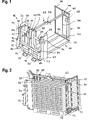
In
Das Holzbündelgerät kann ein quaderförmiges Holzbündel (siehe
Das Holzbündelgerät umfasst einen Boden
Die beiden Gabeln
Die Rückwand
Der in
Die Frontwand
Der Verriegelungsstab
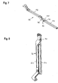
Die Quertraverse
Die Quertraverse
Das gabelförmige Ende wird durch eine Anschlagplatte
Die Rückwand
Eine Gurtspannvorrichtung
Wie zuvor bereits erläutert, hat das mobile Holzbündelgerät eine Ankoppelungseinrichtung, mit der es an einem fahrzeugseitigen Dreipunkt-Kraftheber angekoppelt werden kann. Hierzu sind drei dreiecksförmig angeordnete Koppelstellen
Nach unten offene U-förmige, an die Blechleisten
Im Folgenden wird die Funktion des erfindungsgemäßen Geräts anhand der Figuren erläutert. The function of the device according to the invention is explained below with reference to the figures.
Die
Bevorzugt wird jedoch, bevor Holz hier gebündelt wird, noch eine Palette
In diesem Zustand kann dann die Verriegelung durch Betätigen des Handgriffs an der Verriegelungsstange
Um das auf der Palette
In dieser vorne offenen, auch als Bündelentladeposition bezeichneten Stellung kann das Gerät zum Beispiel auch von einem Radlader verfahren werden. Die Gabeln
Somit sind als Ankoppelungseinrichtung nicht nur die Koppelstellen
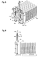
Wenn der Bediener dann ein trockenes Bündel aufnehmen und zerteilen will, baut er das Gerät in eine dritte Position (Weiterverarbeitungsposition) um, die in den
Ohne dass das Bündel aufgenommen ist, wird der Verriegelungsstift
In der in
Für die Weiterverarbeitung sind, wie in den
Nach dem Weiterverarbeiten kann die Palette mit dem Holbündelgerät, das wie ein Gabelstaplerende wirkt, auch auf einen Lkw geladen werden. Schließlich wird das Holzbündelgerät von der Palette abgezogen und kann erneut für das weitere Bündeln eingesetzt werden. After further processing, the pallet can also be loaded onto a truck with the bundle bundle device, which acts like a forklift end. Finally, the wood bundle device is removed from the pallet and can be used again for further bundling.
Das Gerät kann dann z.B. für das Bündeln schnell umgebaut werden, indem der Abschnitt
Das dargestellte Holzbündelgerät zeichnet sich auch dadurch aus, dass die vom Benutzer vorgenommenen Tätigkeiten vom Handling her sehr kräfteschonend sind, es handelt sich mehr oder weniger nur um Verriegelungs- und Entriegelungshandgriffe. Das Handling ist sehr schnell, und das Gerät ist äußerst flexibel einsetzbar. Es ist nicht nur zum Bündeln geeignet, sondern auch zum Transport der fertig bestückten Paletten und zur Weiterverarbeitung, das heißt zum Ablängen der Holzscheite über die Führungen
Die Verriegelungen sind selbstsichernd, das heißt, sie können sich nicht selbstständig öffnen, sondern benötigen eine Handbedienung oder Hydraulik. The locks are self-locking, that is, they can not open independently, but require a manual or hydraulic.
Das Holzbündelgerät ist auch sehr einfach und leicht aufgebaut, durch zahlreiche Hohlrohre, die miteinander verschweißt sind. The wood bundle device is also very simple and easy to build, by numerous hollow tubes that are welded together.
Claims (13)
Priority Applications (2)
| Application Number | Priority Date | Filing Date | Title |
|---|---|---|---|
| DE102015114993.1A DE102015114993B4 (en) | 2015-09-07 | 2015-09-07 | Mobile wood bundle device |
| ATA50770/2016A AT518156B1 (en) | 2015-09-07 | 2016-08-30 | Mobile wood bundle device |
Applications Claiming Priority (1)
| Application Number | Priority Date | Filing Date | Title |
|---|---|---|---|
| DE102015114993.1A DE102015114993B4 (en) | 2015-09-07 | 2015-09-07 | Mobile wood bundle device |
Publications (2)
| Publication Number | Publication Date |
|---|---|
| DE102015114993A1 DE102015114993A1 (en) | 2017-03-09 |
| DE102015114993B4 true DE102015114993B4 (en) | 2017-04-27 |
Family
ID=58054738
Family Applications (1)
| Application Number | Title | Priority Date | Filing Date |
|---|---|---|---|
| DE102015114993.1A Expired - Fee Related DE102015114993B4 (en) | 2015-09-07 | 2015-09-07 | Mobile wood bundle device |
Country Status (2)
| Country | Link |
|---|---|
| AT (1) | AT518156B1 (en) |
| DE (1) | DE102015114993B4 (en) |
Citations (6)
| Publication number | Priority date | Publication date | Assignee | Title |
|---|---|---|---|---|
| US3827353A (en) * | 1973-04-12 | 1974-08-06 | Yule Tree Farms | Christmas tree baling machine |
| US3889585A (en) * | 1974-05-08 | 1975-06-17 | Mac Fab Manufacturing Inc | Load-bundling and strapping apparatus |
| WO1997042085A1 (en) * | 1996-05-06 | 1997-11-13 | Psi-16 Aps | A machine and a method for compressing and packing christmas trees and the like |
| DK174723B1 (en) * | 1998-04-07 | 2003-10-06 | Lars Overgaard | Packing machine for packing Christmas trees and greenery on pallets |
| FR2881614A1 (en) * | 2005-02-07 | 2006-08-11 | Arci Rhone Alpes Ateliers De R | Billets or wood logs bundling machine for e.g. tractor, has four clamps, and power cylinder moving two clamps in two respective positions in which all four clamps define cylindrical volume for receiving billets and are spaced apart |
| AT10483U1 (en) * | 2007-03-29 | 2009-04-15 | Boehler Siegfried | DEVICE FOR STACKING, BUNNING AND / OR TRANSPORTING WOODEN PIECES |
Family Cites Families (1)
| Publication number | Priority date | Publication date | Assignee | Title |
|---|---|---|---|---|
| DE50114682D1 (en) * | 2001-03-02 | 2009-03-12 | Landrock Gmbh | Method for cutting bundled pieces of wood into pieces of wood |
-
2015
- 2015-09-07 DE DE102015114993.1A patent/DE102015114993B4/en not_active Expired - Fee Related
-
2016
- 2016-08-30 AT ATA50770/2016A patent/AT518156B1/en not_active IP Right Cessation
Patent Citations (6)
| Publication number | Priority date | Publication date | Assignee | Title |
|---|---|---|---|---|
| US3827353A (en) * | 1973-04-12 | 1974-08-06 | Yule Tree Farms | Christmas tree baling machine |
| US3889585A (en) * | 1974-05-08 | 1975-06-17 | Mac Fab Manufacturing Inc | Load-bundling and strapping apparatus |
| WO1997042085A1 (en) * | 1996-05-06 | 1997-11-13 | Psi-16 Aps | A machine and a method for compressing and packing christmas trees and the like |
| DK174723B1 (en) * | 1998-04-07 | 2003-10-06 | Lars Overgaard | Packing machine for packing Christmas trees and greenery on pallets |
| FR2881614A1 (en) * | 2005-02-07 | 2006-08-11 | Arci Rhone Alpes Ateliers De R | Billets or wood logs bundling machine for e.g. tractor, has four clamps, and power cylinder moving two clamps in two respective positions in which all four clamps define cylindrical volume for receiving billets and are spaced apart |
| AT10483U1 (en) * | 2007-03-29 | 2009-04-15 | Boehler Siegfried | DEVICE FOR STACKING, BUNNING AND / OR TRANSPORTING WOODEN PIECES |
Also Published As
| Publication number | Publication date |
|---|---|
| AT518156B1 (en) | 2019-03-15 |
| AT518156A2 (en) | 2017-07-15 |
| AT518156A3 (en) | 2019-03-15 |
| DE102015114993A1 (en) | 2017-03-09 |
Similar Documents
| Publication | Publication Date | Title |
|---|---|---|
| DE4208902C2 (en) | Bale holding device | |
| EP2905231B1 (en) | Device, system and method of manufacturing and handling bunches of stacked goods, e.g. log bunches | |
| DE1302318C2 (en) | SIDE LOADER WITH TRANSVERSIBLE LIFTING MAST | |
| DE202008005067U1 (en) | Sawhorse for cutting fireplace or kiln firewood | |
| DE3413937C2 (en) | ||
| DE1655876B2 (en) | Vehicle with loading device, in particular for transporting containers | |
| EP3272698B1 (en) | Lifting vehicle for transporting high-volume bags | |
| DE2930275A1 (en) | SELF LOADER FOR TRANSPORTATION OF LOADING UNITS | |
| EP1538092A1 (en) | Transport system | |
| DE102015114993B4 (en) | Mobile wood bundle device | |
| EP0143197A1 (en) | Arrangement for actuating a split bucket | |
| DE2947904A1 (en) | DEVICE FOR SELECTIVELY DEPOSITING TRANSPORTABLE CONTAINERS, MACHINES OR DEVICES ON THE LOADING BASE OF A TRUCK VEHICLE OR ON THE GROUND | |
| DE3841112A1 (en) | Supporting and tilting apparatus for transportable holding implements or tools, such as containers in particular and other transportation vessels | |
| AT519964B1 (en) | Packing device for press-packing trees | |
| DE10317864A1 (en) | Device for cutting pieces of wood | |
| DE102008001430A1 (en) | Device for handling firewood | |
| DE2660637C2 (en) | TRANSPORT DEVICE, CONSISING OF A REMOVABLE CONTAINER AND A TRANSPORT VEHICLE | |
| AT523849B1 (en) | trailer for a motor vehicle | |
| DE102012014523A1 (en) | Load handling vehicle i.e. reach stacker, for stacking and handling transport containers, has fastening device comprising engaging projection, which is positive-lockingly fixed in engaged state that engages in one of retainers | |
| DE3139141A1 (en) | Transportation vehicle | |
| DE2535495A1 (en) | DEVICE FOR HANDLING AND TRANSPORTING PALLETS OR PALLET CONTAINERS | |
| DE202016004454U1 (en) | Lift truck for transporting large volume bags | |
| DE202011100212U1 (en) | Trailers, in particular for the transport of wood | |
| WO1998038115A1 (en) | Supporting device for containers or the like | |
| DE102020006686A1 (en) | Standing log splitter |
Legal Events
| Date | Code | Title | Description |
|---|---|---|---|
| R012 | Request for examination validly filed | ||
| R016 | Response to examination communication | ||
| R018 | Grant decision by examination section/examining division | ||
| R020 | Patent grant now final | ||
| R119 | Application deemed withdrawn, or ip right lapsed, due to non-payment of renewal fee |