EP0143197A1 - Arrangement for actuating a split bucket - Google Patents
Arrangement for actuating a split bucket Download PDFInfo
- Publication number
- EP0143197A1 EP0143197A1 EP84110176A EP84110176A EP0143197A1 EP 0143197 A1 EP0143197 A1 EP 0143197A1 EP 84110176 A EP84110176 A EP 84110176A EP 84110176 A EP84110176 A EP 84110176A EP 0143197 A1 EP0143197 A1 EP 0143197A1
- Authority
- EP
- European Patent Office
- Prior art keywords
- arrangement according
- hooks
- shells
- hook
- container
- Prior art date
- Legal status (The legal status is an assumption and is not a legal conclusion. Google has not performed a legal analysis and makes no representation as to the accuracy of the status listed.)
- Granted
Links
- 239000000725 suspension Substances 0.000 claims abstract description 16
- 238000006073 displacement reaction Methods 0.000 description 4
- 230000005540 biological transmission Effects 0.000 description 1
- 230000015572 biosynthetic process Effects 0.000 description 1
- 230000000295 complement effect Effects 0.000 description 1
- 238000010276 construction Methods 0.000 description 1
- 239000011521 glass Substances 0.000 description 1
- 238000003780 insertion Methods 0.000 description 1
- 230000037431 insertion Effects 0.000 description 1
- 239000010893 paper waste Substances 0.000 description 1
- 230000002028 premature Effects 0.000 description 1
- 239000002699 waste material Substances 0.000 description 1
Images


Classifications
-
- B—PERFORMING OPERATIONS; TRANSPORTING
- B66—HOISTING; LIFTING; HAULING
- B66C—CRANES; LOAD-ENGAGING ELEMENTS OR DEVICES FOR CRANES, CAPSTANS, WINCHES, OR TACKLES
- B66C3/00—Load-engaging elements or devices attached to lifting or lowering gear of cranes or adapted for connection therewith and intended primarily for transmitting lifting forces to loose materials; Grabs
- B66C3/14—Grabs opened or closed by driving motors thereon
- B66C3/16—Grabs opened or closed by driving motors thereon by fluid motors
-
- B—PERFORMING OPERATIONS; TRANSPORTING
- B65—CONVEYING; PACKING; STORING; HANDLING THIN OR FILAMENTARY MATERIAL
- B65F—GATHERING OR REMOVAL OF DOMESTIC OR LIKE REFUSE
- B65F1/00—Refuse receptacles; Accessories therefor
- B65F1/12—Refuse receptacles; Accessories therefor with devices facilitating emptying
- B65F1/125—Features allowing the receptacle to be lifted and emptied by its bottom
-
- E—FIXED CONSTRUCTIONS
- E02—HYDRAULIC ENGINEERING; FOUNDATIONS; SOIL SHIFTING
- E02F—DREDGING; SOIL-SHIFTING
- E02F3/00—Dredgers; Soil-shifting machines
- E02F3/04—Dredgers; Soil-shifting machines mechanically-driven
- E02F3/28—Dredgers; Soil-shifting machines mechanically-driven with digging tools mounted on a dipper- or bucket-arm, i.e. there is either one arm or a pair of arms, e.g. dippers, buckets
- E02F3/36—Component parts
- E02F3/40—Dippers; Buckets ; Grab devices, e.g. manufacturing processes for buckets, form, geometry or material of buckets
- E02F3/413—Dippers; Buckets ; Grab devices, e.g. manufacturing processes for buckets, form, geometry or material of buckets with grabbing device
- E02F3/4135—Dippers; Buckets ; Grab devices, e.g. manufacturing processes for buckets, form, geometry or material of buckets with grabbing device with grabs mounted directly on a boom
Definitions
- the invention makes use of an arrangement for attaching and opening a folding container with a hanging crossbar to be arranged on a crane boom or the like, which has hydraulically actuated hooks projecting downwards, and with hooking elements on the two half-shells of the folding container, which are arranged on the top along a pivot axis are hinged together.
- the hanging crosshead has three hydraulically actuated hooks, of which the middle one is designed as a load hook that supports the folding container on a hooking element that is arranged in the region of the pivot axis of the two container half-shells, while the other two hooks with hooking elements on the lateral outer walls of the container half-shells can be brought into engagement, the two container half-shells being able to be opened apart by vertical displacement of the middle support hook relative to the external hooks.
- the hanging cross member is complex and must extend with its separate, external hooks over the entire width of the folding container. Furthermore, when hooking up the folding container, three hooks must be brought into engagement with the corresponding hooking elements on the container, for which purpose the suspension crossmember must be guided by hand. In addition, they are on the sides of the outside walls of the container lying hook elements disturbing.
- the known arrangements are not suitable for disposal containers which are to be set up as collection containers for paper, waste glass or the like at collection points and are to be emptied on the spot into a large-capacity container of a disposal vehicle which has a corresponding crane device on which the suspension cross member is to be arranged .
- disposal containers have to be kept free of disruptive projections on the side, and on the other hand, it must be possible to attach and empty the folding container into the spacecraft vehicle without using the hanging crossbar, which is why the hooks on the hanging crossbar can be easily threaded into the corresponding hook elements - the container half-shells should be aimed at from above.
- the invention is therefore based on the object of improving an arrangement of the type mentioned at the outset in that, with only two hooks of the hanging crossbar acting from above, the container is first lifted closed and then its half-shells can be unfolded.
- the hanging cross member has two horizontally displaceable hooks with upward hook openings and the hooking elements are arranged on the top of the half-shells so that their connecting line lies horizontally above the pivot axis of the half-shells and at a distance therefrom.
- the particular advantage of an arrangement according to the invention is that the hanging crossbar attached to a crane boom can be coupled by a single operator without manual intervention on the upper hooking elements of the container shells and, after being raised by a horizontal movement of the two hooks, unfolded towards one another to form the two half-shells of the container can be.
- the container half-shells fold back in the opposite direction of movement of the hooks of the hanging crossbar.
- the container can be set down in this arrangement and then, after the hooks have been lowered so far that the hooking elements have come free from the hook openings, the hooks can be moved in the opposite direction of movement to such an extent that the traverse can be raised without having to use the hooks again to come into engagement with the hooking elements.
- guide webs can be provided on the top of the container half-shells, between which the hooking elements are expediently designed as bolts.
- the hooks are arranged on carriages, which are displaceable between two horizontal supports of the suspension crossmember, on which the carriages are guided by rollers.
- a hydraulic cylinder is advantageously arranged, which on the one hand has the end of its piston rod and the end of its cylinder jacket on the other hand, is connected crosswise by the slides to the hooks projecting on the underside of the horizontal beams.
- the slides which are therefore designed in opposite directions, also allow a short overall length of the suspension crossmember, which is important for a large opening angle of the half-shells of the container.
- each slide is also positioned so that the moments resulting from the load attached to the hook and the pressure from the cylinder are directed in opposite directions.
- the construction of the suspension crossmember is also of particular advantage, because the two slides, which are mounted on the horizontal supports, in a preferred embodiment consist of identical parts which are mounted on the horizontal supports, reversed from one another.
- the extended end position of the hooks corresponds to the receiving width of the hooking elements, which means that the hooks have to be brought into engagement with the hooking elements from the inside with outwardly directed hook projections, but on the other hand prevents that when lifting the hooking elements Container is a force pulling the hooking elements is applied, which could lead to premature opening of the half-shells.
- FIG. 1 shows a folding container 1 which is divided into two half-shells 2 along a vertical center plane.
- the two half-shells 2 are connected to one another at their upper sides via joints 3 in such a way that their bottoms and side walls can be folded apart.
- the two half-shells pivot about the axis A, which is the axis of the joints 3.
- This axis A runs in the transverse or depth direction of the container 1 in the middle on its upper side. It goes without saying that the container 1 has an essentially cubic or cuboid shape.
- the half-shells 2 Symmetrical to the parting plane of the container 1, the half-shells 2 have hooking elements 4 on their upper side, which, as FIG. 4 in particular shows, each consist of a bolt 25, which is parallel to the pivot axis A.
- the half-shells 2 On the upper sides of the half-shells 2 there are webs 5 which run essentially in the diagonal direction to the top of the container and which diverge inwards towards the pivot axis A.
- the hooking pin 25 lies in the area of the smallest distance between the two webs 5.
- hooking elements 4 are always arranged independently of the spread position of the container half-shells 2 so that the horizontal plane in which they lie is at a distance from the horizontally lying pivot axis A. Because of this distance, a pivoting moment with respect to the pivot axis A results for each of the container shells 2 when the two hooking elements 4 on the top sides of the half shells 2 are pressed together in the horizontal direction.
- a hanging cross member 6, the basic structure of which can be seen in FIGS. 1 and 2, is used to attach and open the container 1. It has two horizontal supports 7 lying next to one another, which will be discussed in more detail below with reference to FIG. 3. On these horizontal supports 7, two hooks 8 are arranged so as to be displaceable in the longitudinal direction of the supports 7.
- a hydraulic cylinder 9 is seated on the supports 7, which with its piston rod 11 on the left in FIG. 1 with the hook 8 on the right in this figure and with the end of its cylinder jacket 10 which is arranged to the right with the hook 8 on the left connected is.
- the hooks 8 are in the extended end position of the cylinder 9 are in their retracted, nearest end position, as shown in FIG. 1, while, in accordance with FIG. 2, in the retracted end position of the cylinder 9, the hooks 8 have moved the farthest apart.
- the hydraulic cylinder 10 is a differential cylinder, and the working direction of the cylinder 10, in which the greater lifting force can be applied, is associated with the movement of the hooks 8 together, so that the greater cylinder force is available when the two containers -Shells 2 to be opened.
- the hooks 8 each have hook openings 14 lying upwards, which are correspondingly delimited by hook projections 15 lying outwards.
- the hooks 8, which are almost flush with one another in the longitudinal direction of the horizontal supports 7, must first be lowered with their hook projections 15 to below the bolts 25 of the hooking elements 4 when the container is attached, the hooks 8 initially being slightly moved together. Then the hooks 8 are moved apart via the hydraulic cylinder 9 to an end stop, after which the hook openings 14 are aligned in the vertical direction with the bolts 25 of the hooking elements 4 on the half-shells 2. In this position, the entire container 1 can first be lifted without the half-shells 2 being unfolded, the bolts 25 of the hooking elements 4 coming into engagement with the hooks 8 without transmission of a horizontal force.
- the threading of the hooks 8 into the hooking devices 4 facilitate the diverging webs 5 on the top of the container half-shells 2, as shown in FIG. If, as in the exemplary embodiment, the hooks 8 are inserted into the hooking devices 4 from the inside, it is advantageous if the webs 5 diverge inwards, ie towards the pivot axis A, in order to form a funnel-shaped insertion opening 26.
- the two webs 5 still have a distance which is somewhat larger than the thickness of the hooks 8, so that on the one hand the hooks 8 in the engaged position essentially on the vertical Center plane of the container 1 are aligned and, on the other hand, enough play is available for easy threading of the hooks 8 into the hooking elements 4.
- the suspension crossmember 6 hangs on a rotary drive 12, via which the suspension crossmember 6 can be pivoted about a vertical axis.
- the rotary drive 12 also makes it possible to be able to rotate the container 1 hanging on the hanging cross member 6 after lifting.
- the suspension crossmember 6 with the rotary drive 12 hangs on a crane boom 13, which is preferably constructed on the chassis of a large container vehicle, in the container of which the respective folding container 1 is to be emptied.
- Figure 3 illustrates the load-bearing parts of the suspension cross member 6.
- Die Hooks 8 are in each case parts of two slides 16 which are mounted on the horizontal supports 7 so as to be displaceable relative to one another.
- the carriages 16 are each flat rails, at one end of which the hooks 8 are arranged projecting downward and are additionally supported by struts 24 running diagonally. At the other end, the carriages 16 have a plate 27 or another force-absorbing element, on which the hydraulic cylinder 9 engages.
- the hydraulic cylinder 9 is freely suspended, so it is supported only on the two slides 16.
- the two carriages 16 are identical flat parts, which are arranged reversely to one another and with their respective inner sides lie slidingly against one another.
- This unit consisting of the two complementary slides 16 is arranged between the two horizontal supports 7, which consist of two U-profiles that are mutually spaced apart with their flanges.
- the slides 16 On their outer sides, the slides 16 have laterally protruding axle journals 17, on which rollers 18 are placed, each of which engages in the U-beam 7.
- the carriages 16 On their inner sides, the carriages 16 have further journals 19 and 20, which are longer than the outer journals 17 by the thickness of the flat part which forms the carriages 16.
- the pin 19 lying on the hook end also serves as a guide pin and, in an assembled arrangement, engages through an elongated hole 23, which is in each case in the longitudinal direction of the slide 16.
- On the protruding end is on the guide pin 19th also a roller 21 is mounted, which engages in alignment with the rollers 18 in the direction of displacement of the hooks 8 in the U-shaped carrier 7.
- the length of the elongated hole 23 corresponds at least to the displacement length of the hooks 8 relative to one another.
- the pin 20 located at the end of the attack of the hydraulic cylinder 9 engages in the direction of displacement next to the other slide 16 and into the opposite horizontal support 7 and carries a further roller 22 guided therein. As already mentioned, this applies mutually to each of the two slides 16 to.
Abstract
Description
Die Erfindung bedient sich auf eine Anordnung zum Anhängen und Aufklappen eines Klappbehälters mit einer an einem Kranausleger oder dergleichen anzuordnenden Hängetraverse, die nach unten vorstehende, hydraulisch betätigte Haken hat, und mit Einhakelementen an den beiden Halbschalen des Klappbehälters, die an dessen Oberseite längs einer Schwenkachse miteinander gelenkig verbunden sind.The invention makes use of an arrangement for attaching and opening a folding container with a hanging crossbar to be arranged on a crane boom or the like, which has hydraulically actuated hooks projecting downwards, and with hooking elements on the two half-shells of the folding container, which are arranged on the top along a pivot axis are hinged together.
Eine Anordnung der genannten Art ist aus der deutschen Offenlegungsschrift 25 21 021 bekannt. Dort besitzt die Hängetraverse drei hydraulisch betätigbare Haken, von denen der mittlere als Lasthaken ausgebildet ist, der den Klappbehälter an einem Einhakelement trägt, das im Bereich der Schwenkachse der beiden Behälter-Halbschalen angeordnet ist, während die beiden weiteren Haken mit Einhakelementen an den seitlichen Außenwandungen der Behälter-Halbschalen in Eingriff gebracht werden können, wobei durch Vertikalverschiebung des mittleren Traghakens gegenüber den außen liegenden Haken die beiden Behälter-Halbschalen auseinandergeklappt werden können. Bei dieser bekannten Anordnung ist die Hängetraverse aufwendig ausgebildet und muß mit ihren separaten, außen liegenden Haken über die gesamte Breite des Klappbehälters reichen. Ferner müssen beim Anhängen des Klappbehälters drei Haken in Eingriff mit den entsprechenden Einhakelementen am Behälter gebracht werden, wozu die Hängetraverse von Hand geführt werden muß. Außerdem sind die seitlich an den Außenwandungen des Behälters liegenden Einhakelemente störend.An arrangement of the type mentioned is known from German Offenlegungsschrift 25 21 021. There, the hanging crosshead has three hydraulically actuated hooks, of which the middle one is designed as a load hook that supports the folding container on a hooking element that is arranged in the region of the pivot axis of the two container half-shells, while the other two hooks with hooking elements on the lateral outer walls of the container half-shells can be brought into engagement, the two container half-shells being able to be opened apart by vertical displacement of the middle support hook relative to the external hooks. In this known arrangement, the hanging cross member is complex and must extend with its separate, external hooks over the entire width of the folding container. Furthermore, when hooking up the folding container, three hooks must be brought into engagement with the corresponding hooking elements on the container, for which purpose the suspension crossmember must be guided by hand. In addition, they are on the sides of the outside walls of the container lying hook elements disturbing.
Eine andere Anordnung zum Anhängen und Aufklappen eines Klappbehälters ist aus der Europa-Offenlegungsschrift 54 463 bekannt. Dort sind allerdings am Klappbehälter selbst Hydraulikzylinder angeordnet, um die klappbaren Seitenwandungen des Behälters zu betätigen.Another arrangement for attaching and opening a folding container is known from the European patent application 54 463. There, however, hydraulic cylinders are arranged on the folding container itself in order to actuate the foldable side walls of the container.
Die bekannten Anordnungen sind nicht für solche Entsorgungsbehälter geeignet, die als Sammelbehälter für Papier, Altglas oder dergleichen an Sammelstellen aufgestellt und an Ort und Stelle in einen Großraumbehälter eines Entsorgungsfahrzeugs entleert werden sollen, das über eine entsprechende Kranvorrichtung, an der die Hängetraverse anzuordnen ist, verfügt. Zum einen sind solche Entsorgungsbehälter seitlich frei von störenden Vorsprüngen zu halten und zum anderen muß das Anhängen und Entleeren des Klappbehälters in das Graßraumfahrzeug hinein ohne Einsatz von Hand über die Hängetraverse möglich sein, weswegen eine leichte Einfädelung der Haken an der Hängetraverse in die entsprechenden Hakenelemente an-den Behälter-Halbschalen von oben her anzustreben ist.The known arrangements are not suitable for disposal containers which are to be set up as collection containers for paper, waste glass or the like at collection points and are to be emptied on the spot into a large-capacity container of a disposal vehicle which has a corresponding crane device on which the suspension cross member is to be arranged . On the one hand, such disposal containers have to be kept free of disruptive projections on the side, and on the other hand, it must be possible to attach and empty the folding container into the spacecraft vehicle without using the hanging crossbar, which is why the hooks on the hanging crossbar can be easily threaded into the corresponding hook elements - the container half-shells should be aimed at from above.
Deshalb liegt der Erfindung die Aufgabe zugrunde, eine Anordnung der eingangs genannten Art .dadurch zu verbessern, daß mit nur lediglich zwei von oben her angreifenden Haken der Hängetraverse der Behälter zunächst geschlossen angehoben und danach dessen Halbschalen auseinandergeklappt werden können.The invention is therefore based on the object of improving an arrangement of the type mentioned at the outset in that, with only two hooks of the hanging crossbar acting from above, the container is first lifted closed and then its half-shells can be unfolded.
Diese Aufgabe wird bei einer Anordnung der gattungsgemäßen Art nach der Erfindung dadurch gelöst, daß die Hängetraverse zwei horizontal zueinander verschiebliche Haken mit nach oben hin liegenden Hakenöffnungen hat und die Einhakelemente oberseitig an den Halbschalen so angeordnet sind, daß ihre Verbindungslinie horizontal oberhalb der Schwenkachse der Halbschalen sowie in Abstand davon liegt.This task is done with an arrangement of Generic type according to the invention in that the hanging cross member has two horizontally displaceable hooks with upward hook openings and the hooking elements are arranged on the top of the half-shells so that their connecting line lies horizontally above the pivot axis of the half-shells and at a distance therefrom.
Der besondere Vorteil einer erfindungsgemäßen Anordnung liegt darin, daß die an einem Kranausleger angebrachte Hängetraverse von einer einzigen Bedienungsperson ohne manuellen Eingriff an den oberseitigen Einhakelementen der Behälterschalen angekuppelt werden kann und nach dem Anheben durch eine Horizontalbewegung der beiden Haken aufeinander zu die beiden Halbschalen des Behälters auseinandergeklappt werden können. In entgegengesetzter Bewegungsrichtung der Haken der Hängetraverse klappen die Behälter-Halbschalen wieder zusammen. Der Behälter kann in dieser Anordnung abgesetzt werden und anschließend können, nachdem die Haken soweit abgesenkt sind, daß die Einhakelemente aus den Hakenöffnungen freigekommen sind, die Haken in entgegengesetzter Bewegungsrichtung so weit verfahren werden, daß die Anhängetraverse angehoben werden kann, ohne erneut mit den Haken in Eingriff mit den Einhakelementen zu kommen. Um die Haken besonders leicht in Richtung zu den Einhakelementen einfädeln zu können, können auf der Oberseite der Behälter-Halbschalen Führungsstege vorgesehen sein, zwischen denen zweckmäßig die Einhakelemente als Bolzen ausgebildet sind.The particular advantage of an arrangement according to the invention is that the hanging crossbar attached to a crane boom can be coupled by a single operator without manual intervention on the upper hooking elements of the container shells and, after being raised by a horizontal movement of the two hooks, unfolded towards one another to form the two half-shells of the container can be. The container half-shells fold back in the opposite direction of movement of the hooks of the hanging crossbar. The container can be set down in this arrangement and then, after the hooks have been lowered so far that the hooking elements have come free from the hook openings, the hooks can be moved in the opposite direction of movement to such an extent that the traverse can be raised without having to use the hooks again to come into engagement with the hooking elements. In order to be able to thread the hooks particularly easily in the direction of the hooking elements, guide webs can be provided on the top of the container half-shells, between which the hooking elements are expediently designed as bolts.
In vorteilhafter Ausbildung sind die Haken an Schlitten angeordnet, welche zwischen zwei Horizontalträgern der Hängetraverse, an denen die Schlitten mittels Rollen geführt sind, verschieblich sind, Oberhalb der Horizontalträger ist vorteilhaft ein Hydraulizylinder angeordnet, der mit dem Ende seiner Kolbenstange einerseits und dem Ende seines Zylindermantels andererseits durch die Schiitten überkreuz mit den unterseitig an den Horizontalträgern vorstehenden Haken verbunden ist. Die deshalb gegenläufig ausgebildeten Schlitten ermöglichen zudem eine kurze Baulänge der Hängetraverse, die für einen großen öffnungswinkel der Halbschalen des Behälters wichtig ist.In an advantageous embodiment, the hooks are arranged on carriages, which are displaceable between two horizontal supports of the suspension crossmember, on which the carriages are guided by rollers. Above the horizontal supports, a hydraulic cylinder is advantageously arranged, which on the one hand has the end of its piston rod and the end of its cylinder jacket on the other hand, is connected crosswise by the slides to the hooks projecting on the underside of the horizontal beams. The slides, which are therefore designed in opposite directions, also allow a short overall length of the suspension crossmember, which is important for a large opening angle of the half-shells of the container.
Auch ist die Hauptlagerachse jedes Schlittens so gelegt, daß die sich einerseits durch die an den Haken angehängte Last und andererseits durch die Druckbeaufschlagung des Zylinders ergebenden Momente einander entgegengesetzt gerichtet sind. Dadurch können trotz der hohen auftretenden Kräfte für die Schlitten Gleitlager verwendet werden, ohne daß bei Belastung ein Verklemmen auftreten kann.The main bearing axis of each slide is also positioned so that the moments resulting from the load attached to the hook and the pressure from the cylinder are directed in opposite directions. As a result, slide bearings can be used in spite of the high forces that occur for the slide, without jamming occurring under load.
Von besonderem Vorteil ist ferner der Aufbau der Hängetraverse, denn die beiden Schlitten, die an den Horizontalträgern gelagert sind, bestehen in bevorzugter Ausführung aus identischen Teilen, die seitenverkehrt zueinander an den Horizontalträgern gelagert sind.The construction of the suspension crossmember is also of particular advantage, because the two slides, which are mounted on the horizontal supports, in a preferred embodiment consist of identical parts which are mounted on the horizontal supports, reversed from one another.
Auch ist es von Vorteil, an der Hängetraverse einen Differentialzylinder verwenden zu können, wobei die Bewegungsrichtung, in der die größere Kraft aufgebracht werden kann, der Spreizbewegung der Halbschalen des Klappbehälters zugeordnet ist. Das ist besonders vorteilhaft, wenn wie bei Behältern zum Sammeln von Altpapier größere Spreizkräfte aufgebracht werden müssen, weil zwischen dem im Behälter sich verdichtenden Papierballen und den Wandungen der spreizbaren Halbschalen große Reibungskräfte auftreten können.It is also advantageous to be able to use a differential cylinder on the suspension crossmember, the direction of movement being the larger one Force can be applied to the spreading movement of the half-shells of the folding container. This is particularly advantageous when, as with containers for collecting waste paper, greater spreading forces have to be applied because large frictional forces can occur between the paper bale that is compacting in the container and the walls of the expandable half-shells.
Ferner ist von Vorteil, wenn die auseinandergeschobene Endstellung der Haken der Aufnahmeweite der Einhakelemente entspricht, was bedingt, daß die Haken zwar von innen her mit nach außen gerichteten Hakenvorsprüngen in Eingriff mit den Einhakelementen gebracht werden müssen, andererseits aber verhindert, daß schon beim Anheben des Behälters eine die Einhakelemente zusammenziehende Kraft aufgebracht ist, die zu einem vorzeitigen Aufklappen der Halbschalen führen könnte.It is also advantageous if the extended end position of the hooks corresponds to the receiving width of the hooking elements, which means that the hooks have to be brought into engagement with the hooking elements from the inside with outwardly directed hook projections, but on the other hand prevents that when lifting the hooking elements Container is a force pulling the hooking elements is applied, which could lead to premature opening of the half-shells.
Weitere vorteilhafte Ausgestaltungsmerkmale der Erfindung ergeben sich aus den Unteransprüchen und aus der nachstehenden Beschreibung.Further advantageous design features of the invention result from the subclaims and from the description below.
Die Erfindung wird nachfolgend anhand der Zeichnung an einem Ausführungsbeispiel näher erläutert. Dabei zeigen:
- Fig. 1 eine Seitansicht eines an einer Hängetraverse angeordneten Klappbehälters,
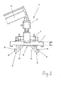
- Fig. 2 in vergrößerter Darstellung die Ansicht der Hängetraverse nach Fig. 1,
- Fig. 3 in gesprengter perspektivischer Darstellung die Ausbildung der Führungsträger und der Hakenschlitten der Hängetravers nach den Fig. 1 und 2 und
- Fig. 4 die Draufsicht auf den Klappbehälter gem. Fig. 1.
- 1 is a side view of a folding container arranged on a hanging cross member,
- 2 is an enlarged view of the suspension crossmember of FIG. 1,
- Fig. 3 in an exploded perspective view, the formation of the guide carrier and the hook sled of the hanging traverse according to FIGS. 1 and 2 and
- Fig. 4 according to the top view of the folding container. Fig. 1.
Figur 1 zeigt einen Klappbehälter 1, der längs einer vertikalen Mittenebene in zwei Halbschalen 2 unterteilt ist. Die beiden Halbschalen 2 sind an ihren Oberseiten über Gelenke 3 derart miteinander verbunden, daß sich deren Böden und Seitenwandungen auseinanderklappen lassen. Dabei schwenken die beiden Halbschalen um die Achse A, welches die Achse der Gelenke 3 ist. Diese Achse A verläuft in Quer- oder Tiefenrichtung des Behälters 1 mittig an dessen Oberseite. Dabei versteht sich, daß der Behälter 1 eine im wesentlichen kubische oder quaderförmige Gestalt hat.FIG. 1 shows a
Symmetrisch zur Teilungsebene des Behälters 1 besitzen die Halbschalen 2 an ihrer Oberseite Einhakelemente 4, die, wie Figur 4 insbesondere zeigt, aus jeweils einem Bolzen 25 bestehen, der parallel zur Schwenkachse A liegt. An den Oberseiten der Halbschalen 2 sind im wesentlichen in Diagonalrichtung zur Behälteroberseite verlaufende Stege 5 angeordnet, die nach innen hin zur Schwenkachse A wieder auseinanderlaufen. Im Bereich des geringsten Abstandes der jeweils beiden Stege 5 liegt der Einhakbolzen 25.Symmetrical to the parting plane of the
Diese Einhakelemente 4 sind unabhängig von der Spreizstellung der Behälter-Halbschalen 2 immer so angeordnet, daß die Horizontalebene, in der sie liegen, einen Abstand zu der horizontal liegenden Schwenkachse A hat. Aufgrund dieses Abstandes ergibt sich für jede der Behälterschalen 2 ein Schwenkmoment bezogen auf die Schwenkachse A, wenn die beiden Einhakelemente 4 an den Oberseiten der Halbschalen 2 in Horizontalrichtung zusammengedrückt werden.These hooking
Zum Anhängen und Aufklappen des Behälters 1 dient eine Hängetraverse 6, deren grundsätzlicher Aufbau in den Figuren 1 und 2 zu erkennen ist. Sie besitzt zwei nebeneinander liegende Horizontalträger 7, auf die in bezug auf Figur 3 nachstehend noch näher eingegangen wird. An diesen Horizontalträgern 7 sind zwei Haken 8 in Längsrichtung der Träger 7 relativ zueinander verschieblich angeordnet. Dazu sitzt auf den Trägern 7 ein Hydraulikzylinder 9, der mit seiner in Figur 1 links liegenden Kolbenstange 11 mit dem in dieser Figur rechts liegenden Haken 8 und mit dem Ende seines Zylindermantels 10, das nach rechts hin angeordnet ist, mit dem links liegenden Haken 8 verbunden ist. Es versteht sich dabei, daß in ausgefahrener Endstellung des Zylinders 9 sich die Haken 8 in ihrer zusammengefahrenen, nächstliegenden Endstellung befinden, was Figur 1 zeigt, während entsprechend Figur 2 in eingefahrener Endstellung des Zylinders 9 die Haken 8 am weitesten auseinandergefahren sind.A
Bei dem Hydraulikzylinder 10 handelt es sich um einen Differenzialzylinder, und es ist die Arbeitsrichtung des Zylinders 10, in der die größere Hubkraft aufgebracht werden kann, der Zusammenfahrbewegung der Haken 8 zugeordnet, womit die größere Zylinderkraft also dann zur Verfügung steht, wenn die beiden Behälter-Halbschalen 2 aufgeklappt werden sollen.The
Wie Figur 2 weiter zeigt, besitzen die Haken 8 jeweils nach oben hin liegende Hakenöffnungen 14, die entsprechend durch nach außen hin liegende Hakenvorsprünge 15 begrenzt sind. Die in Längsrichtung der Horizontalträger 7 fast fluchtend zueinander liegenden Haken 8 müssen beim Anhängen des Behälters zunächst mit ihren Hakenvorsprüngen 15 bis unter die Bolzen 25 der Einhakelemente 4 abgesenkt werden, wobei zunächst die Haken 8 etwas zusammengerückt sind. Danach werden die Haken 8 über den Hydraulikzylinder 9 bis zu einem Endanschlag auseinandergefahren, wonach in Vertikalrichtung die Hakenöffnungen 14 mit den Bolzen 25 der Einhakelemente 4 an den Halbschalen 2 fluchten. In dieser Position kann der gesamte Behälter 1 zunächst angehoben werden, ohne daß die Halbschalen 2 auseinandergeklappt werden, wobei die Bolzen 25 der Einhakelemente 4 mit den Haken 8 ohne Übertragung einer Horizontalkraft in Eingriff kommen.As FIG. 2 further shows, the
Das Einfädeln der Haken 8 in die Einhakvorrichtungen 4 erleichtern die divergierenden Stege 5 an der Oberseite der Behälter-Halbschalen 2, was Figur 4 zeigt. Wenn wie beim Ausführungsbeispiel die Haken 8 von innen her in die Einhakvorrichtungen 4 eingefahren werden, ist es von Vorteil, wenn nach innen, also zur Schwenkachse A hin, die Stege 5 auseinanderlaufen, um eine trichterförmige Einführöffnung 26 zu bilden. An der engsten Stelle zwischen den jeweils beiden Stegen 5, an der der Bolzen 25 liegt, haben die beiden Stege 5 noch einen Abstand der etwas größer als die Dicke der Haken 8 ist, so daß einerseits die Haken 8 in Eingriffstellung im wesentlichen auf die vertikale Mittenebene des Behälters 1 ausgerichtet sind und andererseits zum leichten Einfädeln der Haken 8 in die Einhakelemente 4 genügend Spiel zur Verfügung steht.The threading of the
Um ein Ausrichten der gesamten Hängetraverse 6 quer zur Teilungsebene des Klappbehälters 1 ohne Einsatz von Hand zu ermöglichen, hängt die Hängetraverse 6 an einem Drehantrieb 12, über den die Hängetraverse 6 um eine vertikale Achse schwenkbar ist. Der Drehantrieb 12 ermöglicht es ferner, den an der Hängetraverse 6 hängenden Behälter 1 nach dem Anheben beliebig verdrehen zu können. Die Hängetraverse 6 mit dem Drehantrieb 12 hängt an einem Kranausleger 13, der vorzugsweise auf dem Fahrgestell eines Großbehälter-Fahrzeugs aufgebaut ist, in dessen Behälter der jeweilige Klappbehälter 1 zu entleeren ist.In order to enable alignment of the
In Ergänzung zu Figur 2 veranschaulicht Figur 3 die tragenden Teile der Hängetraverse 6. Die Haken 8 sind jeweils Teile zweier Schlitten 16, die gegeneinander verschieblich an den Horizontalträgern 7 gelagert sind. Dabei handelt es sich bei den Schlitten 16 jeweils um Flachschienen, an deren einen Ende nach unten vorstehend die Haken 8 angeordnet sind und zusätzlich noch über dagonal verlaufende Streben 24 abgestützt sind. An dem jeweils anderen Ende besitzen die Schlitten 16 eine Platte 27 oder ein anderes kraftaufnehmendes Element, an dem jeweils der Hydraulikzylinder 9 angreift.In addition to Figure 2, Figure 3 illustrates the load-bearing parts of the
Im übrigen ist der Hydraulikzylinder 9 frei aufgehängt, er stützt sich also nur an den beiden Schlitten 16 ab. Bei den beiden Schlitten 16 handelt es sich um identische Flachteile, die seitenverkehrt zueinander angeordnet sind und mit ihren jeweiligen Innenseiten gleitend anein-.. ander liegen. Diese Einheit aus den beiden sich ergänzenden Schlitten 16 ist zwischen den beiden Horizontalträgern 7 angeordnet, die aus zwei mit ihren Flanschen zueinander gekehrten, in Abstand voneinander liegenden U-Profilen bestehen. An ihren Außenseiten besitzen die Schlitten 16 seitlich vorstehende Achszapfen 17, auf die Rollen 18 aufgesetzt sind, welche jeweils in die U-Träger 7 eingreifen. An ihren Innenseiten haben die Schlitten 16 weitere Achszapfen 19 und 20, die um die Dicke des Flachteils das die Schlitten 16 bildet, länger als die äußeren Achszapfen 17 sind. Der am Hakenende liegende Zapfen 19 dient zugleich als Führungszapfen und greift in zusammengefügter Anordnung durch ein Langloch 23, das jeweils in Längsrichtung der Schlitten 16 liegt, hindurch. Auf dem überstehenden Ende ist auf dem Führungszapfen 19 ebenfalls eine Rolle 21 gelagert, die fluchtend mit den Rollen 18 in Verschieberichtung der Haken 8 in die U-förmigen Träger 7 eingreift. Es vesteht sich, daß die Länge des Langlochs 23 zumindest der Verschiebelänge der Haken 8 relativ zueinander entspricht. Der am Angriffsende des Hydraulikzylinders 9 jeweils liegende Zapfen 20 greift in Verschieberichtung neben dem jeweils anderen Schlitten 16 vorbei bis in den gegenüberliegenden Horizontalträger 7 ein und trägt eine weitere, darin geführte Rolle 22. Dies trifft, wie schon gesagt, wechselseitig für jeden der beiden Schlitten 16 zu.In addition, the
Bei Belastung der Haken 8 versucht die Anhängelast, den jeweiligen Schlitten 16 um den Lagerzapfen 17 zu drehen. Der an der Platte 27 angreifende Hydraulikzylinder 9 übt auf den Schlitten 16 bezogen auf den Achszapfen 17 ein entgegengesetzt gerichtetes Drehmoment aus. Dadurch werden die zueinander relativ verschieblichen Schlitten 16 stabilisiert, insbesondere wird eine hohe Flächenpressung zwischen dem Führungszapfen 19 und dem jeweiligen Langloch 23 vermieden, wodurch insgesamt ein Verklemmen der gegeneinander beweglichen Schlitten 16 verhindert ist.When the
Claims (15)
dadurch gekennzeichnet, daß die Hängetraverse (6) zwei horizontal zueinander verschiebliche Haken (8) mit nach oben hin liegenden Hakenöffnungen (14) hat und die Einhakelemente (4) oberseitig an den Halbschalen (2) so angeordnet sind, daß ihre Verbindungslinie horizontal oberhalb der Schwenkachse (A) der Halbschalen (2) sowie in Abstand davon liegt.1. Arrangement for attaching and unfolding a folding container with a hanging crossbar to be arranged on a crane boom or the like, which has hydraulically operated hooks projecting downwards, and with hooking elements on the two half-shells of the folding container, which are hingedly connected to one another along a pivot axis at the top thereof ,
characterized in that the hanging crossmember (6) has two horizontally displaceable hooks (8) with hook openings (14) lying upwards and the hooking elements (4) on the top side of the half-shells (2) are arranged such that their connecting line is horizontal above the Swivel axis (A) of the half-shells (2) and at a distance from it.
Priority Applications (1)
| Application Number | Priority Date | Filing Date | Title |
|---|---|---|---|
| AT84110176T ATE25370T1 (en) | 1983-09-01 | 1984-08-27 | ARRANGEMENT FOR ACTIVATING A FOLDABLE CONTAINER. |
Applications Claiming Priority (2)
| Application Number | Priority Date | Filing Date | Title |
|---|---|---|---|
| DE19838325137U DE8325137U1 (en) | 1983-09-01 | 1983-09-01 | ARRANGEMENT FOR OPERATING A FOLDING CONTAINER |
| DE8325137U | 1983-09-01 |
Publications (2)
| Publication Number | Publication Date |
|---|---|
| EP0143197A1 true EP0143197A1 (en) | 1985-06-05 |
| EP0143197B1 EP0143197B1 (en) | 1987-02-04 |
Family
ID=6756680
Family Applications (1)
| Application Number | Title | Priority Date | Filing Date |
|---|---|---|---|
| EP84110176A Expired EP0143197B1 (en) | 1983-09-01 | 1984-08-27 | Arrangement for actuating a split bucket |
Country Status (3)
| Country | Link |
|---|---|
| EP (1) | EP0143197B1 (en) |
| AT (1) | ATE25370T1 (en) |
| DE (1) | DE8325137U1 (en) |
Cited By (9)
| Publication number | Priority date | Publication date | Assignee | Title |
|---|---|---|---|---|
| DE8525342U1 (en) * | 1985-09-05 | 1986-01-02 | Inderfurth, Heinz-Gerd, 4054 Nettetal | Container, preferably disposal container for receiving waste |
| EP0338492A2 (en) * | 1988-04-19 | 1989-10-25 | Fritz Schäfer Gesellschaft mit beschränkter Haftung | Split-container for the segregated collection of different materials |
| EP0467419A1 (en) * | 1988-04-19 | 1992-01-22 | Fritz Schäfer Gesellschaft mit beschränkter Haftung | Device for picking-up and opening hinged containers |
| EP0498478A1 (en) * | 1991-02-04 | 1992-08-12 | Kiggen Beheer B.V. | Waste container and hoisting means for the same |
| EP0551065A1 (en) * | 1992-01-09 | 1993-07-14 | Erich Dr. Sobitsch | Device for emptying a container, especially a container for refuse or recyclable materials |
| EP0594017A1 (en) * | 1992-10-23 | 1994-04-27 | Fritz Schäfer Gesellschaft mit beschränkter Haftung | Split-bucket like container with several compartments |
| ES2372037A1 (en) * | 2009-12-21 | 2012-01-13 | Ros Roca S.A. | System for the handling of containers for waste collection. (Machine-translation by Google Translate, not legally binding) |
| CN105015973A (en) * | 2015-06-02 | 2015-11-04 | 张树 | Labor-saving garbage can |
| WO2018085912A1 (en) * | 2016-11-11 | 2018-05-17 | Carneiro Luiz Armando | Pantograph and articulated hopper unit for bulk material logistics |
Families Citing this family (1)
| Publication number | Priority date | Publication date | Assignee | Title |
|---|---|---|---|---|
| ES2362848B1 (en) * | 2011-04-04 | 2012-07-24 | Ricardo Romero Martí | HITCH HEAD AND OPEN / CLOSE SYSTEM FOR DOORS OF A CONDUCABLE CONTAINER WITH SUCH HITCH HEAD. |
Citations (4)
| Publication number | Priority date | Publication date | Assignee | Title |
|---|---|---|---|---|
| DE1154917B (en) * | 1960-06-28 | 1963-09-26 | Alfawerk Foerderanlagen G M B | Hydraulic grab |
| FR1595967A (en) * | 1968-12-06 | 1970-06-15 | ||
| DE2521021A1 (en) * | 1975-05-12 | 1976-11-25 | Kijewski Hans Joachim Ing Grad | Hydraulically operated grab handling spreader - has operation of spreader and suspension eyes separately controlled |
| EP0054463A1 (en) * | 1980-12-17 | 1982-06-23 | Gerard Dorey | Apparatus for gathering domestic refuse |
-
1983
- 1983-09-01 DE DE19838325137U patent/DE8325137U1/en not_active Expired
-
1984
- 1984-08-27 AT AT84110176T patent/ATE25370T1/en not_active IP Right Cessation
- 1984-08-27 EP EP84110176A patent/EP0143197B1/en not_active Expired
Patent Citations (4)
| Publication number | Priority date | Publication date | Assignee | Title |
|---|---|---|---|---|
| DE1154917B (en) * | 1960-06-28 | 1963-09-26 | Alfawerk Foerderanlagen G M B | Hydraulic grab |
| FR1595967A (en) * | 1968-12-06 | 1970-06-15 | ||
| DE2521021A1 (en) * | 1975-05-12 | 1976-11-25 | Kijewski Hans Joachim Ing Grad | Hydraulically operated grab handling spreader - has operation of spreader and suspension eyes separately controlled |
| EP0054463A1 (en) * | 1980-12-17 | 1982-06-23 | Gerard Dorey | Apparatus for gathering domestic refuse |
Cited By (10)
| Publication number | Priority date | Publication date | Assignee | Title |
|---|---|---|---|---|
| DE8525342U1 (en) * | 1985-09-05 | 1986-01-02 | Inderfurth, Heinz-Gerd, 4054 Nettetal | Container, preferably disposal container for receiving waste |
| EP0338492A2 (en) * | 1988-04-19 | 1989-10-25 | Fritz Schäfer Gesellschaft mit beschränkter Haftung | Split-container for the segregated collection of different materials |
| EP0338492A3 (en) * | 1988-04-19 | 1990-11-22 | Fritz Schafer Gesellschaft Mit Beschrankter Haftung | Split-bucket and apparatus for suspending and opening such a bucket |
| EP0467419A1 (en) * | 1988-04-19 | 1992-01-22 | Fritz Schäfer Gesellschaft mit beschränkter Haftung | Device for picking-up and opening hinged containers |
| EP0498478A1 (en) * | 1991-02-04 | 1992-08-12 | Kiggen Beheer B.V. | Waste container and hoisting means for the same |
| EP0551065A1 (en) * | 1992-01-09 | 1993-07-14 | Erich Dr. Sobitsch | Device for emptying a container, especially a container for refuse or recyclable materials |
| EP0594017A1 (en) * | 1992-10-23 | 1994-04-27 | Fritz Schäfer Gesellschaft mit beschränkter Haftung | Split-bucket like container with several compartments |
| ES2372037A1 (en) * | 2009-12-21 | 2012-01-13 | Ros Roca S.A. | System for the handling of containers for waste collection. (Machine-translation by Google Translate, not legally binding) |
| CN105015973A (en) * | 2015-06-02 | 2015-11-04 | 张树 | Labor-saving garbage can |
| WO2018085912A1 (en) * | 2016-11-11 | 2018-05-17 | Carneiro Luiz Armando | Pantograph and articulated hopper unit for bulk material logistics |
Also Published As
| Publication number | Publication date |
|---|---|
| DE8325137U1 (en) | 1983-12-08 |
| ATE25370T1 (en) | 1987-02-15 |
| EP0143197B1 (en) | 1987-02-04 |
Similar Documents
| Publication | Publication Date | Title |
|---|---|---|
| DE102009002613A1 (en) | Scissor lift | |
| DE3413937C2 (en) | ||
| DE2218947C3 (en) | Swiveling material container | |
| EP0143197B1 (en) | Arrangement for actuating a split bucket | |
| DE7033447U (en) | TELESCOPIC LIFTING DEVICE. | |
| EP0338492B1 (en) | Split-container for the segregated collection of different materials | |
| DE1506519C2 (en) | Telescopic boom | |
| DE4019618A1 (en) | Tipper for picking-up and setting down containers vertically - has swivel hooks allowing different types of containers to be accommodated | |
| EP0594017B1 (en) | Split-bucket like container with several compartments | |
| DE1481201A1 (en) | Load handling device with scissor lift | |
| DE3936340A1 (en) | DEVICE FOR MOVING A LOADBOARD | |
| EP1145900B1 (en) | Loading device for a transport vehicle | |
| DE2717724C2 (en) | Lifting or transport device, especially for underground mining | |
| DE3543214A1 (en) | Device for re-reeving the crane-hook bottom block connected by a rope to the crab of a crane | |
| EP1688300B1 (en) | Device for loading and unloading a platform | |
| DE2655245B2 (en) | Trolley with lifting and tilting device for an open-topped container, especially for underground mining | |
| EP4053066A2 (en) | Device and method for fitting / removing a mobile crane boom | |
| DE2800129A1 (en) | Travelling crane for use in mines - has horizontally arranged pneumatic or hydraulic cylinders to lift load using system of pulleys | |
| DE19952483C1 (en) | Locking device for adjacent lifting and tipping devices of refuse collection vehicle has locking element coupled for operation via pivot arm of one lifting and tipping device | |
| WO1993023316A1 (en) | Hinged container with matching hoist | |
| DE4234615A1 (en) | Load transfer bridge for goods vehicle - has longitudinal side walls which can be folded flat on base frame | |
| DE4237406C1 (en) | Method of holding back outward sliding wall of receptacle in refuse collection vehicle - involves two armed lever pushing back wall during loading and has hydraulic motor between two arms | |
| DE3602902C2 (en) | ||
| DE202012003236U1 (en) | Roof frame for a tarpaulin construction | |
| DE3922813A1 (en) | Adaptor for end of container - has connections with support near centre vertical plane of container, with hook and hoist |
Legal Events
| Date | Code | Title | Description |
|---|---|---|---|
| PUAI | Public reference made under article 153(3) epc to a published international application that has entered the european phase |
Free format text: ORIGINAL CODE: 0009012 |
|
| AK | Designated contracting states |
Designated state(s): AT BE CH FR GB IT LI LU NL SE |
|
| 17P | Request for examination filed |
Effective date: 19850819 |
|
| 17Q | First examination report despatched |
Effective date: 19860129 |
|
| GRAA | (expected) grant |
Free format text: ORIGINAL CODE: 0009210 |
|
| AK | Designated contracting states |
Kind code of ref document: B1 Designated state(s): AT BE CH FR GB IT LI LU NL SE |
|
| REF | Corresponds to: |
Ref document number: 25370 Country of ref document: AT Date of ref document: 19870215 Kind code of ref document: T |
|
| ET | Fr: translation filed | ||
| ITF | It: translation for a ep patent filed |
Owner name: MODIANO & ASSOCIATI S.R.L. |
|
| PLBE | No opposition filed within time limit |
Free format text: ORIGINAL CODE: 0009261 |
|
| STAA | Information on the status of an ep patent application or granted ep patent |
Free format text: STATUS: NO OPPOSITION FILED WITHIN TIME LIMIT |
|
| 26N | No opposition filed | ||
| ITTA | It: last paid annual fee | ||
| EPTA | Lu: last paid annual fee | ||
| EAL | Se: european patent in force in sweden |
Ref document number: 84110176.9 |
|
| REG | Reference to a national code |
Ref country code: FR Ref legal event code: CL |
|
| REG | Reference to a national code |
Ref country code: GB Ref legal event code: 732E |
|
| PGFP | Annual fee paid to national office [announced via postgrant information from national office to epo] |
Ref country code: LU Payment date: 19960801 Year of fee payment: 13 |
|
| PGFP | Annual fee paid to national office [announced via postgrant information from national office to epo] |
Ref country code: AT Payment date: 19960826 Year of fee payment: 13 |
|
| PGFP | Annual fee paid to national office [announced via postgrant information from national office to epo] |
Ref country code: SE Payment date: 19960827 Year of fee payment: 13 |
|
| PGFP | Annual fee paid to national office [announced via postgrant information from national office to epo] |
Ref country code: BE Payment date: 19960911 Year of fee payment: 13 |
|
| PG25 | Lapsed in a contracting state [announced via postgrant information from national office to epo] |
Ref country code: LU Free format text: LAPSE BECAUSE OF NON-PAYMENT OF DUE FEES Effective date: 19970827 Ref country code: AT Free format text: LAPSE BECAUSE OF NON-PAYMENT OF DUE FEES Effective date: 19970827 |
|
| PG25 | Lapsed in a contracting state [announced via postgrant information from national office to epo] |
Ref country code: SE Free format text: LAPSE BECAUSE OF NON-PAYMENT OF DUE FEES Effective date: 19970828 |
|
| PG25 | Lapsed in a contracting state [announced via postgrant information from national office to epo] |
Ref country code: BE Free format text: LAPSE BECAUSE OF NON-PAYMENT OF DUE FEES Effective date: 19970831 |
|
| BERE | Be: lapsed |
Owner name: FIRMA HEINZ GRUMBACH Effective date: 19970831 |
|
| EUG | Se: european patent has lapsed |
Ref document number: 84110176.9 |
|
| REG | Reference to a national code |
Ref country code: GB Ref legal event code: IF02 |
|
| PGFP | Annual fee paid to national office [announced via postgrant information from national office to epo] |
Ref country code: CH Payment date: 20020717 Year of fee payment: 19 |
|
| PGFP | Annual fee paid to national office [announced via postgrant information from national office to epo] |
Ref country code: NL Payment date: 20020725 Year of fee payment: 19 |
|
| PGFP | Annual fee paid to national office [announced via postgrant information from national office to epo] |
Ref country code: GB Payment date: 20020730 Year of fee payment: 19 |
|
| PGFP | Annual fee paid to national office [announced via postgrant information from national office to epo] |
Ref country code: FR Payment date: 20020812 Year of fee payment: 19 |
|
| PG25 | Lapsed in a contracting state [announced via postgrant information from national office to epo] |
Ref country code: GB Free format text: LAPSE BECAUSE OF NON-PAYMENT OF DUE FEES Effective date: 20030827 |
|
| PG25 | Lapsed in a contracting state [announced via postgrant information from national office to epo] |
Ref country code: LI Free format text: LAPSE BECAUSE OF NON-PAYMENT OF DUE FEES Effective date: 20030831 Ref country code: CH Free format text: LAPSE BECAUSE OF NON-PAYMENT OF DUE FEES Effective date: 20030831 |
|
| PG25 | Lapsed in a contracting state [announced via postgrant information from national office to epo] |
Ref country code: NL Free format text: LAPSE BECAUSE OF NON-PAYMENT OF DUE FEES Effective date: 20040301 |
|
| REG | Reference to a national code |
Ref country code: CH Ref legal event code: PL |
|
| GBPC | Gb: european patent ceased through non-payment of renewal fee | ||
| PG25 | Lapsed in a contracting state [announced via postgrant information from national office to epo] |
Ref country code: FR Free format text: LAPSE BECAUSE OF NON-PAYMENT OF DUE FEES Effective date: 20040430 |
|
| NLV4 | Nl: lapsed or anulled due to non-payment of the annual fee |
Effective date: 20040301 |
|
| REG | Reference to a national code |
Ref country code: FR Ref legal event code: ST |