DE102004040552B4 - Dryers for veneer sheets - Google Patents
Dryers for veneer sheets Download PDFInfo
- Publication number
- DE102004040552B4 DE102004040552B4 DE200410040552 DE102004040552A DE102004040552B4 DE 102004040552 B4 DE102004040552 B4 DE 102004040552B4 DE 200410040552 DE200410040552 DE 200410040552 DE 102004040552 A DE102004040552 A DE 102004040552A DE 102004040552 B4 DE102004040552 B4 DE 102004040552B4
- Authority
- DE
- Germany
- Prior art keywords
- dryer
- conveyor belt
- suction roll
- suction
- dryer according
- Prior art date
- Legal status (The legal status is an assumption and is not a legal conclusion. Google has not performed a legal analysis and makes no representation as to the accuracy of the status listed.)
- Expired - Fee Related
Links
Classifications
-
- B—PERFORMING OPERATIONS; TRANSPORTING
- B27—WORKING OR PRESERVING WOOD OR SIMILAR MATERIAL; NAILING OR STAPLING MACHINES IN GENERAL
- B27L—REMOVING BARK OR VESTIGES OF BRANCHES; SPLITTING WOOD; MANUFACTURE OF VENEER, WOODEN STICKS, WOOD SHAVINGS, WOOD FIBRES OR WOOD POWDER
- B27L5/00—Manufacture of veneer ; Preparatory processing therefor
- B27L5/002—Wood or veneer transporting devices
-
- F—MECHANICAL ENGINEERING; LIGHTING; HEATING; WEAPONS; BLASTING
- F26—DRYING
- F26B—DRYING SOLID MATERIALS OR OBJECTS BY REMOVING LIQUID THEREFROM
- F26B13/00—Machines and apparatus for drying fabrics, fibres, yarns, or other materials in long lengths, with progressive movement
- F26B13/10—Arrangements for feeding, heating or supporting materials; Controlling movement, tension or position of materials
- F26B13/14—Rollers, drums, cylinders; Arrangement of drives, supports, bearings, cleaning
- F26B13/16—Rollers, drums, cylinders; Arrangement of drives, supports, bearings, cleaning perforated in combination with hot air blowing or suction devices, e.g. sieve drum dryers
-
- F—MECHANICAL ENGINEERING; LIGHTING; HEATING; WEAPONS; BLASTING
- F26—DRYING
- F26B—DRYING SOLID MATERIALS OR OBJECTS BY REMOVING LIQUID THEREFROM
- F26B25/00—Details of general application not covered by group F26B21/00 or F26B23/00
- F26B25/001—Handling, e.g. loading or unloading arrangements
- F26B25/003—Handling, e.g. loading or unloading arrangements for articles
- F26B25/004—Handling, e.g. loading or unloading arrangements for articles in the shape of discrete sheets
-
- F—MECHANICAL ENGINEERING; LIGHTING; HEATING; WEAPONS; BLASTING
- F26—DRYING
- F26B—DRYING SOLID MATERIALS OR OBJECTS BY REMOVING LIQUID THEREFROM
- F26B2210/00—Drying processes and machines for solid objects characterised by the specific requirements of the drying goods
- F26B2210/14—Veneer, i.e. wood in thin sheets
Landscapes
- Engineering & Computer Science (AREA)
- Life Sciences & Earth Sciences (AREA)
- Mechanical Engineering (AREA)
- General Engineering & Computer Science (AREA)
- Manufacturing & Machinery (AREA)
- Wood Science & Technology (AREA)
- Forests & Forestry (AREA)
- Textile Engineering (AREA)
- Drying Of Solid Materials (AREA)
Abstract
Trockner
für Furnierblätter,
mit
einem Gehäuse
(2) und einer darin gebildeten Trocknungsstrecke,
mit einem
unteren luftdurchlässigen,
endlosen Transportband (3), das durch die gesamte Länge des
Trockners (1) geführt
und an dessen Enden umgelenkt ist,
wobei das Transportband
(3) auf einer Eingangsseite des Trockners (1) aus diesem herausgeführt und
die Umlenkung außerhalb
des Gehäuses
(2) angeordnet ist,
und mit einem luftdurchlässigen,
endlosen Deckband (5), das in der Trocknungsstrecke so geführt ist,
dass die Furnierblätter
(8) eingepresst zwischen dem Transportband (3) und dem Deckband
(5) durch den Trockner (1) transportierbar sind,
dadurch gekennzeichnet,
dass die eingangsseitige Umlenkung des Transportbands (3) durch
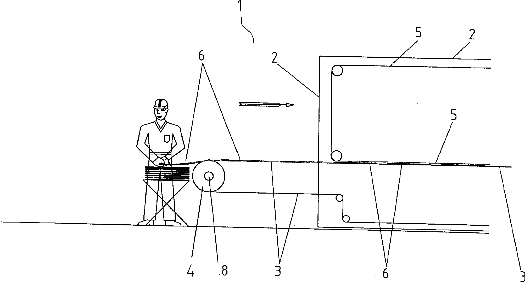
eine drehbare Saugwalze (4) gebildet ist.Dryer for veneer sheets,
with a housing (2) and a drying section formed therein,
with a lower air-permeable, endless conveyor belt (3), which is guided through the entire length of the dryer (1) and deflected at its ends,
wherein the conveyor belt (3) on an input side of the dryer (1) led out of this and the deflection is arranged outside the housing (2),
and with an air-permeable, endless shroud (5) which is guided in the drying section so that the veneer sheets (8) pressed in between the conveyor belt (3) and the shroud (5) can be transported through the drier (1),
characterized in that the input-side deflection of the conveyor belt (3) by a rotatable suction roll (4) is formed.
Description
Die Erfindung betrifft einen Trockner für Furnierblätter gemäß dem Oberbegriff des Anspruchs 1.The The invention relates to a dryer for veneer sheets according to the preamble of the claim 1.
Furnierblätter werden üblicherweise durch Messern auf z.B. Staylog- Maschinen oder auf Senkrecht- Messermaschinen hergestellt. Weiterhin ist es bekannt, Furnierblätter durch Schälen herzustellen. Hierfür wird ein radialer Längsschnitt in einen zu schälenden Baumstamm eingebracht, so dass beim Schälen kein Holzband, (das auch Endlosfurnier genannt wird,) sondern eine Vielzahl von Furnierblättern entsteht.Veneer sheets are usually by knives on e.g. Staylog machines or on vertical knives produced. Furthermore, it is known to produce veneer sheets by peeling. For this is a radial longitudinal section to be peeled in one Tree trunk introduced, so that when peeling no wooden band, (which also Endless veneer is called,) but a variety of veneer sheets is produced.
Nach
dem Schneiden beziehungsweise Schälen werden die Furnierblätter in
einem Trockner auf eine vorgegebene Restfeuchte getrocknet. Solche
Trockner sind allgemein bekannt und z.B. in der
Die
Furnierblätter
müssen
von der Messer- beziehungsweise Schälmaschine in den Trockner gegeben
werden. Hierfür
werden sie üblicherweise von
der Maschine gestapelt und anschließend von dem Stapel von Hand
auf eine Zuführvorrichtung oder
direkt auf ein Transportband des Trockners gegeben. Eine Zuführvorrichtung
ist z.B. aus der
Vollautomatische Zuführvorrichtungen haben sich wegen diverser Nachteile in der Praxis nicht durchsetzen können. Das bedeutet, dass ein Mindestmaß an Zuführarbeit immer von Hand durchgeführt werden muss.fully automatic feeders have not prevailed because of various disadvantages in practice can. This means that a minimum amount of feeding work is always done by hand got to.
Saugwalzen sind für verschiedene Einsatzzwecke z.B. in der Papierindustrie bekannt und werden hier unter anderem als Bremsvorrichtung oder als Entwässerungsvorrichtung einge setzt. Saugwalzen zur Unterstützung der Aufgabe von blattförmigem Material auf eine Transportvorrichtung sind der Anmelderin nicht bekannt.suction rolls are for various uses e.g. known in the paper industry and Here are among other things as a braking device or as a drainage device set. Suction rollers for supporting the application of sheet material to a transport device of the applicant are not known.
Aufgabe der Erfindung ist es, einen Trockner zu schaffen, bei dem die manuelle Zuführung von blattförmigen Furnieren auf ein Transporband erleichtert ist.task The invention is to provide a dryer in which the manual feed of leaf-shaped Veneering on a conveyor belt is facilitated.
Die Aufgabe ist durch die Merkmale des Anspruchs 1 gelöst. Die Ausbildung der eingangsseitigen Umlenkung als Saugwalze bewirkt, dass ein Furnierblatt, das in die Nähe der Saugwalze gelangt, von dem Unterdruck angezogen und auf dem Transportband festgehalten wird. Hierdurch wird das Furnierblatt von dem Transportband schnell und sicher in den Trockner gefördert. Das Betriebspersonal ist stark entlastet, weil nur noch ein Teil des Furnierblatts in die Nähe der Saugwalze gebracht werden muss und dann das Furnierblatt Iosgelassen werden kann – und nicht mehr wie bisher weitgehend als Ganzes auf das Transportband gelegt werden muss. Hierdurch ist einerseits der Bewegungsablauf für das Betriebspersonal vereinfacht und andererseits ein schnelleres Aufgeben des folgenden Furnierblatts möglich, so dass eine dichtere Belegung des Transportbands und somit eine höhere Kapazität des Trockners sowie ein besserer Wirkungsgrad erzielt werden können.The The object is solved by the features of claim 1. The Forming the input-side deflection causes a suction roller, that a veneer sheet, which comes in the vicinity of the suction roll, of the Vacuum is tightened and held on the conveyor belt. As a result, the veneer sheet of the conveyor belt is fast and safely transported to the dryer. The operating staff is greatly relieved, because only a part of the veneer in the vicinity the suction roll must be brought and then released the veneer sheet can be - and no longer as before largely as a whole on the conveyor belt must be laid. As a result, on the one hand the movement for the Facilitates operating personnel and on the other hand, a faster abandonment the following veneer possible, so that a denser occupancy of the conveyor belt and thus a higher capacity the dryer and a better efficiency can be achieved.
Die Unteransprüche betreffen die vorteilhafte Ausgestaltung der Erfindung.The under claims relate to the advantageous embodiment of the invention.
Die Begrenzung des wirksamen Umfangs der Saugwalze nach den Ansprüchen 2 und 3 bewirkt eine erhebliche Einsparung an Saugluft, ohne dass die Wirksamkeit vermindert wird.The Limiting the effective size of the suction roll according to claims 2 and 3 causes a significant saving in suction without the Effectiveness is reduced.
Die Verminderte Lochzahl pro Flächeneinheit in den Randbereichen nach Anspruch 4 bewirkt eine weitere Verminderung der erforderlichen Menge an Saugluft, wobei eine verminderte Saugkraft in den Randbereichen, die seltener von Furnierblättern bedeckt sind, nicht behindernd wirkt. Es hat sich gezeigt, dass auch große Furnierblätter sicher vom Unterdruck erfasst und problemlos in den Trockner gefördert werden.The Reduced number of holes per unit area in the edge regions according to claim 4 causes a further reduction the required amount of suction, with a reduced suction power not obstructing in the marginal areas, which are less often covered by veneer sheets acts. It has been proven that even large veneer sheets are safe be detected by the negative pressure and conveyed easily into the dryer.
Die Saugwalze mit drehbarer Befestigung des Mantels auf der Saugleitung ist einfach zu montieren und eignet sich daher besonders für die Nachrüstung an bestehenden Trocknern.The Suction roll with rotatable attachment of the jacket on the suction line is easy to install and is therefore particularly suitable for retrofitting existing dryers.
Die Erfindung wird anhand eines vereinfacht dargestellten Ausführungsbeispiels weiter erläutert. Es zeigenThe invention is simplified by means of a illustrated embodiment further explained. Show it
Wie
aus den
Der
Trockner
Wie
aus den
In
der Saugwalze
In
die Saugleitung
Im
Betrieb steht Betriebspersonal in der Nähe der Saugwalze
Alternativ
beträgt
der Winkel α zwischen
den Blechen
Claims (7)
Priority Applications (2)
| Application Number | Priority Date | Filing Date | Title |
|---|---|---|---|
| DE200410040552 DE102004040552B4 (en) | 2004-08-21 | 2004-08-21 | Dryers for veneer sheets |
| PCT/EP2005/008418 WO2006021305A1 (en) | 2004-08-21 | 2005-08-03 | Drier for veneer sheets |
Applications Claiming Priority (1)
| Application Number | Priority Date | Filing Date | Title |
|---|---|---|---|
| DE200410040552 DE102004040552B4 (en) | 2004-08-21 | 2004-08-21 | Dryers for veneer sheets |
Publications (2)
| Publication Number | Publication Date |
|---|---|
| DE102004040552A1 DE102004040552A1 (en) | 2006-03-09 |
| DE102004040552B4 true DE102004040552B4 (en) | 2007-02-08 |
Family
ID=35347048
Family Applications (1)
| Application Number | Title | Priority Date | Filing Date |
|---|---|---|---|
| DE200410040552 Expired - Fee Related DE102004040552B4 (en) | 2004-08-21 | 2004-08-21 | Dryers for veneer sheets |
Country Status (2)
| Country | Link |
|---|---|
| DE (1) | DE102004040552B4 (en) |
| WO (1) | WO2006021305A1 (en) |
Families Citing this family (1)
| Publication number | Priority date | Publication date | Assignee | Title |
|---|---|---|---|---|
| RU2009123284A (en) * | 2009-06-19 | 2010-12-27 | Андрей Виленович Любомирский (RU) | TAPE MOVEMENT ROLLER |
Citations (2)
| Publication number | Priority date | Publication date | Assignee | Title |
|---|---|---|---|---|
| DE2523482A1 (en) * | 1974-11-06 | 1976-05-20 | Angelo Cremona | DEVICE FOR INDEPENDENT LOADING MOISTURIZED VENEER SHEETS INTO A BELT OR DRUM DRYER AND FOR UNLOADING AND STACKING THE ESCAPED DRIED VENEER SHEETS |
| US4654981A (en) * | 1984-02-17 | 1987-04-07 | Babcock-Bsh Aktiengesellschaft | Drying apparatus for sliced veneer |
Family Cites Families (11)
| Publication number | Priority date | Publication date | Assignee | Title |
|---|---|---|---|---|
| GB857760A (en) * | 1956-11-23 | 1961-01-04 | Johann Fleissner | Improvements in and relating to sieve drum driers |
| DE1278950B (en) * | 1959-04-14 | 1968-09-26 | Fleissner G M B H | Cover plate arrangement on a device for drying or wet treatment of treatment agent-permeable or impermeable material |
| GB907931A (en) * | 1959-03-26 | 1962-10-10 | Fleissner Gmbh | Improvements in and relating to drum sieve driers |
| ES355360A1 (en) * | 1968-04-23 | 1969-11-16 | Cremona Angelo | A continuous wood shearing and drying process and equipment to carry out such process |
| US3818607A (en) * | 1969-02-14 | 1974-06-25 | Vepa Ag | Process and apparatus for the treatment of material lengths |
| DE8313760U1 (en) * | 1983-05-09 | 1983-12-22 | Brückner Trockentechnik GmbH & Co KG, 7250 Leonberg | HOT AIR TREATMENT DEVICE FOR CONTINUOUSLY TRANSPORTED TEXTILE GOODS |
| DK107985A (en) * | 1985-03-08 | 1986-09-09 | Moeller & Jochumsen As | PROCEDURE AND PLANT FOR THE PREPARATION OF A TARGET, SHAPE-SHAPED MATERIALS INCLUDING ORGANIC FIBERS, WHICH THE MAIN PARTY IS CELLULOSE FIBER, AND A BINDING AGENT |
| RU1768486C (en) * | 1989-02-03 | 1992-10-15 | Украинская сельскохозяйственная академия | Device for feeding veneer sheets into operating zone |
| DE19512848C1 (en) * | 1995-04-06 | 1996-05-09 | Babcock Bsh Ag | Dryer and/or cooler for moving veneer panels |
| DE19525544C1 (en) * | 1995-07-13 | 1996-10-02 | Babcock Bsh Ag | Dryer and/or cooler for continuously passing veneer sheets |
| DE19910832C1 (en) * | 1999-03-11 | 2000-04-27 | Babcock Bsh Gmbh | Method for drying wood veneer sheets has the sheets aligned with the grain at an angle to the transport direction through the dryers |
-
2004
- 2004-08-21 DE DE200410040552 patent/DE102004040552B4/en not_active Expired - Fee Related
-
2005
- 2005-08-03 WO PCT/EP2005/008418 patent/WO2006021305A1/en not_active Ceased
Patent Citations (2)
| Publication number | Priority date | Publication date | Assignee | Title |
|---|---|---|---|---|
| DE2523482A1 (en) * | 1974-11-06 | 1976-05-20 | Angelo Cremona | DEVICE FOR INDEPENDENT LOADING MOISTURIZED VENEER SHEETS INTO A BELT OR DRUM DRYER AND FOR UNLOADING AND STACKING THE ESCAPED DRIED VENEER SHEETS |
| US4654981A (en) * | 1984-02-17 | 1987-04-07 | Babcock-Bsh Aktiengesellschaft | Drying apparatus for sliced veneer |
Also Published As
| Publication number | Publication date |
|---|---|
| DE102004040552A1 (en) | 2006-03-09 |
| WO2006021305A1 (en) | 2006-03-02 |
Similar Documents
| Publication | Publication Date | Title |
|---|---|---|
| DE1303136B (en) | ||
| DE1292990B (en) | Device for the simultaneous carrying, transporting and guiding of a material web by means of a supplied gaseous flow means | |
| DE1435069C3 (en) | Removal device for separating permeable pieces of tissue from a stack | |
| DE2323519A1 (en) | WEDGE PRESS FOR CONTINUOUS DEWATERING OF A FIBER WEB, IN PARTICULAR FIBER PANEL | |
| EP1914344A1 (en) | Compressed bale shredder | |
| DE3539233A1 (en) | METHOD AND DEVICE FOR TREATING A SLURRY | |
| DE2504295A1 (en) | DEVICE FOR THE MANUFACTURING OF DISPOSABLE DIAPERS | |
| DE3838078A1 (en) | Apparatus for conveying an especially imbricated stream of sheets | |
| DE2714161C3 (en) | Device for transferring the beginning of a paper web | |
| DE2550956A1 (en) | BELT FILTER PRESS | |
| DE2628338A1 (en) | DEVICE FOR PULLING OFF ONE LETTER OR DGL. FROM A PILE | |
| DE2636887A1 (en) | DEVICE FOR THE TRANSFER OF A GUIDE STRIP FOR A PAPER MACHINE O.AE. | |
| DE102004040552B4 (en) | Dryers for veneer sheets | |
| DE2757257C3 (en) | Wilting press for leather, furs and the like. | |
| EP0079607A1 (en) | Continuous press, in particular a samming machine for manufacturing and processing leather | |
| DE2365438A1 (en) | Paper web drying section support belt - particularly for use in feeding in paper strip | |
| DE4101856C1 (en) | Dewatering device partic for sludge of paper fibres | |
| DE3020839C2 (en) | Device for feeding items of laundry or the like to a mangle or the like. | |
| CH643515A5 (en) | STACKING DEVICE FOR FLAT PROPERTIES, LIKE BANKNOTES, RECEIPTS AND THE LIKE. | |
| DE2644375C3 (en) | Device for continuously wrapping a plastic drainage pipe with a filter jacket | |
| DE3020119A1 (en) | Washing machine for fibrous material, e.g. paper pulp - provides vacuum filtration, and eliminates re-grinding | |
| DE2305547B2 (en) | Device for continuous dewatering of sewage sludge, pulp waste sludge or the like | |
| CH382721A (en) | Method and device for treating fiber material, in particular asbestos fibers | |
| DE2559553C2 (en) | Device for the production of fiber boards, in particular asbestos-cement boards | |
| AT140080B (en) | Method and device for the continuous processing of waste paper, waste paper, wood pulp, cellulose and the like. like |
Legal Events
| Date | Code | Title | Description |
|---|---|---|---|
| OP8 | Request for examination as to paragraph 44 patent law | ||
| 8364 | No opposition during term of opposition | ||
| 8339 | Ceased/non-payment of the annual fee |