CN219004900U - Sensor oil filling port automatic sealing equipment compatible with steel balls and pins - Google Patents
Sensor oil filling port automatic sealing equipment compatible with steel balls and pins Download PDFInfo
- Publication number
- CN219004900U CN219004900U CN202223476988.8U CN202223476988U CN219004900U CN 219004900 U CN219004900 U CN 219004900U CN 202223476988 U CN202223476988 U CN 202223476988U CN 219004900 U CN219004900 U CN 219004900U
- Authority
- CN
- China
- Prior art keywords
- pin
- sensor
- cylinder
- steel ball
- tray
- Prior art date
- Legal status (The legal status is an assumption and is not a legal conclusion. Google has not performed a legal analysis and makes no representation as to the accuracy of the status listed.)
- Active
Links
Images


Abstract
The utility model discloses sensor oil filling port automatic sealing equipment compatible with steel balls and pins, wherein a tray loading and unloading mechanism is used for disassembling a single tray, transmitting the single tray to a preset working position and stacking empty trays; the workpiece feeding mechanism conveys the sensor to a station of the visual alignment pin shifting mechanism; the visual alignment pin shifting mechanism can rotate the sensor to a preset angle by utilizing a visual alignment technology, and shift pins to an avoidance position; the steel ball/pin feeding mechanism feeds the steel ball/pin to the oil filling port; the transfer mechanism transfers the sensor to the welding pin gathering mechanism for sealing welding between the steel ball/pin and the oil filling port, and folds the pins; the unloading mechanism of pouring oil can collect residual oil to shift out the sensor transportation. By the technical scheme, the whole process automatic operation is realized, manual intervention is not needed, the degree of automation is high, the welding quality is stable, and the production cost is remarkably reduced.
Description
Technical Field
The utility model relates to the technical field of resistance welding, in particular to automatic sealing equipment for a sensor oil filling port compatible with steel balls and pins.
Background
The pressure sensor is characterized in that the measured pressure is transmitted to the silicon piezoresistive sensitive element through the isolating diaphragm and the filled silicon oil, so that the accurate conversion from the pressure to the electric signal is realized. In the production and manufacturing process of the sensor, an oil filling port of the sensor filled with silicone oil is required to be sealed by adopting a resistance welding mode through steel balls or pins, the steel balls or pins are required to be placed above the oil filling port of the sensor before welding, the sensor is placed below a resistance welding machine, and the steel balls and the pins on the oil filling port are required to be coaxial with an electrode rod on the welding machine.
In the existing manual steel ball or pin placing process, the sensor, the steel ball and the pin are small in size, so that manual operation is inconvenient, and feeding welding cannot be performed fully automatically. Before each welding, whether the oil filling port is coaxial with the upper electrode or not needs to be visually checked, and an operator needs to keep a certain safety distance from the welding machine, so that the sensor manufacturing process takes longer and has lower production efficiency.
Disclosure of Invention
According to the sensor oil filling port automatic sealing device compatible with steel balls and pins, the tray with stacked layers is split and fed to a working position through the tray feeding and discharging mechanism, the empty tray with the workpieces being taken is stacked to a specific position again, the unwelded sensors in the tray feeding and discharging working position are sequentially fed to the visual alignment pin shifting mechanism through the workpiece feeding mechanism, the sensor oil filling port is rotated to a specific position through the visual alignment technology, the pins of the sensor are shifted to an avoidance position to avoid a specific area range above the oil filling port, the steel balls/pins are automatically fed to the sensor oil filling port through the steel balls/pins feeding mechanism, the sensors with the beads/pins being placed are fed to the welding pin gathering mechanism through the transfer mechanism to finish sealing welding and pin folding, residual oil in the welded sensors is collected into the oil receiving groove through the discharging oil pouring mechanism and is discharged to downstream equipment, automatic tray disassembly, automatic loading, automatic alignment, automatic welding, automatic pin pouring and automatic oil pouring are achieved, manual intervention is not needed, the production cost is lowered, and the production stability is high, and the production cost is remarkably reduced.
The utility model provides sensor oil filling port automatic sealing equipment compatible with steel balls and pins, which comprises a workbench, and a tray feeding and discharging mechanism, a workpiece feeding mechanism, a visual alignment pin shifting mechanism, a steel ball/pin feeding mechanism, a transfer mechanism, a welding pin gathering mechanism and a discharging oil pouring mechanism which are arranged on the workbench;
the tray loading and unloading mechanism is used for separating a single tray from the trays with multiple stacked layers, conveying the single tray to a preset working position, and conveying an empty tray with the completed work to the preset position for stacking;
the workpiece feeding mechanism can convey the sensor to a station of the visual alignment pin shifting mechanism from a single tray at a preset working position;
the visual alignment pin shifting mechanism can rotate an oil filling port of the sensor to a preset angle by utilizing a visual alignment technology, and shift pins of the sensor to an avoidance position;
the steel ball/pin feeding mechanism can feed the steel ball/pin from the avoidance position to an oil filling port of the sensor;
the transfer mechanism can transfer the sensor after the steel balls/pins are placed to the welding pin gathering mechanism;
the welding pin gathering mechanism can realize sealing welding between the steel ball/pin and the oil filling port, and fold pins of the sensor to the original position;
the unloading oil pouring mechanism can collect the residual oil on the sensor that the welding is accomplished, and will the sensor is transported out.
In the above technical solution, preferably, the tray loading and unloading mechanism includes a stacked tray splitting assembly, a tray moving module and a tray stacking assembly;
the tray split assembly can split the single tray at the uppermost layer of the stacked multi-layer trays, the tray moving module moves the split single tray to a preset working position, and after the sensor placed on the single tray is taken away, the tray moving module can move the empty tray to the tray stack assembly for stacking.
In the above technical scheme, preferably, the workpiece feeding mechanism comprises a Y-direction support, a Y-direction moving module, a first lifting cylinder, a first clamping jaw and a clamping finger;
the Y-direction support is arranged on the workbench, the Y-direction moving module is arranged on the side wall of the Y-direction support, the first lifting cylinder is arranged at the movable end of the Y-direction moving module, the first clamping jaw is arranged at the movable end of the first lifting cylinder, and the clamping finger is arranged at the movable end of the first clamping jaw;
the first clamping jaw can drive the clamping finger to clamp the sensor on the tray at a preset working position, and can transfer the sensor from the tray to a station of the visual alignment pin shifting mechanism under the driving action of the Y-direction moving module and the first lifting cylinder.
In the above technical solution, preferably, the visual alignment pin-pulling mechanism includes a supporting seat, a guide rail slider, a lifting slider connecting seat, a screw assembly, a lifting motor, a rotating shaft assembly, a second clamping jaw, an alignment rotating motor, a pin-pulling primary sliding table cylinder, a pin-pulling secondary sliding table cylinder, a pin-dividing air claw, a pin-dividing pin-pulling needle, a camera, a light source and a visual bracket;
the support seat is arranged on the workbench, the guide rail sliding block is vertically arranged on the side surface of the support seat, the lifting sliding block connecting seat is vertically arranged at the movable end of the guide rail sliding block and is connected with the movable end of the lead screw assembly, the lead screw assembly is vertically fixed on the support seat, the lifting motor is arranged on the support seat and is connected with the lead screw assembly, the rotating shaft system assembly is arranged on the lifting sliding block connecting seat, the second clamping jaw is arranged on the rotating shaft system assembly, the alignment rotating motor is arranged on the lifting sliding block connecting seat and is connected with the rotating shaft system assembly, the pin shifting first-stage sliding table cylinder is arranged at the rear end of the support seat, the pin shifting second-stage sliding table cylinder is arranged at the movable end of the pin shifting first-stage sliding table cylinder, the pin shifting claw is arranged at the movable end of the pin shifting second-stage sliding table cylinder, the pin shifting needle is arranged at the front end of the pin shifting claw, the camera is arranged on the side surface of the visual support, the light source is arranged below the light source and is connected with the visual support seat;
the second clamping jaw can clamp the sensor and can move along the guide rail sliding block and the screw rod assembly under the driving action of the lifting motor;
under the illumination support of the light source, the camera can acquire the image of the sensor in real time, and the position and the angle of the oil filling port on the sensor can be obtained according to real-time image analysis based on a visual alignment technology;
the rotary shaft system assembly can drive the sensor to rotate until the oil filling port reaches a preset angle under the drive of the alignment rotary motor;
under the drive of dial pin one-level slip table cylinder with dial pin second grade slip table cylinder, divide the pin gas claw can drive divide the pin and dial the needle and remove, so as to with the pin of sensor is separately to dodge the position, make steel ball/pin can move smoothly to the oiling mouth position of sensor.
In the above technical solution, preferably, the steel ball/pin feeding mechanism includes a steel ball/pin distributor and a feeding manipulator;
the steel ball/pin distributing machine comprises a steel ball/pin distributing bin, a correlation sensor, a guide shaft, a linear bearing, a steel ball/pin distributing rod, a floating joint and a jacking air cylinder, wherein a bin cover plate is arranged on the steel ball/pin distributing bin, the steel ball/pin distributing bin is arranged on a bin connecting plate, the correlation sensor is arranged on a sensor bracket, the sensor bracket is arranged on the bin connecting plate, the bin connecting plate is arranged on a vertical plate and connected with the guide shaft, the vertical plate is arranged on a bottom plate, the bottom plate is arranged on a workbench, the linear bearing is sleeved on the guide shaft, the steel ball/pin distributing rod is connected with the linear bearing through a linear bearing connecting plate, the floating joint is arranged below the linear bearing connecting plate, and the jacking air cylinder is fixed on an air cylinder connecting plate at the lower end of the guide shaft;
under the jacking action of the jacking cylinder and the guiding action of the guide shaft, the steel ball/pin distributing rod moves upwards to eject steel balls/pins in the steel ball/pin distributing bin from holes reserved at corresponding positions of the bin cover plate, and whether steel balls/pins are ejected or not is detected by the correlation sensor;
the feeding manipulator comprises an X-direction support, an X-direction moving module, a lifting sliding table cylinder, a manual displacement platform, an upper connecting plate, a guide assembly, a spring, a lower connecting plate, a vacuum suction nozzle seat and a suction nozzle, wherein the X-direction support is arranged on the workbench, the X-direction moving module is arranged on the side wall of the X-direction support, the lifting sliding table cylinder is arranged at the movable end of the X-direction moving module, the manual displacement platform is arranged at the movable end of the lifting sliding table cylinder, the upper connecting plate is arranged at the movable end of the manual displacement platform, the guide assembly is arranged below the upper connecting plate, the spring is arranged at the periphery of the guide assembly, the lower connecting plate is arranged below the guide assembly, the vacuum suction nozzle seat is arranged below the lower connecting plate, and the suction nozzle is arranged below the vacuum suction nozzle seat.
The suction nozzle moves to the upper part of the steel ball/pin distributing bin and adsorbs the steel ball/pin under the driving action of the lifting sliding table cylinder and the manual displacement platform and the guiding action of the guiding component, and then the steel ball/pin is transferred to the oil filling port of the sensor.
In the above technical solution, preferably, the transfer mechanism includes a transfer moving module, a cantilever connecting seat, a lifting cylinder, a transfer clamping jaw and a transfer clamping finger, where the transfer moving module is disposed on the workbench, the cantilever connecting seat is disposed at a moving end of the transfer moving module, the lifting cylinder is disposed at a side surface of the cantilever connecting seat, the transfer clamping jaw is disposed at a movable end of the lifting cylinder, and the transfer clamping finger is disposed at a movable end of the transfer clamping jaw;
the transfer clamping jaw can drive the transfer clamping finger to clamp the sensor with the steel balls/pins, and transfer the sensor to a welding station of the welding pin gathering mechanism under the driving action of the transfer moving module and the lifting cylinder.
In the above technical solution, preferably, the welding pin gathering mechanism includes a resistance welding machine head, a cylinder support, a folding cylinder and pin gathering clamping pieces, the resistance welding machine head is arranged on the workbench, the cylinder support is arranged on two sides of the resistance welding machine head, the folding cylinder is arranged above the cylinder support, and the pin gathering clamping pieces are arranged on the movable sides of the folding cylinder;
the resistance welding machine head is used for sealing and welding the steel ball/pin and the oil filling port of the sensor, and the pin gathering clamping piece can fold pins which are in avoidance position on the sensor to the original position under the driving of the folding cylinder.
In the above technical solution, preferably, the discharging oil pouring mechanism includes a discharging X-axis moving module, a Z-axis moving module, a cantilever frame, a horizontal pushing cylinder, a vertical seat, a speed reducer, a discharging rotating motor, a discharging clamping jaw, a discharging clamping finger and an oil receiving groove component, the discharging X-axis moving module is arranged on the workbench, the Z-axis moving module is vertically arranged at the movable end of the discharging X-axis moving module through a connecting seat, the cantilever frame is arranged at the movable end of the Z-axis moving module, the horizontal pushing cylinder is arranged on the cantilever frame, the vertical seat is arranged at the movable end of the horizontal pushing cylinder, the speed reducer is arranged at the rear of the vertical seat, the discharging rotating motor is arranged at the input end of the speed reducer, the discharging clamping jaw is arranged at the output end of the speed reducer, the discharging clamping finger is arranged at the movable end of the discharging clamping jaw, and the oil receiving groove component is arranged on the workbench;
the blanking clamping jaw can move to a station of the welding pin gathering mechanism under the driving action of the blanking X-axis moving module and the Z-axis moving module, and clamps the welded sensor to the upper part of the oil receiving groove component, the sensor can be driven to be reversed under the driving action of the blanking rotating motor so as to pour residual oil into the oil receiving groove component, and the sensor can be transported out of the current station under the driving action of the flat pushing cylinder.
Compared with the prior art, the utility model has the beneficial effects that: the tray loading and unloading mechanism is used for splitting and loading the trays with multiple layers stacked to the working position, the empty trays with the workpieces completely taken are stacked to the specific positions again, the unwelded sensors in the tray loading and unloading working position are sequentially loaded to the visual alignment pin shifting mechanism through the workpiece loading mechanism, the sensor oil filling port is rotated to the specific positions through the visual alignment technology, the sensor pins are shifted to the avoidance position so as to avoid the specific area range above the oil filling port, the steel balls/pins are automatically loaded to the sensor oil filling port through the steel ball/pin loading mechanism, the sensors with the beads/pins are loaded to the welding pin gathering mechanism through the transfer mechanism so as to complete sealing welding and pin folding, and residual oil in the welded sensors is collected into the oil receiving tank through the unloading oil pouring mechanism and is discharged to downstream equipment, so that automatic disc disassembly, automatic code disc, automatic loading, automatic alignment, automatic bead/pin welding and automatic oil pouring operation are realized, the automatic intervention is not needed, the automation degree is high, the welding quality is remarkably reduced.
Drawings
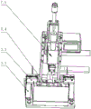
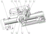
Fig. 1 is a schematic diagram of the overall structure of an automatic sealing device for an oil filling port of a sensor compatible with steel balls and pins according to an embodiment of the present utility model;
fig. 2 is a schematic structural diagram of a tray feeding and discharging mechanism according to an embodiment of the present utility model;
FIG. 3 is a schematic structural view of a workpiece loading mechanism according to an embodiment of the present utility model;
FIG. 4 is a schematic diagram of a visual alignment pin shifting mechanism according to an embodiment of the present utility model;
fig. 5 is a schematic structural view of a steel ball/pin feeding mechanism according to an embodiment of the present utility model;
fig. 6 is a schematic structural view of a steel ball/pin dispenser according to an embodiment of the present utility model;
fig. 7 is a schematic structural diagram of a feeding manipulator according to an embodiment of the present utility model;
FIG. 8 is a schematic diagram of a transfer mechanism according to an embodiment of the present utility model;
FIG. 9 is a schematic diagram of a soldering pin gathering mechanism according to an embodiment of the present utility model;
fig. 10 is a schematic structural diagram of a blanking and oil pouring mechanism according to an embodiment of the present utility model.
In the figure, the correspondence between each component and the reference numeral is:
1. a work table;
2. a tray loading and unloading mechanism; 2.1, a tray moving module; 2.2, stacking the tray split assembly; 2.3, a tray stacking assembly;
3. a workpiece feeding mechanism; 3.1, Y-direction supports; 3.2, Y moves the die set; 3.3, a first lifting cylinder; 3.4, a first clamping jaw; 3.5, clamping fingers;
4. a visual alignment pin shifting mechanism; 4.1, a supporting seat; 4.2, a guide rail sliding block; 4.3, lifting the sliding block connecting seat; 4.4, a screw rod assembly; 4.5, lifting the motor; 4.6, a rotating shaft system assembly; 4.7, a second clamping jaw; 4.8, aligning the rotating motor; 4.9, a pin shifting primary sliding table cylinder; 4.10, a pin shifting secondary slipway cylinder; 4.11, pin dividing air claws; 4.12, pin dividing poking needles; 4.13, camera; 4.14, a light source; 4.15, a visual support;
5. steel ball/pin feeding mechanism; 5.1, a steel ball/pin distributor; 5.1.1, a bin cover plate; 5.1.2, steel ball/pin distributing bin; 5.1.3, a bin connecting plate; 5.1.4, sensor holder; 5.1.5, correlation sensor; 5.1.6, vertical plates; 5.1.7, bottom plate; 5.1.8, guiding shaft; 5.1.9, linear bearings; 5.1.10, linear bearing connection plates; 5.1.11, steel ball/pin feed rod; 5.1.12, floating joint; 5.1.13, cylinder connecting plate; 5.1.14, jacking cylinder; 5.2, a pin distributor; 5.3, a feeding manipulator; 5.3.1, X-direction support; 5.3.2, X direction moving module; 5.3.3, lifting the slipway cylinder; 5.3.4, manual displacement platform; 5.3.5, upper connecting plate; 5.3.6, a guide assembly; 5.3.7, springs; 5.3.8, lower connecting plate; 5.3.9, vacuum nozzle mount; 5.3.10, suction nozzle;
6. a transfer mechanism; 6.1, transferring the mobile module; 6.2, cantilever connecting seat; 6.3, lifting cylinder; 6.4, transferring clamping jaws; 6.5, transferring the clamping finger;
7. welding a pin gathering mechanism; 7.1, a resistance welding head; 7.2, a cylinder support; 7.5, closing the air cylinder; 7.4, gathering pin clamping pieces;
8. a blanking and oil pouring mechanism; 8.1, blanking an X-axis moving module; 8.2, connecting seat; 8.3, a Z-axis moving module; 8.4, cantilever mount; 8.5, a horizontal pushing cylinder; 8.6, standing; 8.7, a speed reducer; 8.8, blanking a rotating motor; 8.9, blanking clamping jaws; 8.10, blanking clamping fingers; 8.11, oil receiving groove component.
Detailed Description
For the purpose of making the objects, technical solutions and advantages of the embodiments of the present utility model more apparent, the technical solutions of the embodiments of the present utility model will be clearly and completely described below with reference to the accompanying drawings in the embodiments of the present utility model, and it is apparent that the described embodiments are some embodiments of the present utility model, but not all embodiments of the present utility model. All other embodiments, which can be made by those skilled in the art based on the embodiments of the utility model without making any inventive effort, are intended to be within the scope of the utility model.
The utility model is described in further detail below with reference to the attached drawing figures:
as shown in fig. 1, the automatic sealing device for the sensor oil filling port compatible with steel balls and pins provided by the utility model comprises a workbench 1, a tray feeding and discharging mechanism 2, a workpiece feeding mechanism 3, a visual alignment pin shifting mechanism 4, a steel ball/pin feeding mechanism 5, a transfer mechanism 6, a welding pin gathering mechanism 7 and a discharging and oil pouring mechanism 8, wherein the tray feeding and discharging mechanism 2, the workpiece feeding mechanism 3, the visual alignment pin shifting mechanism 4, the steel ball/pin feeding mechanism 5, the transfer mechanism 6 and the welding pin gathering mechanism 7 are arranged on the workbench 1.
The tray loading and unloading mechanism 2 is used for separating a single tray from the trays with multiple stacked layers, conveying the single tray to a preset working position, and conveying an empty tray with the completed work to the preset position for stacking.
The workpiece feeding mechanism 3 can convey the sensor to a station of the visual alignment pin shifting mechanism 4 from a single tray at a preset working position.
The visual alignment pin shifting mechanism 4 can rotate an oil filling port of the sensor to a preset angle by utilizing a visual alignment technology, and shift pins of the sensor to an avoidance position.
The steel ball/pin feeding mechanism 5 can feed the steel ball/pin from the avoidance position to the oil filling port of the sensor.
The transfer mechanism 6 can transfer the sensor after placing the steel ball/pin to the welding pin gathering mechanism 7.
The welding pin gathering mechanism 7 can realize sealing welding between the steel ball/pin and the oil filling port, and fold pins of the sensor to the original position.
The unloading mechanism 8 of pouring oil can collect the residual oil on the sensor that the welding accomplished to shift out the sensor.
In this embodiment, the trays stacked in multiple layers are split and fed to the working position through the tray feeding and discharging mechanism 2, the empty trays after the workpieces are taken are stacked to the specific position again, the unwelded sensors in the tray feeding and discharging working position are sequentially fed to the visual alignment pin shifting mechanism 4 through the workpiece feeding mechanism 3, the sensor oil filling port is rotated to the specific position through the visual alignment technology, the sensor pins are shifted to the avoidance position to avoid the specific area range above the oil filling port, the steel balls/pins are automatically fed to the sensor oil filling port through the steel ball/pin feeding mechanism, the sensors after the beads/pins are fed to the welding pin gathering mechanism 7 through the transfer mechanism 6 to complete sealing welding and pin folding, residual oil in the sensors after the welding is collected into the oil receiving groove through the unloading oil pouring mechanism 8 and is fed to downstream equipment, automatic disc disassembly, automatic code disc, automatic feeding, automatic alignment, automatic bead/pin welding and automatic oil pouring operation are not needed, manual intervention is performed, the automatic quality is high, the stable production cost is remarkably reduced.
As shown in fig. 2, in the above embodiment, the tray loading and unloading mechanism 2 preferably includes a stacked tray splitting assembly 2.2, a tray moving module 2.1, and a tray stacking assembly 2.3.
In the implementation process, the trays of stacking multiple layers are manually placed on the stacking tray splitting assembly 2.2, the stacking tray splitting assembly 2.2 can split the single tray at the uppermost layer of the trays of the stacking multiple layers, the tray moving module 2.1 moves the split single tray to a preset working position, and after the sensors placed on the single tray are taken away, the tray moving module 2.1 can move the empty tray to the tray stacking assembly 2.3 for stacking. After the empty trays are stacked to a certain amount or height, the equipment can send out prompt information to prompt the staff to withdraw the empty trays.
As shown in fig. 3, in the above embodiment, the workpiece feeding mechanism 3 preferably includes a Y-direction support 3.1, a Y-direction moving module 3.2, a first lifting cylinder 3.3, a first clamping jaw 3.4, and a clamping finger 3.5.
The Y is to support 3.1 setting on workstation 1, and Y is to removing module 3.2 setting on the lateral wall of Y to support 3.1, and first lift cylinder 3.3 sets up in Y to removing the expansion end of module 3.2, and first clamping jaw 3.4 sets up in the expansion end of first lift cylinder 3.3, presss from both sides the expansion end that indicates 3.5 setting in first clamping jaw 3.4.
The first clamping jaw 3.4 can drive the clamping finger 3.5 to clamp the sensor on the tray of the preset working position, and can transfer the sensor from the tray to the station of the visual alignment pin shifting mechanism 4 under the driving action of the Y-direction moving module 3.2 and the first lifting cylinder 3.3. Specifically, the Y-direction moving module 3.2 moves to the top of the tray at the working position, the first lifting cylinder 3.3 descends, the first clamping jaw 3.4 is closed to grab the sensor supported on the tray, the first lifting cylinder 3.3 ascends, and the Y-direction moving module 3.2 moves to the vision alignment pin shifting mechanism 4 to carry out discharging.
As shown in fig. 4, in the above embodiment, preferably, the visual alignment pin shifting mechanism 4 includes a supporting seat 4.1, a guide rail sliding block 4.2, a lifting sliding block connecting seat 4.3, a screw rod assembly 4.4, a lifting motor 4.5, a rotating shaft assembly 4.6, a second clamping jaw 4.7, an alignment rotating motor 4.8, a pin shifting primary sliding table cylinder 4.9, a pin shifting secondary sliding table cylinder 4.10, a pin shifting claw 4.11, a pin shifting pin 4.12, a camera 4.13, a light source 4.14 and a visual bracket 4.15.
The supporting seat 4.1 is arranged on the workbench 1, the guide rail sliding block 4.2 is vertically arranged on the side surface of the supporting seat 4.1, the lifting sliding block connecting seat 4.3 is vertically arranged at the movable end of the guide rail sliding block 4.2 and is connected with the movable end of the lead screw assembly 4.4, the lead screw assembly 4.4 is vertically fixed on the supporting seat 4.1, the lifting motor 4.5 is arranged on the supporting seat 4.1 and is connected with the lead screw assembly 4.4, the rotating shaft system assembly 4.6 is arranged on the lifting sliding block connecting seat 4.3, the second clamping jaw 4.7 is arranged on the rotating shaft system assembly 4.6, the alignment rotating motor 4.8 is arranged on the lifting sliding block connecting seat 4.3 and is connected with the rotating shaft system assembly 4.6, the pin shifting primary sliding table cylinder 4.9 is arranged at the rear end of the supporting seat 4.1, the pin shifting secondary sliding table cylinder 4.10 is arranged at the movable end of the pin shifting primary sliding table cylinder 4.9, the pin shifting pin 4.12 is arranged at the movable end of the pin shifting secondary sliding table cylinder 4.10, the pin shifting pin 4.11 is arranged at the front end of the pin shifting pin 4.11 and is arranged at the camera 4.13.15.15, and the visual support is arranged at the side surface of the camera 4.4.15.4.15 and is connected with the visual support frame 4.1.
The second clamping jaw 4.7 can clamp the sensor and can move along the guide rail sliding block 4.2 and the screw rod assembly 4.4 under the driving action of the lifting motor 4.5.
Under the illumination support of the light source 4.14, the camera 4.13 can acquire the image of the sensor in real time, and the position and the angle of the oil filling port on the sensor can be obtained according to real-time image analysis based on the visual alignment technology.
The rotary shaft system assembly 4.6 can drive the sensor to rotate until the oil filling port reaches a preset angle under the driving of the contraposition rotary motor 4.8.
Under the drive of a pin shifting primary sliding table cylinder 4.9 and a pin shifting secondary sliding table cylinder 4.10, the pin shifting claw 4.11 can drive the pin shifting pin 4.12 to move so as to separate pins of the sensor to an avoidance position, and the steel ball/pin can smoothly move to the oil filling port of the sensor.
As shown in fig. 5, in the above embodiment, preferably, the steel ball/pin feeding mechanism 5 includes a steel ball/pin dispenser 5.1 and a feeding robot 5.3.
As shown in fig. 6, the steel ball/pin distributor 5.1 includes a steel ball/pin distributor 5.1.2, an opposite sensor 5.1.5, a guide shaft 5.1.8, a linear bearing 5.1.9, a steel ball/pin distributor 5.1.11, a floating joint 5.1.12 and a jacking cylinder 5.1.14, the steel ball/pin distributor 5.1.2 is provided with a bin cover 5.1.1, the steel ball/pin distributor 5.1.2 is arranged on a bin connecting plate 5.1.3, the opposite sensor 5.1.5 is arranged on a sensor bracket 5.1.4, the sensor bracket 5.1.4 is arranged on the bin connecting plate 5.1.3, the bin connecting plate 5.1.3 is arranged on a vertical plate 5.1.6 and is connected with the guide shaft 5.1.8, the vertical plate 5.1.6 is arranged on a bottom plate 5.1.7, the bottom plate 5.1.7 is arranged on a workbench 1, the linear bearing 5.1.9 is sleeved on the guide shaft 5.1.8 and is fixedly connected with the lower end of the liner connecting plate 358 through the linear bearing 359 and the lifting cylinder 3728, and the linear bearing is arranged below the guide shaft 358.
Under the jacking action of the jacking cylinder 5.1.14 and the guiding action of the guiding shaft 5.1.8, the steel ball/pin distributing rod 5.1.11 moves upwards to eject the steel ball/pin in the steel ball/pin distributing bin 5.1.2 from a hole reserved at a corresponding position of the bin cover plate 5.1.1, and whether the steel ball/pin is ejected or not is detected by utilizing the correlation sensor 5.1.5.
As shown in fig. 7, the feeding manipulator 5.3 includes an X-direction support 5.3.1, an X-direction moving module 5.3.2, a lifting sliding table cylinder 5.3.3, a manual displacement platform 5.3.4, an upper connecting plate 5.3.5, a guide component 5.3.6, a spring 5.3.7, a lower connecting plate 5.3.8, a vacuum nozzle seat 5.3.9 and a nozzle 5.3.10, the X-direction support 5.3.1 is disposed on the workbench 1, the X-direction moving module 5.3.2 is disposed on a side wall of the X-direction support 5.3.1, the lifting sliding table cylinder 5.3.3 is disposed at a movable end of the X-direction moving module 5.3.2, the manual displacement platform 5.3.4 is disposed at a movable end of the lifting sliding table cylinder 5.3.3, the upper connecting plate 5.3.5 is disposed at a movable end of the manual displacement platform 5.3.4, the guide component 5.3.6 is disposed below the upper connecting plate 5.3.5, the spring 5.3.7 is disposed at a periphery of the guide component 5.3.6, the lower connecting plate 5.3.8 is disposed below the guide component 5.3.6, and below the vacuum nozzle seat 5.3.10 is disposed below the vacuum nozzle seat 5.3.8.
When the correlation sensor 5.1.5 detects that the steel balls/pins are ejected from the steel ball/pin distributing bin 5.1.2, the suction nozzle 5.3.10 is moved to the position above the steel ball/pin distributing bin 5.1.2 and adsorbs the steel balls/pins under the driving action of the lifting sliding table cylinder 5.3.3 and the manual displacement platform 5.3.4 and the guiding action of the guiding component 5.3.6, and then the steel balls/pins are transferred to the oil filling port of the sensor. If no steel ball/pin is detected after the jacking cylinder 5.1.14 is jacked, the material separating operation is repeated again. If the steel ball/pin can not be detected after repeated preset times, a prompt message is sent to prompt the staff to check.
Specifically, in the implementation process, two groups of steel balls/pins can be arranged on the feeding mechanism, and a steel ball distributor 5.1 and a pin distributor 5.2 can be respectively arranged on the feeding mechanism, and a group of feeding mechanisms which can be compatible with the steel balls and the pins can also be arranged. Suitably, the suction nozzle 5.3.10 is preferably of a type compatible with both suction balls and pins.
As shown in fig. 8, in the above embodiment, preferably, the transfer mechanism 6 includes a transfer moving module, a cantilever connecting seat, a lifting cylinder, a transfer clamping jaw and a transfer clamping finger, the transfer moving module is disposed on the workbench 1, the cantilever connecting seat is disposed at a moving end of the transfer moving module, the lifting cylinder is disposed at a side surface of the cantilever connecting seat, the transfer clamping jaw is disposed at a movable end of the lifting cylinder, and the transfer clamping finger is disposed at a movable end of the transfer clamping jaw.
Similar to the working process of the workpiece feeding mechanism 3, the transfer clamping jaw can drive the transfer clamping finger to clamp the sensor with the steel balls/pins, and transfer the sensor to a welding station of the welding pin gathering mechanism 7 under the driving action of the transfer moving module and the lifting cylinder.
As shown in fig. 9, in the above embodiment, it is preferable that the welding pin gathering mechanism 7 includes a resistance welder head, a cylinder support, a folding cylinder, and pin gathering clips, the resistance welder head is disposed on the workbench 1, the cylinder support is disposed on both sides of the resistance welder head, the folding cylinder is disposed above the cylinder support, and the pin gathering clips are disposed on the movable side of the folding cylinder.
The resistance welding machine head is used for sealing and welding the steel ball/pin and the oil filling port of the sensor, and the pin gathering clamping piece can fold pins which are in avoidance position on the sensor to the original position under the driving of the folding cylinder.
Specifically, in the implementation process, after the sensor after bead placement/nailing is carried to the position of the resistance welding machine head by the transfer mechanism 6, the resistance welding machine head is pressed down and electrified for welding, if the pressure and the current exceed the standard, the welding machine automatically alarms, and after the welding is completed, the folding cylinders on the two sides extend out to drive the pin gathering clamping pieces to clamp the separated pins for folding.
As shown in fig. 10, in the above embodiment, preferably, the blanking oil pouring mechanism 8 includes a blanking X-axis moving module 8.1, a Z-axis moving module 8.3, a cantilever frame 8.4, a horizontal pushing cylinder 8.5, a vertical seat 8.6, a speed reducer 8.7, a blanking rotating motor 8.8, a blanking gripper jaw 8.9, a blanking gripper finger 8.10 and an oil receiving groove component 8.11, the blanking X-axis moving module 8.1 is disposed on the workbench 1, the Z-axis moving module 8.3 is vertically disposed at a movable end of the blanking X-axis moving module 8.1 through a connecting seat 8.2, the cantilever frame 8.4 is disposed at a movable end of the Z-axis moving module 8.3, the horizontal pushing cylinder 8.5 is disposed on the cantilever frame 8.4, the vertical seat 8.6 is disposed at a movable end of the horizontal pushing cylinder 8.5, the speed reducer 8.7 is disposed at a rear of the vertical seat 8.6, the blanking rotating motor 8.8 is disposed at an input end of the speed reducer 8.7, the blanking gripper jaw 8.9 is disposed at an output end of the blanking gripper finger 8.7, and the output end of the speed reducer gripper finger 8.9 is disposed at the workbench 8.11.
The blanking clamping claw 8.9 can move to a station of the welding pin gathering mechanism 7 under the driving action of the blanking X-axis moving module 8.1 and the Z-axis moving module 8.3, and clamps a sensor after welding to the upper part of the oil receiving groove component 8.11, and can drive the sensor to reverse under the driving action of the blanking rotating motor 8.8 so as to pour residual oil into the oil receiving groove component 8.11, and can transfer the sensor out of the current station under the driving action of the flat pushing cylinder 8.5.
The above is only a preferred embodiment of the present utility model, and is not intended to limit the present utility model, but various modifications and variations can be made to the present utility model by those skilled in the art. Any modification, equivalent replacement, improvement, etc. made within the spirit and principle of the present utility model should be included in the protection scope of the present utility model.
Claims (8)
1. The automatic sealing equipment for the sensor oil filling port compatible with the steel balls and the pins is characterized by comprising a workbench, a tray feeding and discharging mechanism, a workpiece feeding mechanism, a visual alignment pin shifting mechanism, a steel ball/pin feeding mechanism, a transfer mechanism, a welding pin gathering mechanism and a discharging oil pouring mechanism, wherein the tray feeding and discharging mechanism, the workpiece feeding mechanism, the visual alignment pin shifting mechanism, the steel ball/pin feeding mechanism, the transfer mechanism, the welding pin gathering mechanism and the discharging oil pouring mechanism are arranged on the workbench;
the tray loading and unloading mechanism is used for separating a single tray from the trays with multiple stacked layers, conveying the single tray to a preset working position, and conveying an empty tray with the completed work to the preset position for stacking;
the workpiece feeding mechanism can convey the sensor to a station of the visual alignment pin shifting mechanism from a single tray at a preset working position;
the visual alignment pin shifting mechanism can rotate an oil filling port of the sensor to a preset angle by utilizing a visual alignment technology, and shift pins of the sensor to an avoidance position;
the steel ball/pin feeding mechanism can feed the steel ball/pin from the avoidance position to an oil filling port of the sensor;
the transfer mechanism can transfer the sensor after the steel balls/pins are placed to the welding pin gathering mechanism;
the welding pin gathering mechanism can realize sealing welding between the steel ball/pin and the oil filling port, and fold pins of the sensor to the original position;
the unloading oil pouring mechanism can collect the residual oil on the sensor that the welding is accomplished, and will the sensor is transported out.
2. The automatic sealing device for the oil filling port of the sensor compatible with steel balls and pins according to claim 1, wherein the tray loading and unloading mechanism comprises a stacked tray splitting assembly, a tray moving module and a tray stacking assembly;
the tray split assembly can split the single tray at the uppermost layer of the stacked multi-layer trays, the tray moving module moves the split single tray to a preset working position, and after the sensor placed on the single tray is taken away, the tray moving module can move the empty tray to the tray stack assembly for stacking.
3. The automatic sealing device for the oil filling port of the sensor compatible with the steel balls and the pins, which is disclosed in claim 1, is characterized in that the workpiece feeding mechanism comprises a Y-direction support, a Y-direction moving module, a first lifting cylinder, a first clamping jaw and a clamping finger;
the Y-direction support is arranged on the workbench, the Y-direction moving module is arranged on the side wall of the Y-direction support, the first lifting cylinder is arranged at the movable end of the Y-direction moving module, the first clamping jaw is arranged at the movable end of the first lifting cylinder, and the clamping finger is arranged at the movable end of the first clamping jaw;
the first clamping jaw can drive the clamping finger to clamp the sensor on the tray at a preset working position, and can transfer the sensor from the tray to a station of the visual alignment pin shifting mechanism under the driving action of the Y-direction moving module and the first lifting cylinder.
4. The automatic sealing device for the oil filling port of the sensor compatible with the steel balls and the pins, which is disclosed in claim 1, is characterized in that the visual alignment pin shifting mechanism comprises a supporting seat, a guide rail sliding block, a lifting sliding block connecting seat, a screw rod assembly, a lifting motor, a rotating shaft assembly, a second clamping jaw, an alignment rotating motor, a pin shifting primary sliding table cylinder, a pin shifting secondary sliding table cylinder, a pin dividing air claw, a pin dividing pin shifting pin, a camera, a light source and a visual bracket;
the support seat is arranged on the workbench, the guide rail sliding block is vertically arranged on the side surface of the support seat, the lifting sliding block connecting seat is vertically arranged at the movable end of the guide rail sliding block and is connected with the movable end of the lead screw assembly, the lead screw assembly is vertically fixed on the support seat, the lifting motor is arranged on the support seat and is connected with the lead screw assembly, the rotating shaft system assembly is arranged on the lifting sliding block connecting seat, the second clamping jaw is arranged on the rotating shaft system assembly, the alignment rotating motor is arranged on the lifting sliding block connecting seat and is connected with the rotating shaft system assembly, the pin shifting first-stage sliding table cylinder is arranged at the rear end of the support seat, the pin shifting second-stage sliding table cylinder is arranged at the movable end of the pin shifting first-stage sliding table cylinder, the pin shifting claw is arranged at the movable end of the pin shifting second-stage sliding table cylinder, the pin shifting needle is arranged at the front end of the pin shifting claw, the camera is arranged on the side surface of the visual support, the light source is arranged below the light source and is connected with the visual support seat;
the second clamping jaw can clamp the sensor and can move along the guide rail sliding block and the screw rod assembly under the driving action of the lifting motor;
under the illumination support of the light source, the camera can acquire the image of the sensor in real time, and the position and the angle of the oil filling port on the sensor can be obtained according to real-time image analysis based on a visual alignment technology;
the rotary shaft system assembly can drive the sensor to rotate until the oil filling port reaches a preset angle under the drive of the alignment rotary motor;
under the drive of dial pin one-level slip table cylinder with dial pin second grade slip table cylinder, divide the pin gas claw can drive divide the pin and dial the needle and remove, so as to with the pin of sensor is separately to dodge the position, make steel ball/pin can move smoothly to the oiling mouth position of sensor.
5. The automatic sealing device for the oil filling port of the sensor compatible with the steel balls and the pins, according to claim 1, is characterized in that the steel ball/pin feeding mechanism comprises a steel ball/pin distributor and a feeding manipulator;
the steel ball/pin distributing machine comprises a steel ball/pin distributing bin, a correlation sensor, a guide shaft, a linear bearing, a steel ball/pin distributing rod, a floating joint and a jacking air cylinder, wherein a bin cover plate is arranged on the steel ball/pin distributing bin, the steel ball/pin distributing bin is arranged on a bin connecting plate, the correlation sensor is arranged on a sensor bracket, the sensor bracket is arranged on the bin connecting plate, the bin connecting plate is arranged on a vertical plate and connected with the guide shaft, the vertical plate is arranged on a bottom plate, the bottom plate is arranged on a workbench, the linear bearing is sleeved on the guide shaft, the steel ball/pin distributing rod is connected with the linear bearing through a linear bearing connecting plate, the floating joint is arranged below the linear bearing connecting plate, and the jacking air cylinder is fixed on an air cylinder connecting plate at the lower end of the guide shaft;
under the jacking action of the jacking cylinder and the guiding action of the guide shaft, the steel ball/pin distributing rod moves upwards to eject steel balls/pins in the steel ball/pin distributing bin from holes reserved at corresponding positions of the bin cover plate, and whether steel balls/pins are ejected or not is detected by the correlation sensor;
the feeding manipulator comprises an X-direction support, an X-direction moving module, a lifting sliding table cylinder, a manual displacement platform, an upper connecting plate, a guide assembly, a spring, a lower connecting plate, a vacuum suction nozzle seat and a suction nozzle, wherein the X-direction support is arranged on the workbench, the X-direction moving module is arranged on the side wall of the X-direction support, the lifting sliding table cylinder is arranged at the movable end of the X-direction moving module, the manual displacement platform is arranged at the movable end of the lifting sliding table cylinder, the upper connecting plate is arranged at the movable end of the manual displacement platform, the guide assembly is arranged below the upper connecting plate, the spring is arranged at the periphery of the guide assembly, the lower connecting plate is arranged below the guide assembly, the vacuum suction nozzle seat is arranged below the lower connecting plate, and the suction nozzle is arranged below the vacuum suction nozzle seat.
The suction nozzle moves to the upper part of the steel ball/pin distributing bin and adsorbs the steel ball/pin under the driving action of the lifting sliding table cylinder and the manual displacement platform and the guiding action of the guiding component, and then the steel ball/pin is transferred to the oil filling port of the sensor.
6. The automatic sealing device for the sensor oil filling port compatible with steel balls and pins according to claim 1, wherein the transfer mechanism comprises a transfer moving module, a cantilever connecting seat, a lifting cylinder, a transfer clamping jaw and a transfer clamping finger, wherein the transfer moving module is arranged on the workbench, the cantilever connecting seat is arranged at the moving end of the transfer moving module, the lifting cylinder is arranged on the side surface of the cantilever connecting seat, the transfer clamping jaw is arranged at the movable end of the lifting cylinder, and the transfer clamping finger is arranged at the movable end of the transfer clamping jaw;
the transfer clamping jaw can drive the transfer clamping finger to clamp the sensor with the steel balls/pins, and transfer the sensor to a welding station of the welding pin gathering mechanism under the driving action of the transfer moving module and the lifting cylinder.
7. The automatic sealing device for the oil filling port of the sensor compatible with the steel balls and the pins, which is disclosed in claim 1, is characterized in that the welding pin gathering mechanism comprises a resistance welding machine head, a cylinder support, a folding cylinder and pin gathering clamping pieces, wherein the resistance welding machine head is arranged on the workbench, the cylinder support is arranged on two sides of the resistance welding machine head, the folding cylinder is arranged above the cylinder support, and the pin gathering clamping pieces are arranged on the movable side of the folding cylinder;
the resistance welding machine head is used for sealing and welding the steel ball/pin and the oil filling port of the sensor, and the pin gathering clamping piece can fold pins which are in avoidance position on the sensor to the original position under the driving of the folding cylinder.
8. The automatic sealing device for the sensor oil filling port compatible with steel balls and pins according to claim 1, wherein the blanking oil pouring mechanism comprises a blanking X-axis moving module, a Z-axis moving module, a cantilever frame, a flat pushing cylinder, a vertical seat, a speed reducer, a blanking rotating motor, a blanking clamping jaw, a blanking clamping finger and an oil receiving groove component, the blanking X-axis moving module is arranged on the workbench, the Z-axis moving module is vertically arranged at the movable end of the blanking X-axis moving module through a connecting seat, the cantilever frame is arranged at the movable end of the Z-axis moving module, the flat pushing cylinder is arranged on the cantilever frame, the vertical seat is arranged at the movable end of the flat pushing cylinder, the speed reducer is arranged at the rear of the vertical seat, the blanking rotating motor is arranged at the input end of the speed reducer, the blanking clamping jaw is arranged at the output end of the speed reducer, the blanking clamping finger is arranged at the movable end of the blanking clamping jaw, and the oil receiving groove component is arranged on the workbench;
the blanking clamping jaw can move to a station of the welding pin gathering mechanism under the driving action of the blanking X-axis moving module and the Z-axis moving module, and clamps the welded sensor to the upper part of the oil receiving groove component, the sensor can be driven to be reversed under the driving action of the blanking rotating motor so as to pour residual oil into the oil receiving groove component, and the sensor can be transported out of the current station under the driving action of the flat pushing cylinder.
Priority Applications (1)
| Application Number | Priority Date | Filing Date | Title |
|---|---|---|---|
| CN202223476988.8U CN219004900U (en) | 2022-12-26 | 2022-12-26 | Sensor oil filling port automatic sealing equipment compatible with steel balls and pins |
Applications Claiming Priority (1)
| Application Number | Priority Date | Filing Date | Title |
|---|---|---|---|
| CN202223476988.8U CN219004900U (en) | 2022-12-26 | 2022-12-26 | Sensor oil filling port automatic sealing equipment compatible with steel balls and pins |
Publications (1)
| Publication Number | Publication Date |
|---|---|
| CN219004900U true CN219004900U (en) | 2023-05-12 |
Family
ID=86231174
Family Applications (1)
| Application Number | Title | Priority Date | Filing Date |
|---|---|---|---|
| CN202223476988.8U Active CN219004900U (en) | 2022-12-26 | 2022-12-26 | Sensor oil filling port automatic sealing equipment compatible with steel balls and pins |
Country Status (1)
| Country | Link |
|---|---|
| CN (1) | CN219004900U (en) |
Cited By (1)
| Publication number | Priority date | Publication date | Assignee | Title |
|---|---|---|---|---|
| CN117600632A (en) * | 2024-01-24 | 2024-02-27 | 苏州新视野自动化科技有限公司 | Armature welding equipment |
-
2022
- 2022-12-26 CN CN202223476988.8U patent/CN219004900U/en active Active
Cited By (2)
| Publication number | Priority date | Publication date | Assignee | Title |
|---|---|---|---|---|
| CN117600632A (en) * | 2024-01-24 | 2024-02-27 | 苏州新视野自动化科技有限公司 | Armature welding equipment |
| CN117600632B (en) * | 2024-01-24 | 2024-03-26 | 苏州新视野自动化科技有限公司 | Armature welding equipment |
Similar Documents
| Publication | Publication Date | Title |
|---|---|---|
| CN107283166B (en) | Automatic assembly line for fuel pumps and operation method of automatic assembly line | |
| CN107139488B (en) | Automatic welding equipment for plastic barrel cover and oil nozzle | |
| CN204737412U (en) | Automatic receiving and dispatching material machine | |
| CN219004900U (en) | Sensor oil filling port automatic sealing equipment compatible with steel balls and pins | |
| CN104925522A (en) | Automatic material collection and distribution machine | |
| CN114101885B (en) | Automatic welding device | |
| CN217369345U (en) | Sorting and blanking equipment | |
| CN115557186A (en) | Processing assembly, feeding module, battery module production line and production process thereof | |
| CN112652781A (en) | Full-automatic aluminum-shell battery cell folding film coating machine | |
| CN217405497U (en) | Automatic rubberizing equipment of sheet stock film | |
| CN114824418A (en) | Automatic rubberizing equipment of sheet stock film | |
| CN110911593A (en) | Battery cap assembling equipment and assembling method thereof | |
| CN213184371U (en) | Preparation system for electric pile | |
| CN113199738A (en) | Full-automatic production equipment for bottle blowing by two-step method | |
| CN111452371B (en) | Detection cleaner station based on medical infusion line part assembly detection machine | |
| CN110921300B (en) | Explosion-proof sheet feeding device for lithium battery assembly and feeding method thereof | |
| CN109590626B (en) | Automatic welding system and method for water pan | |
| CN209773764U (en) | Automatic welding system for water pan | |
| CN216709737U (en) | Automatic plug loading device | |
| CN212949248U (en) | Detection cleaning work station based on medical infusion line component assembling and detecting machine | |
| CN214726390U (en) | Two-step method bottle blowing full-automatic production equipment | |
| CN211102688U (en) | Full-automatic all-in-one is cut in coil wire winding spot welding | |
| CN114850670A (en) | Full-automatic welding method and equipment | |
| CN211088432U (en) | Lithium ion battery formation and component separation two-in-one machine | |
| CN210794977U (en) | Full-automatic stacking device for PP (polypropylene) plates |
Legal Events
| Date | Code | Title | Description |
|---|---|---|---|
| GR01 | Patent grant | ||
| GR01 | Patent grant |