CN218352364U - Motor gasket and clamp spring mounting equipment - Google Patents
Motor gasket and clamp spring mounting equipment Download PDFInfo
- Publication number
- CN218352364U CN218352364U CN202222368476.3U CN202222368476U CN218352364U CN 218352364 U CN218352364 U CN 218352364U CN 202222368476 U CN202222368476 U CN 202222368476U CN 218352364 U CN218352364 U CN 218352364U
- Authority
- CN
- China
- Prior art keywords
- gasket
- clamp spring
- motor
- axis moving
- workstation
- Prior art date
- Legal status (The legal status is an assumption and is not a legal conclusion. Google has not performed a legal analysis and makes no representation as to the accuracy of the status listed.)
- Active
Links
Images


Abstract
The utility model discloses a motor gasket and clamp spring mounting device, which comprises a workbench, a first motor mounting tool, a clamping and carrying tool, a gasket feeding mechanism, a gasket carrying and pressing-in mechanism, a clamp spring feeding mechanism, a clamp spring mounting station, a clamp spring mounting mechanism, a visual detection station, a visual detection mechanism, a blanking station and a clamp spring leakage punching backflow mechanism; the beneficial effects of the utility model are that, can accomplish the installation to the gasket of motor and jump ring well, the result of use is good, and is efficient to still be equipped with vision detection mechanism, can detect whether the jump ring is installed, detection effect is good, can reduce the process whether follow-up independent detection jump ring is installed.
Description
Technical Field
The utility model relates to a motor processing technology field, especially a motor dress gasket and jump ring equipment.
Background
Before the motor is used, a gasket and a clamp spring are usually required to be installed on the motor, the clamp spring is very small, so the clamp spring is easy to fall off during assembly, no special automatic equipment is provided for installing the clamp spring at present, the clamp spring is manually buckled on the motor by a worker by means of a special tool and then clamped in a common installation mode at present, the efficiency is low, and the using effect is poor;
in view of the above, there is a need to improve the existing motor mounting pad and snap spring manner, so that the existing motor mounting pad and snap spring can meet the requirements of the motor mounting pad and snap spring.
SUMMERY OF THE UTILITY MODEL
The utility model aims at solving the problem, a motor dress gasket and jump ring equipment has been designed.
Realize above-mentioned purpose the technical scheme of the utility model be, a motor dress gasket and jump ring equipment, comprises a workbench, set up the first motor installation frock on the workstation, set up in workstation top one side and be located the centre gripping transport frock of first motor installation frock one side, set up the gasket feed mechanism of one side on the workstation, set up on the workstation and be located the gasket transport mechanism of impressing of gasket feed mechanism one side, set up the jump ring feed mechanism of one side on the workstation, set up on the workstation and be located the jump ring installation station of jump ring feed mechanism one side, set up on the workstation and be located the jump ring installation mechanism of gasket transport mechanism one side, set up the visual detection station of a side tip on the workstation, set up the visual detection mechanism of visual detection station one side, set up the unloading station of visual detection mechanism one side, set up the hourglass of a side tip on the workstation and play card spring reflux mechanism.
To the further supplement of the technical scheme, the first motor installation tool comprises a support plate, limiting cavities arranged on two sides above the support plate and clamping blocks symmetrically arranged on two sides above the limiting cavities, the support plate is fixedly arranged on the workbench, and the limiting cavities are fixedly arranged above the support plate.
To further supplement the technical scheme, the clamping and carrying tool comprises a first X-axis moving mechanism, a first Z-axis moving mechanism arranged on the first X-axis moving mechanism, a first Y-axis moving mechanism arranged on the first Z-axis moving mechanism, and a clamping mechanism arranged on the first Z-axis moving mechanism.
To further supplement the technical scheme, the gasket carrying and pressing mechanism comprises a support column, a second Y-axis moving mechanism arranged on the support column, second Z-axis moving mechanisms arranged on the left side and the right side of the second Y-axis moving mechanism, a gasket sucking mechanism and a gasket pressing mechanism respectively arranged on the second Z-axis moving mechanisms.
To further supplement the technical scheme, the clamp spring installation station comprises a first longitudinal control mechanism, a first sliding block connected with the first longitudinal control mechanism, a first sliding rail arranged below the first sliding block, and an installation tool arranged above the first sliding block, wherein the first sliding block is slidably installed on the first sliding rail.
The technical scheme is further supplemented, the clamp spring mounting mechanism comprises a Z-direction control cylinder, a second slide block connected with the Z-direction control cylinder, a second slide rail connected with the second slide block, and a clamp spring punching mechanism arranged below the second slide block, and the second slide block is slidably mounted on the second slide rail.
The technical scheme is further supplemented, the visual detection station is arranged on one side of the clamp spring installation mechanism and comprises a second longitudinal control mechanism, a third sliding block connected with the second longitudinal control mechanism, a third sliding rail arranged below the third sliding block and a second motor installation tool connected with the second longitudinal control mechanism.
To the further supplement of this technical scheme, visual detection mechanism includes the fixed column, with fixed column fixed connection's connecting block, set up the detection device on the connecting block, fixed column fixed mounting is on the workstation.
The technical scheme is further supplemented, and the blanking station comprises a support frame, a transverse control mechanism arranged above the support frame and a placing tool connected with the transverse control mechanism.
To further supplement the technical scheme, the residual beating clamp spring backflow mechanism comprises a third X-axis moving mechanism and a motor fixing tool which is slidably installed on the third X-axis moving mechanism.
The installation of the gasket and the clamp spring of the motor can be well completed, the use effect is good, the efficiency is high, the visual detection mechanism is further arranged, whether the gasket and the clamp spring are installed or not can be detected, the detection effect is good, and the subsequent process of independently detecting whether the clamp spring is installed or not can be reduced.
Drawings
Fig. 1 is a schematic view of the overall structure of the present invention;
FIG. 2 is a schematic view of a first angle portion of the present invention;
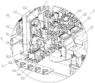
FIG. 3 is an enlarged view of a portion of FIG. 2;
FIG. 4 is a schematic structural view of a second angle portion of the present invention;
FIG. 5 is a partial enlarged view of B in FIG. 4;
in the figure, 1, a workbench; 2. a first motor mounting tool; 21. a support plate; 22. a limiting cavity; 23. a clamping block; 3. clamping and carrying the tool; 31. a first X-axis moving mechanism; 32. a first Z-axis moving mechanism; 33. a first Y-axis moving mechanism; 34. a clamping mechanism; 4. a gasket feeding mechanism; 5. a gasket carrying and pressing mechanism; 51. a support pillar; 52. a second Y-axis moving mechanism; 53. a second Z-axis moving mechanism; 54. a gasket suction mechanism; 55. a gasket pressing mechanism; 6. a clamp spring feeding mechanism; 7. a clamp spring mounting station; 71. a first longitudinal control mechanism; 72. a first slide rail; 73. installing a tool; 8. a clamp spring mounting mechanism; 81. a Z-direction control cylinder; 82. a second slider; 83. a second slide rail; 84. a click spring mechanism; 9. a visual inspection station; 91. a second longitudinal control mechanism; 92. a second slider; 93. a second slide rail; 94. a second motor mounting tool; 10. a visual detection mechanism; 101. fixing a column; 102. connecting blocks; 103. a detection device; 11. a blanking station; 111. a support frame; 112. a lateral control mechanism; 113. placing a tool; 12. a jump ring backflow mechanism is missed; 121. a third X-axis moving mechanism; 122. and (5) fixing the motor.
Detailed Description
In order to make the technical solution more clear to those skilled in the art, the technical solution of the present invention will be described in detail below with reference to fig. 1 to 5:
a kind of electric motor dress gasket and jump ring apparatus, including the work station 1, set up in the first electric motor that the work station 1 installs the frock 732 on the work station, set up in one side of 1 top of work station and locate at the centre gripping that the first electric motor installs frock 732 side and carries the frock 3, set up in the gasket feed mechanism 4 of one side on the work station 1, set up in the work station 1 and locate at gasket feed mechanism 4 side and carry the pressing mechanism 5 of gasket, set up in the jump ring feed mechanism 6 of one side on the work station 1, set up in the work station 1 and locate at jump ring installation station 7 of one side of jump ring feed mechanism 6, set up in the work station 1 and locate at gasket carry pressing mechanism 5 side jump ring installation mechanism 8 of one side, set up in the visual detection station 9 of one side end of the work station 1, set up in the visual detection mechanism 10 of one side of visual detection station 9, set up in the blanking station 11 of one side of visual detection mechanism 10, set up in the leak and beat the return mechanism 12 of the jump ring of one side end of the work station 1; the working principle is as follows: firstly, a motor is placed on a first motor installation tool 732, then the motor is transported to a first motor installation tool 732 below a gasket transporting and pressing-in mechanism 5 through a clamping and transporting mechanism, then a gasket loading mechanism 4 works, then the gasket transporting and pressing-in mechanism 5 sucks and places a gasket on the gasket loading mechanism 4 in the motor, then the gasket transporting and pressing-in mechanism 5 presses the gasket on the gasket, then a clamp spring loading mechanism 6 starts working, then the motor is transported to a clamp spring installation station 7 through the clamping and transporting tool 3 continuously, then the clamp spring is manually placed on the motor, then the clamp spring is installed in the motor through a clamp spring installation mechanism 8, then the motor with the gasket and the clamp spring installed is moved to a visual detection station 9 through the clamping and transporting tool 3, the visual detection mechanism 10 starts working to detect whether the gasket and the clamp spring are installed or not, if the gasket and the clamp spring are normally installed, blanking is carried out through a blanking station 11, if the gasket and the clamp spring is not installed, a product is manually placed on a missed-punching clamp spring backflow mechanism 12, and the installation process is repeated.
The first motor installation tool 732 comprises a support plate 21, limiting cavities 22 arranged on two sides above the support plate 21 and clamping blocks 23 symmetrically arranged on two sides above the limiting cavities 22, the support plate 21 is fixedly arranged on the workbench 1, the limiting cavities 22 are fixedly arranged above the support plate 21, the motor is placed in the middle of the clamping blocks 23 on the two sides, the clamping blocks 23 can clamp the motor in a limiting mode, and the limiting cavities 22 can also limit the motor in a limiting mode.
The structure of the clamping and carrying tool 3 is explained in detail below, the clamping and carrying tool 3 includes a first X-axis moving mechanism 31, a first Z-axis moving mechanism 32 disposed on the first X-axis moving mechanism 31, a first Y-axis moving mechanism 33 disposed on the first Z-axis moving mechanism 32, and a clamping mechanism 34 disposed on the first Z-axis moving mechanism 32, and the clamping and carrying tool 3 can drive the motor to move in the X direction, the Y direction and the Z direction, so as to meet the use requirements.
The gasket conveying and pressing mechanism 5 comprises a supporting column 51, a second Y-axis moving mechanism 52 arranged on the supporting column 51, second Z-axis moving mechanisms 53 arranged on the left side and the right side of the second Y-axis moving mechanism 52, a gasket suction mechanism 54 and a gasket pressing mechanism 55 which are respectively arranged on the second Z-axis moving mechanisms 53, wherein the end part of the gasket feeding mechanism 4 is arranged right below the gasket conveying and pressing mechanism 5; the gasket suction mechanism 54 can clamp the gasket on the gasket feeding mechanism 4 under the action of the second Y-axis moving mechanism 52 and the second Z-axis moving mechanism 53, and after the gasket is placed in the motor, the gasket is pressed by the gasket pressing mechanism 55.
The clamp spring mounting station 7 comprises a first longitudinal control mechanism 71, a first sliding block connected with the first longitudinal control mechanism 71, a first sliding rail 72 arranged below the first sliding block, and a mounting tool 73 arranged above the first sliding block, wherein the first sliding block is slidably mounted on the first sliding rail 72, can longitudinally move according to the position of the clamp spring mounting mechanism 8, and then can well limit the motor, so that the clamp spring mounting mechanism 8 can conveniently perform clamp spring punching operation on the first sliding block; the clamp spring mounting mechanism 8 comprises a Z-direction control cylinder 81, a second sliding block 82 connected with the Z-direction control cylinder 81, a second sliding rail 83 connected with the second sliding block 82, and a clamp spring punching mechanism 84 arranged below the second sliding block 82, wherein the second sliding block 82 is slidably mounted on the second sliding rail 83, and the Z-direction control cylinder 81 can drive the second sliding block 82 to move on the second sliding rail 83, so that the clamp spring punching mechanism 84 is driven to move, and thus the clamp spring on the motor is mounted.
The visual detection station 9 is arranged on one side of the clamp spring installation mechanism 8, the visual detection station 9 comprises a second longitudinal control mechanism 91, a third sliding block 92 connected with the second longitudinal control mechanism 91, a third sliding rail 93 arranged below the third sliding block 92, and a second motor installation tool 9 connected with the second longitudinal control mechanism 91, and the second longitudinal control mechanism 91 can drive the third sliding block 92 to slide on the third sliding rail 93, so that the movement is convenient for the visual detection mechanism 10 to detect a motor thereon; the visual detection mechanism 10 comprises a fixing column 101, a connecting block 102 fixedly connected with the fixing column 101 and a detection device 103 arranged on the connecting block 102, wherein the fixing column 101 is fixedly installed on the workbench 1, and the detection device 103 can detect whether a clamp spring and a gasket on the motor are installed or not.
The blanking station 11 comprises a support frame 111, a transverse control mechanism 112 arranged above the support frame 111, and a placing tool 113 connected with the transverse control mechanism 112, wherein the transverse control mechanism 112 is convenient for the clamping and carrying mechanism to better place the motor on the transverse control mechanism 112.
The missed-punching clamp spring backflow mechanism 12 comprises a third X-axis moving mechanism 121 and a motor fixing tool 122 slidably mounted on the third X-axis moving mechanism 121, namely, a product is placed on the third X-axis moving mechanism 121, and the third X-axis moving mechanism 121 works to enable a motor placed on the motor fixing tool 122 to return to one side of a motor feeding part, so that gasket or clamp spring installation can be completed subsequently.
Above-mentioned technical scheme has only embodied the utility model discloses technical scheme's preferred technical scheme, some changes that this technical field's technical personnel probably made to some parts wherein have all embodied the utility model discloses a principle belongs to within the protection scope of the utility model.
Claims (10)
1. The utility model provides a motor dress gasket and jump ring equipment, a serial communication port, including workstation (1), set up first motor installation frock (73) (2) on workstation (1), set up centre gripping transport frock (3) that just is located first motor installation frock (73) (2) one side in workstation (1) top one side, set up gasket feed mechanism (4) of one side on workstation (1), set up on workstation (1) and be located gasket feed mechanism (4) one side gasket transport mechanism (5), set up jump ring feed mechanism (6) of one side on workstation (1), set up jump ring installation station (7) that just is located jump ring feed mechanism (6) one side on workstation (1), set up on workstation (1) and be located jump ring installation mechanism (5) one side jump ring installation mechanism (8), set up visual detection station (9) of one side tip on workstation (1), set up visual detection mechanism (10) one side visual detection mechanism (10), set up visual detection mechanism (11) one side, set up the blanking mechanism (12) that the return current of one side on workstation (1).
2. The motor gasket and clamp spring device according to claim 1, wherein the first motor installation tool (73) (2) comprises a support plate (21), limiting cavities (22) arranged on two sides above the support plate (21), and clamping blocks (23) symmetrically arranged on two sides above the limiting cavities (22), the support plate (21) is fixedly installed on the workbench (1), and the limiting cavities (22) are fixedly installed above the support plate (21).
3. The motor gasket and clamp spring assembling device according to claim 2, wherein the clamping and carrying tool (3) comprises a first X-axis moving mechanism (31), a first Z-axis moving mechanism (32) arranged on the first X-axis moving mechanism (31), a first Y-axis moving mechanism (33) arranged on the first Z-axis moving mechanism (32), and a clamping mechanism (34) arranged on the first Z-axis moving mechanism (32).
4. The apparatus as claimed in claim 3, wherein the gasket carrying and pressing mechanism (5) comprises a supporting column (51), a second Y-axis moving mechanism (52) disposed on the supporting column (51), second Z-axis moving mechanisms (53) disposed on left and right sides of the second Y-axis moving mechanism (52), a gasket sucking mechanism (54) disposed on the second Z-axis moving mechanism (53), and a gasket pressing mechanism (55).
5. The motor gasket and clamp spring device according to claim 4, wherein the clamp spring mounting station (7) comprises a first longitudinal control mechanism (71), a first sliding block connected with the first longitudinal control mechanism (71), a first sliding rail (72) arranged below the first sliding block, and a mounting tool (73) arranged above the first sliding block, and the first sliding block is slidably mounted on the first sliding rail (72).
6. The motor gasket and clamp spring device as claimed in claim 5, wherein the clamp spring mounting mechanism (8) comprises a Z-direction control cylinder (81), a second sliding block (82) connected with the Z-direction control cylinder (81), a second sliding rail (83) connected with the second sliding block (82), and a clamp spring striking mechanism (84) arranged below the second sliding block (82), wherein the second sliding block (82) is slidably mounted on the second sliding rail (83).
7. The motor gasket and clamp spring mounting device according to claim 6, wherein the visual detection station (9) is disposed on one side of the clamp spring mounting mechanism (8), and the visual detection station (9) comprises a second longitudinal control mechanism (91), a third slide block (92) connected with the second longitudinal control mechanism (91), a third slide rail (93) disposed below the third slide block (92), and a second motor mounting tool (94) connected with the second longitudinal control mechanism (91).
8. The gasket and clamp spring device for the motor according to claim 7, wherein the visual detection mechanism (10) comprises a fixed column (101), a connecting block (102) fixedly connected with the fixed column (101), and a detection device (103) arranged on the connecting block (102), and the fixed column (101) is fixedly arranged on the workbench (1).
9. The motor gasket and clamp spring device according to claim 8, wherein the blanking station (11) comprises a support frame (111), a transverse control mechanism (112) arranged above the support frame (111), and a placing tool (113) connected with the transverse control mechanism (112).
10. The motor gasket and clamp spring device as claimed in claim 9, wherein the missed clamp spring reflow mechanism (12) comprises a third X-axis moving mechanism (121) and a motor fixing tool (122) slidably mounted on the third X-axis moving mechanism (121).
Priority Applications (1)
| Application Number | Priority Date | Filing Date | Title |
|---|---|---|---|
| CN202222368476.3U CN218352364U (en) | 2022-09-06 | 2022-09-06 | Motor gasket and clamp spring mounting equipment |
Applications Claiming Priority (1)
| Application Number | Priority Date | Filing Date | Title |
|---|---|---|---|
| CN202222368476.3U CN218352364U (en) | 2022-09-06 | 2022-09-06 | Motor gasket and clamp spring mounting equipment |
Publications (1)
| Publication Number | Publication Date |
|---|---|
| CN218352364U true CN218352364U (en) | 2023-01-20 |
Family
ID=84893190
Family Applications (1)
| Application Number | Title | Priority Date | Filing Date |
|---|---|---|---|
| CN202222368476.3U Active CN218352364U (en) | 2022-09-06 | 2022-09-06 | Motor gasket and clamp spring mounting equipment |
Country Status (1)
| Country | Link |
|---|---|
| CN (1) | CN218352364U (en) |
-
2022
- 2022-09-06 CN CN202222368476.3U patent/CN218352364U/en active Active
Similar Documents
| Publication | Publication Date | Title |
|---|---|---|
| CN106879243B (en) | Automatic assembly production line for power adapters | |
| CN210703444U (en) | Online battery cover pressing machine | |
| CN111384650A (en) | Double-vibration ultrasonic integrated machine | |
| CN113909861B (en) | Battery installation pressurize equipment | |
| CN218352364U (en) | Motor gasket and clamp spring mounting equipment | |
| CN110421637B (en) | Battery protection board production equipment | |
| CN213437905U (en) | Welding system | |
| CN212169345U (en) | Laser etching equipment and automatic production line | |
| CN211759211U (en) | Automatic spot welding device for copper foil of middle frame of mobile phone | |
| CN211072550U (en) | Automatic device for preassembling wiring support assembly | |
| CN208292229U (en) | Automatic blanking device | |
| CN202846157U (en) | Composite processing machine for numerical control punching and cutting | |
| CN111421831A (en) | Ultrasonic wave compression fittings and two supersound all-in-one that vibrate | |
| CN112122815A (en) | Welding system and module side plate welding method | |
| CN111421841A (en) | Automatic rubber plug assembling and detecting equipment | |
| CN216084668U (en) | Assembly machine of multi-P circuit breaker | |
| CN113171939B (en) | Electronic component point is glued and is pasted dress all-in-one | |
| CN215704854U (en) | Automatic assembling equipment for touch plate glass and PCBA (printed circuit board assembly) plate | |
| CN212761711U (en) | Radium-shine welding set of duplex position material loading | |
| CN212666725U (en) | Ultrasonic wave compression fittings and two supersound all-in-one that vibrate | |
| CN212352965U (en) | Automatic rubber plug assembling and detecting equipment | |
| CN217502211U (en) | Full-automatic pressfitting equipment frock and equipment | |
| CN219598458U (en) | Centering mechanism and flexible tool | |
| CN216912518U (en) | Chip board radium carving machine | |
| CN115673755A (en) | Instrument desk shell assembling equipment |
Legal Events
| Date | Code | Title | Description |
|---|---|---|---|
| GR01 | Patent grant | ||
| GR01 | Patent grant |