CN217175622U - Protection integration elevartor shaft operation platform - Google Patents
Protection integration elevartor shaft operation platform Download PDFInfo
- Publication number
- CN217175622U CN217175622U CN202123375903.2U CN202123375903U CN217175622U CN 217175622 U CN217175622 U CN 217175622U CN 202123375903 U CN202123375903 U CN 202123375903U CN 217175622 U CN217175622 U CN 217175622U
- Authority
- CN
- China
- Prior art keywords
- elevator shaft
- support frame
- platform
- protective
- operating platform
- Prior art date
- Legal status (The legal status is an assumption and is not a legal conclusion. Google has not performed a legal analysis and makes no representation as to the accuracy of the status listed.)
- Active
Links
Images


Abstract
The utility model discloses a protection integrated elevator shaft operating platform, which comprises a platform structure and a protection structure, wherein the platform structure is arranged in an elevator shaft, and the protection structure is arranged on the platform structure and is positioned at the opening of the elevator shaft; the platform structure comprises a support frame, a steel platform and a fixing structure, the support frame is located in the elevator shaft, the steel platform is arranged at the top of the support frame, and the fixing structure is arranged on the support frame and connected with a wall body. The utility model discloses set up the stable reliable fixing of platform structure in the elevator shaft of fixed knot structure, avoided drilling on the wall body and carried out the mode of fixing, the dismouting is more convenient to the operation of maintaining the wall body in the later stage has been avoided; the protective structure convenient to disassemble and assemble is arranged on the platform structure, the protective effect is achieved, the construction safety is guaranteed, the protective structure can be used independently, the applicability is strong, the application range can be effectively widened, and the cost is reduced.
Description
Technical Field
The utility model relates to a construction technical field, concretely relates to protection integration elevartor shaft operation platform.
Background
When the high-rise building is constructed, an elevator shaft operating platform needs to be erected, so that constructors can conveniently install and detach the template and work correspondingly. Generally adopt traditional console mode scaffold frame or steel pipe scaffold frame of encorbelmenting, but owing to need frequent dismouting, the construction degree of difficulty is great, the potential safety hazard defect such as big no longer uses, consequently a steel construction platform has appeared, does not need frequent dismouting, only need adopt the wall bolt to fix can, convenient and fast. But above-mentioned steel construction platform still has the wall bolt to destroy greatly to the structure, and the later stage needs to be reprocessed and has the shortcoming of seepage risk, lacks safeguard measure moreover equally, appears the potential safety hazard easily. The utility model provides a protection integration elevartor shaft operation platform solves above-mentioned problem.
SUMMERY OF THE UTILITY MODEL
The utility model provides a protection integration elevartor shaft operation platform adopts the clamp type fixed, avoids the fixed defect of bringing of drilling to be equipped with safeguard measure and guarantee construction safety.
The utility model provides a technical scheme that above-mentioned technical problem adopted is:
a protection integrated elevator shaft operating platform comprises a platform structure and a protection structure, wherein the platform structure is arranged in an elevator shaft, and the protection structure is arranged on the platform structure and is positioned at an opening of the elevator shaft;
the platform structure comprises a support frame, a steel platform and a fixing structure, the support frame is located in the elevator shaft, the steel platform is arranged at the top of the support frame, and the fixing structure is arranged on the support frame and connected with a wall body.
Further, protective structure comprises the protection network unit, the protection network unit includes skeleton and protection network, the protection network sets up on the skeleton.
Further, be equipped with on the skeleton and articulate hook and butt joint pipe, articulate the hook and establish in the skeleton inboard to be connected with the support frame, the butt joint pipe is established in the both sides of skeleton, and adjacent skeleton is through the butt joint union coupling.
Furthermore, the side surface of the framework is provided with a butt joint groove, and the butt joint pipe is positioned in the butt joint groove and connected through a locking bolt.
Furthermore, fixed knot constructs including vaulting pole and fixed arm, the vaulting pole is established in the bottom of support frame to the card is established on the floor of elevator well entrance to a cave, fixed arm swing joint is in the support frame middle part, and the card is established on the wall body.
Furthermore, the fixed arm is of a J-shaped structure, the inner end of the fixed arm is movably connected to the support frame, and the outer end of the fixed arm is clamped on the wall body.
Furthermore, the inner end of the fixing arm is provided with a sleeve, and the sleeve is connected to the support frame through a bolt.
Furthermore, the outer end of the fixed arm is provided with a locking rod, the locking rod is connected to the fixed arm through threads, the inner end of the locking rod is provided with a gasket, and the gasket is in contact with the wall surface.
Preferably, the support frame is a triangular frame, and criss-cross frame rods are arranged on the inner side of the support frame.
Preferably, a warning skirting board is arranged below the protective net.
The utility model discloses beneficial effect as follows:
the platform structure is stably and reliably fixed in the elevator shaft by the fixing structure, so that a fixing mode of drilling holes in the wall body is avoided, the disassembly and the assembly are more convenient, and the later maintenance operation on the wall body is avoided;
the protective structure convenient to disassemble and assemble is arranged on the platform structure, the protective effect is achieved, the construction safety is guaranteed, the protective structure can be used independently, the applicability is strong, the application range can be effectively widened, and the cost is reduced.
Drawings
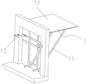
FIG. 1 is a schematic view of the usage state of the present invention;
FIG. 2 is a schematic view of the overall structure of the present invention;
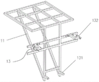
fig. 3 is a schematic view of the fixed state of the platform structure of the present invention;
FIG. 4 is a schematic view of the supporting frame of the present invention;
fig. 5 is a schematic structural view of the fixing arm of the present invention;
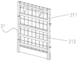
fig. 6 is a schematic view of the structure of the protection net unit of the present invention.
Reference numerals: 1-platform structure, 11-support frame, 12-steel platform, 13-fixing structure, 131-support rod, 132-fixing arm, 133-locking rod, 2-protective structure, 21-protective net unit, 211-framework and 212-protective net.
Detailed Description
The technical solutions in the embodiments of the present invention will be described clearly and completely with reference to the accompanying drawings, and obviously, the described embodiments are only some embodiments, not all embodiments, of the present invention. Based on the embodiments in the present invention, all other embodiments obtained by a person skilled in the art without creative work belong to the protection scope of the present invention.
In the description of this patent, it is to be understood that the terms "center," "upper," "lower," "front," "rear," "left," "right," "vertical," "horizontal," "top," "bottom," "inner," "outer," and the like are used in the orientations and positional relationships indicated in the drawings for the convenience of describing the patent and for the simplicity of description, and are not intended to indicate or imply that the referenced devices or elements must have a particular orientation, be constructed and operated in a particular orientation, and are not to be considered limiting of the patent.
As shown in fig. 1 and 2, the protection integrated elevator shaft operating platform comprises a platform structure 1 and a protection structure 2, wherein the platform structure 1 is arranged in an elevator shaft, and the protection structure 2 is arranged on the platform structure 1 and is positioned at an elevator shaft opening.
The utility model adopts a detachable connection mode to realize the installation of the platform structure 1, thereby not only ensuring the stability and safety of the installation, but also avoiding the subsequent maintenance and construction, saving the construction period and reducing the labor intensity; the protective structure 2 adopts a combined structure, is convenient to place and has strong applicability, and can be matched with a platform structure to be applicable and also can be independently applied to an elevator shaft opening.
As shown in fig. 3 and 4, the platform structure 1 includes a support frame 11, a steel platform 12 and a fixing structure 13, the support frame 11 is located in the elevator hoistway, the steel platform 12 is disposed on the top of the support frame 11, and the fixing structure 13 is movably connected to the support frame 11 and connected to the wall.
As shown in fig. 2 and 6, further, the protective structure 2 is composed of protective net units 21, different numbers of the protective net units 21 can be flexibly selected according to the size of the opening, each protective net unit 21 includes a framework 211 and a protective net 212, and the protective net 212 is disposed on the framework 211. The protective structure 2 can be arranged on the platform structure 1 in a matched mode, and can also be applied to an elevator shaft opening independently for safety protection.
As shown in fig. 6, further, the frame 211 is provided with a hook and a butt joint pipe, the hook is arranged inside the frame 211 and connected to the support frame 11, the butt joint pipe is arranged on two sides of the frame 211, and the adjacent frames 211 are connected by the butt joint pipe.
Preferably, the hanging hook and the framework 211 form a U-shaped groove, which is fastened on the supporting frame 11 and fastened at the opening. The fixing stability is ensured, and the effective protection effect is also achieved.
Furthermore, the side of the frame 211 is provided with a butt-joint groove, and the butt-joint pipe is located in the butt-joint groove and connected through a locking bolt. Adjacent protection net units 21 are connected by butt pipes.
As shown in fig. 3 and 4, further, the fixing structure 13 includes a support rod 131 and a fixing arm 132, the support rod 131 is disposed at the bottom of the support frame 11 and is clamped on a floor of the elevator shaft opening, and the fixing arm 132 is movably connected to the middle of the support frame 11 and is clamped on a wall. The stay bar 131 is supported on a floor slab, the two fixing arms 132 which are oppositely arranged are clamped on a wall body, so that the platform structure 1 is clamped at the opening of the elevator shaft of the corresponding floor, the two fixing arms 132 which are oppositely arranged can effectively avoid the transverse movement of the platform structure 1, and the stay bar 131 plays a supporting role, so that the stability of the state of the platform structure 1 is realized.
Further, the fixed arm 132 is a J-shaped structure, the inner end of the fixed arm is movably connected to the support frame 11, and the outer end of the fixed arm is clamped on the wall.
Further, the inner end of the fixing arm 132 is provided with a sleeve, and the sleeve is connected to the support frame 11 through a bolt.
Preferably, the supporting frame 11 is provided with locking holes at intervals, and the bolts on the sleeves are fixed in the locking holes, so as to ensure that the fixing arms 132 are in a stable state, and further ensure the safety of the platform structure 1.
As shown in fig. 5, further, the outer end of the fixed arm 132 is provided with a locking lever 133, the locking lever 133 is connected to the fixed arm 132 through a thread, and the inner end of the locking lever 133 is provided with a gasket, and the gasket is in contact with a wall surface. When the locking device is used, the locking rod 133 retracts firstly, the distance between the clamping ports of the fixing arm 132 is guaranteed, after the platform structure 1 is placed in place, the position of the fixing arm 132 is adjusted, the fixing arm 132 and the support frame 11 are respectively located on two sides of a wall body, then the fixing arm 132 is locked on the support frame 11 through bolts, and then the locking rod 133 is adjusted to extend out, so that the inner end of the locking rod is in contact with the wall surface, and the locking rod and the support frame 11 clamp the platform structure 1 on the wall body.
Preferably, the supporting frame 11 is a triangular frame, and criss-cross frame rods are arranged on the inner side of the supporting frame 11.
Preferably, a warning skirting board is arranged below the protective net 212.
The utility model discloses a use method as follows: carry out platform structure 1's equipment earlier, adopt lifting device to hoist platform structure 1 to construction position department in the elevartor shaft after the completion, prop vaulting pole 131 and adjust fixed arm 132 and carry out the card solid on the floor, then it is fixed to carry out protective structure 2's installation, carry out corresponding operation after the completion and use, after the construction is accomplished, demolish protective structure 2, loosen fixed arm 132 and hoist platform structure 1 to next construction position, continue to be under construction according to above-mentioned operation.
It is obvious to a person skilled in the art that the invention is not restricted to details of the above-described exemplary embodiments, but that it can be implemented in other specific forms without departing from the spirit or essential characteristics of the invention. The present embodiments are therefore to be considered in all respects as illustrative and not restrictive, the scope of the invention being indicated by the appended claims rather than by the foregoing description, and all changes which come within the meaning and range of equivalency of the claims are therefore intended to be embraced therein, and any reference signs in the claims are not to be construed as limiting the claim concerned.
Claims (10)
1. A protection integrated elevator shaft operating platform is characterized by comprising a platform structure (1) and a protection structure (2), wherein the platform structure (1) is arranged in an elevator shaft, and the protection structure (2) is arranged on the platform structure (1) and is positioned at an elevator shaft opening;
the platform structure (1) comprises a support frame (11), a steel platform (12) and a fixing structure (13), the support frame (11) is located in an elevator shaft, the steel platform (12) is arranged at the top of the support frame (11), and the fixing structure (13) is arranged on the support frame (11) and connected with a wall body.
2. The protective integrated elevator shaft operating platform of claim 1, wherein: protective structure (2) comprise protection network unit (21), protection network unit (21) includes skeleton (211) and protection network (212), protection network (212) set up on skeleton (211).
3. The integrated elevator shaft operating platform of claim 2, wherein: be equipped with on skeleton (211) and articulate hook and butt joint pipe, articulate the hook and establish in skeleton (211) inboard to be connected with support frame (11), the butt joint pipe is established in the both sides of skeleton (211), and adjacent skeleton (211) are through the butt joint union coupling.
4. A protective integrated elevator shaft operating platform according to claim 3, wherein: the side surface of the framework (211) is provided with a butt joint groove, and the butt joint pipes are positioned in the butt joint groove and connected through locking bolts.
5. The protective integrated elevator shaft operating platform of claim 1, wherein: fixed knot constructs (13) including vaulting pole (131) and fixed arm (132), the bottom at support frame (11) is established in vaulting pole (131) to the card is established on the floor of elevator well entrance to a cave, fixed arm (132) swing joint is in support frame (11) middle part, and the card is established on the wall body.
6. The protective integrated elevator shaft operating platform of claim 5, wherein: the fixed arm (132) is of a J-shaped structure, the inner end of the fixed arm is movably connected to the support frame (11), and the outer end of the fixed arm is clamped on a wall body.
7. The integrated protective elevator shaft operating platform of claim 6, wherein: the inner end of the fixed arm (132) is provided with a sleeve, and the sleeve is connected to the support frame (11) through a bolt.
8. The integrated protective elevator shaft operating platform of claim 6, wherein: the outer end of fixed arm (132) is equipped with locking lever (133), locking lever (133) pass through threaded connection on fixed arm (132), the inner of locking lever (133) is equipped with the gasket, the gasket contacts with the wall.
9. The protective integrated elevator shaft operating platform of claim 1, wherein: the support frame (11) is a triangular frame, and criss-cross frame rods are arranged on the inner side of the support frame (11).
10. The protective integrated elevator shaft operating platform of claim 2, wherein: and a warning skirting board is arranged below the protective net (212).
Priority Applications (1)
| Application Number | Priority Date | Filing Date | Title |
|---|---|---|---|
| CN202123375903.2U CN217175622U (en) | 2021-12-30 | 2021-12-30 | Protection integration elevartor shaft operation platform |
Applications Claiming Priority (1)
| Application Number | Priority Date | Filing Date | Title |
|---|---|---|---|
| CN202123375903.2U CN217175622U (en) | 2021-12-30 | 2021-12-30 | Protection integration elevartor shaft operation platform |
Publications (1)
| Publication Number | Publication Date |
|---|---|
| CN217175622U true CN217175622U (en) | 2022-08-12 |
Family
ID=82730943
Family Applications (1)
| Application Number | Title | Priority Date | Filing Date |
|---|---|---|---|
| CN202123375903.2U Active CN217175622U (en) | 2021-12-30 | 2021-12-30 | Protection integration elevartor shaft operation platform |
Country Status (1)
| Country | Link |
|---|---|
| CN (1) | CN217175622U (en) |
-
2021
- 2021-12-30 CN CN202123375903.2U patent/CN217175622U/en active Active
Similar Documents
| Publication | Publication Date | Title |
|---|---|---|
| CN201598820U (en) | Single point suspension external hanging bracket | |
| CN213329955U (en) | Flower basket diagonal rod type overhanging scaffold | |
| CN214786179U (en) | Instrument formula level safety net of encorbelmenting | |
| CN217175622U (en) | Protection integration elevartor shaft operation platform | |
| CN206667042U (en) | Bridge expanssion joint installation and adjustment instrument | |
| CN211689948U (en) | Suspension operation platform device for construction of suspension cable at tower part of cable-stayed bridge | |
| CN211173007U (en) | Novel tripod of encorbelmenting | |
| CN211470603U (en) | Telescopic tower crane passageway | |
| CN206034875U (en) | Supplementary installation swing arm formula tower crane instrument roof beam hanging flower basket device | |
| CN213329975U (en) | Steel pull rod hanging and pulling overhanging bearing steel beam structure | |
| CN204038917U (en) | Dismountable external hanging service platform | |
| CN212101748U (en) | Tower crane attaches wall operation platform device | |
| CN210798251U (en) | But scaffold of automatically regulated height | |
| CN111997383A (en) | Construction is with platform of unloading | |
| CN114030977B (en) | Hoisting auxiliary device for rapidly installing angle steel bracket of pavement of railway bridge deck system | |
| CN218815124U (en) | Hanging basket device for erecting on high-rise building slope roof | |
| CN114278071B (en) | Climbing frame for building construction | |
| CN211949530U (en) | Climbing frame is with hanging a truss | |
| CN211286560U (en) | Spherical node suspension adjustable operation platform | |
| CN214192350U (en) | Tower crane frame structure | |
| CN214885646U (en) | Material platform drawknot connecting piece | |
| CN218668433U (en) | Operating platform for building construction of anti-video wall of house | |
| CN210396074U (en) | Lifting point truss and attached lifting scaffold thereof | |
| CN215167932U (en) | Flower basket pull rod type hanging scaffold support | |
| CN217711628U (en) | Channel steel cantilever support template supporting device |
Legal Events
| Date | Code | Title | Description |
|---|---|---|---|
| GR01 | Patent grant | ||
| GR01 | Patent grant |