CN216762300U - Facial mask dress holds in palm device - Google Patents
Facial mask dress holds in palm device Download PDFInfo
- Publication number
- CN216762300U CN216762300U CN202123125620.2U CN202123125620U CN216762300U CN 216762300 U CN216762300 U CN 216762300U CN 202123125620 U CN202123125620 U CN 202123125620U CN 216762300 U CN216762300 U CN 216762300U
- Authority
- CN
- China
- Prior art keywords
- sliding chute
- sliding groove
- chute
- station
- cylinder
- Prior art date
- Legal status (The legal status is an assumption and is not a legal conclusion. Google has not performed a legal analysis and makes no representation as to the accuracy of the status listed.)
- Active
Links
Images


Abstract
The utility model relates to a facial mask supporting device, which comprises a workbench, wherein a supporting station is arranged on the workbench; a frame is arranged at the upper part of the loading station, a discharging frame is obliquely arranged at the upper part of the frame, and one end of the discharging frame is oppositely provided with a material sucking station; a blanking structure is further arranged between the material sucking station and the end part of the material placing frame, the blanking structure comprises a first sliding chute, and the lower part of the first sliding chute is sequentially communicated with a second sliding chute and a third sliding chute; a first detection photoelectric part is vertically arranged on one side of the second sliding chute and one side of the third sliding chute; a first movable baffle, a second sliding baffle and a third movable baffle are sequentially inserted among the first sliding chute, the second sliding chute and the third sliding chute, and one sides of the three movable baffles are connected with a driving cylinder; the lower part of the third chute is communicated with the guide chute; the guide groove is opposite to the support mounting station. This facial mask dress holds in palm device realizes that machinery dress holds in the palm facial mask efficient, links up smoothly from the blanking to discharge mechanism, and each subassembly modularized design satisfies the customer and to product individualized needs and be convenient for install and maintain.
Description
Technical Field
The utility model relates to the technical field of packaging facilities, in particular to a mask holding device.
Background
With the continuous progress of society, the packaging industry has been rapidly developed. Different products need to be equipped with different packaging machines. One of them is a mask product. In the production process of the mask, the mask needs to be subpackaged and put into a tray for pasteurization. At present, people insert facial mask into a tray through manual facial mask split charging, so that great manpower and material resources are consumed, time consumption is long, and overall production efficiency is greatly influenced.
Disclosure of Invention
The technical problem to be solved by the utility model is as follows: in order to solve the problems existing in the prior art, the mask loading and supporting device is provided, the mechanical loading and supporting efficiency is high, the connection from the blanking to the discharging mechanism is smooth, and the modularized design of each component meets the individual requirements of customers on products and is convenient to install and maintain.
The technical scheme adopted by the utility model for solving the technical problems is as follows: a facial mask supporting device comprises a workbench, wherein supporting stations are arranged on the workbench in parallel; a frame is arranged at the upper part of the loading station, a discharging frame is obliquely arranged at the upper part of the frame, and a material sucking station is arranged at one end of the discharging frame oppositely; a blanking structure is further arranged between the material sucking station and the end part of the material placing frame, the blanking structure comprises a first sliding groove, and the lower part of the first sliding groove is sequentially communicated with a second sliding groove and a third sliding groove; a first detection photoelectric part is vertically arranged on one side of the second sliding groove and one side of the third sliding groove; a first movable baffle, a second movable baffle and a third movable baffle are sequentially inserted among the first sliding chute, the second sliding chute and the third sliding chute, and one side of the first movable baffle, one side of the second movable baffle and one side of the third movable baffle are fixedly connected with a driving cylinder; the lower part of the third chute is communicated with the guide chute; the guide groove is opposite to the support mounting station.
Further limiting, in the above technical solution, the tray loading station includes a silent linear driving module, a guide rail and a tray; the lower part of the tray is arranged on the guide rail in a sliding manner, and the mute linear driving module is fixedly arranged on one side of the workbench; the design can control the sliding operation of the tray on the guide rail through the mute linear driving module, when the tray moves to the lower end of the guide groove, the discharging and the supporting can be realized, and then the mute linear driving module controls the tray to move a unit to continue supporting until the units on the tray are fully filled.
Further limiting, in the technical scheme, the material suction station comprises a support, a material suction cylinder and a sucker; the sucking cylinder is fixedly arranged on the bracket, and the sucking disc is arranged at the end part of the sucking cylinder; the blanking operation is carried out after the upper surface film of the material placing frame is adsorbed to the upper end of the first sliding groove through the material sucking station.
Further, in the above technical scheme, a material pressing assembly is further arranged on the other side of the second chute opposite to the third chute; the material pressing assembly comprises a first material pressing cylinder, a second material pressing cylinder and a material pressing sheet; the first material pressing cylinder is arranged on one side of the second material pressing cylinder; the material pressing sheet is fixedly arranged at the telescopic end of the second material pressing cylinder; the design is to prevent the mask product from being accumulated at the port of the guide groove, and the mask product can be quickly pressed into the corresponding filling unit in the tray through the material pressing component.
Further limiting, in the above technical solution, the upper part of the frame is also connected with the control panel through a connecting rod; the state schematic diagram of each station can be displayed through the control screen; the control operation of operating personnel is facilitated.
Further limiting, in the above technical scheme, a feeding platform is further arranged on one side of the workbench; therefore, the operation of placing the mask product on the placing frame can be conveniently carried out by operators.
Further, in the above technical solution, the first sliding chute, the second sliding chute, the third sliding chute and the guide groove are of an integral structure; the strength of the whole blanking mechanism can be improved.
Further prescribe that, among the above technical scheme, the blowing frame on parallel arrangement a plurality of transfer chains, the transfer chain fill facial mask product in.
The utility model has the beneficial effects that: the utility model provides a facial mask supporting device, which realizes high efficiency of mechanically supporting facial masks, is smooth in connection from blanking to a discharging mechanism, meets the individual requirements of customers on products through modular design of all components, and is convenient to install and maintain.
Drawings
In order to more clearly illustrate the embodiments or technical solutions in the prior art of the present invention, the drawings used in the description of the embodiments or prior art will be briefly described below, it is obvious that the drawings in the following description are only some embodiments described in the present application, and other drawings can be obtained by those skilled in the art without creative efforts.
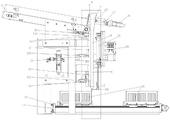
FIG. 1 is a schematic structural view of the present invention;
FIG. 2 is a side view of the structure of FIG. 1;
FIG. 3 is an enlarged schematic view of the structure at A in FIG. 2;
FIG. 4 is a schematic structural view of a palletizing station;
fig. 5 is an assembly view of the guide rail and the silent linear drive module.
The reference numbers in the drawings are: 1. the automatic feeding device comprises a workbench, 2, a loading station, 3, a frame, 4, a feeding frame, 5, a material sucking station, 6, a blanking mechanism, 7, a first sliding groove, 8, a second sliding groove, 9, a third sliding groove, 10, a first detection photoelectric device, 11A, a first movable baffle, 11B, a second movable baffle, 11C, a third movable baffle, 12, a driving cylinder, 13, a guide groove, 14, a mute linear driving module, 15, a guide rail, 16, a tray, 17, a support, 18, a material sucking cylinder, 19, a sucker, 20, a first material pressing cylinder, 21, a second material pressing cylinder, 22, a material pressing sheet, 23, a connecting rod, 24, a control screen, 25, a feeding platform, 26, a conveying line, 27, a servo motor, 28, a second detection photoelectric device, 29, a third detection photoelectric device, 30, a fourth detection photoelectric device, 31, a positioning sheet, 32 and a tray cylinder.
Detailed Description
In order to make the technical problems, technical solutions and advantageous effects solved by the present invention more clearly apparent, the present invention is further described in detail below with reference to the accompanying drawings and embodiments. It should be understood that the specific embodiments described herein are merely illustrative of the utility model and are not intended to limit the utility model.
In this application, drive actuating cylinder 12, control panel 24, first material cylinder 20, sucking disc 19, first detection photoelectricity 10, second material cylinder 21, silence straight line drive module 14 and inhale material cylinder 18 and all match the installation and use after directly purchasing from the market according to specific model.
In the application, one side of a first movable baffle plate 11A, one side of a second sliding baffle plate 11B and one side of a third movable baffle plate 11C are connected with driving cylinders 12 of the same type, and the opening or closing of each movable baffle plate is realized through the extension and retraction of the driving cylinders 12; in the application, the driving cylinder 12 can be selected from an ultra-thin Asia Deck cylinder SDA 25X 65S, a three-axis Asia Deck cylinder TCM 32X 25S, SMC single-rod double-acting non-rotation cylinder and the like.
The first detecting photoelectricity 10 can select diffuse reflection photoelectricity-Weck GTB 6-N1212; the mute linear driving module 14 is connected with the servo motor 27, and a standard 80 series alternating current servo motor can be selected.
As shown in the figures 1-5, the facial mask supporting device comprises a workbench 1, wherein supporting stations 2 are arranged on the workbench 1 in parallel; a frame 3 is arranged at the upper part of the loading station 2, a discharging frame 4 is obliquely arranged at the upper part of the frame 3, and a material sucking station 5 is oppositely arranged at one end of the discharging frame 4; a blanking structure is further arranged between the material sucking station 5 and the end part of the material placing frame 4, the blanking mechanism 6 comprises a first sliding chute 7, and the lower part of the first sliding chute 7 is sequentially communicated with a second sliding chute 8 and a third sliding chute 9; a first detection photoelectric device 10 is vertically arranged on one side of the second sliding chute 8 and one side of the third sliding chute 9; a first movable baffle 11A, a second movable baffle 11B and a third movable baffle 11C are sequentially inserted among the first chute 7, the second chute 8 and the third chute 9, and one side of the first movable baffle 11A, one side of the second movable baffle 11B and one side of the third movable baffle 11C are fixedly connected with a driving cylinder 12; the lower part of the third chute 9 is communicated with a guide groove 13; the guide groove 13 is opposite to the tray mounting station 2.
The tray loading station 2 comprises a mute linear driving module 14, a guide rail 15 and a tray 16; the lower part of the tray 16 is arranged on the guide rail 15 in a sliding way, and the mute linear driving module 14 is fixedly arranged on one side of the worktable 1. The material sucking station 5 comprises a support 17, a material sucking cylinder 18 and a sucker 19; the material suction cylinder 18 is fixedly arranged on the bracket 17, and the sucking disc 19 is arranged at the end part of the material suction cylinder 18. A material pressing component is further arranged on the other side, opposite to the second sliding chute 8 and the third sliding chute 9; the material pressing component comprises a first material pressing cylinder 20, a second material pressing cylinder 21 and a material pressing sheet 22; the first material pressing cylinder 20 is arranged on one side of the second material pressing cylinder 21; the material pressing sheet 22 is fixedly arranged at the telescopic end of the second material pressing cylinder 21. The upper part of the frame 3 is also connected to a control panel 24 by a link 23. A feeding platform 25 is arranged on one side of the workbench 1. The first sliding chute 7, the second sliding chute 8, the third sliding chute 9 and the guide groove 13 are of an integral structure. A plurality of conveying lines 26 are arranged on the material placing frame 4 in parallel, and the conveying lines 26 are filled with mask products.
The loading station 2 comprises a servo motor 27, and the servo motor 27 is positioned at the end part of the guide rail 15; the mute linear driving module 14 is positioned at one side of the servo motor 27; a second detection photoelectric device 28, a third detection photoelectric device 29 and a fourth detection photoelectric device 30 are sequentially arranged on the guide rail 15 along the length direction; a positioning block 31 is arranged on a tray cylinder 32 at the lower part of the tray 16, and the movement of the positioning block 31 is sensed by the second detection photo 28, the third detection photo 29 and the fourth detection photo 30, so that the specific position movement of the tray 16 can be controlled conveniently.
In the application, the operation principle of the palletizing station 2 is that the palletizing station 2 comprises a mute linear driving module 14, a guide rail 15 and a tray 16; the lower part of the tray 16 is arranged on the guide rail 15 in a sliding way, and the mute linear driving module 14 is fixedly arranged on one side of the workbench 1; in the actual operation process, the mute linear driving module 14 drives the tray 16 to slide on the guide rail 15, when the guide groove 13 inputs a product into one unit in the tray 16, the mute linear driving module 14 controls the tray 16 to slide one unit to one side to realize the filling again until the tray 16 is filled, and when the tray is filled, the mute linear driving module 14 controls the tray 16 to move to one end of the guide rail 15, so that the tray 16 is manually replaced.
In the present application, the operating principle of the suction station 5 is as follows: the material sucking station 5 comprises a support 17, a material sucking cylinder 18 and a sucker 19; the material suction cylinder 18 is fixedly arranged on the bracket 17, and the sucking disc 19 is arranged at the end part of the material suction cylinder 18; when the first detection photoelectric device 10 on the first chute 7 detects that no mask material exists, the operation of the material suction cylinder 18 is controlled, the material suction cylinder 18 extends out of the suction cup 19, and the suction cup 19 retracts to the upper end of the first chute 7 after sucking the mask material; the sucking disc 19 stops adsorbing, and the facial mask material can automatically fall into the first chute 7.
In this application, the principle of operation of blanking structure is as follows: the blanking mechanism 6 comprises a first chute 7, and the lower part of the first chute 7 is sequentially communicated with a second chute 8 and a third chute 9; a first detection photoelectric device 10 is vertically arranged on one side of the second sliding chute 8 and one side of the third sliding chute 9; a first movable baffle 11A, a second movable baffle 11B and a third movable baffle 11C are sequentially inserted among the first chute 7, the second chute 8 and the third chute 9, and one side of the first movable baffle 11A, one side of the second movable baffle 11B and one side of the third movable baffle 11C are fixedly connected with a driving cylinder 12; the lower part of the third chute 9 is communicated with a guide groove 13; the guide groove 13 is opposite to the tray mounting station 2.
The first detection photoelectric device 10 on the first chute 7 can detect whether a facial mask product exists in the first chute, when no facial mask material exists, the operation of the material suction station 5 can be controlled, and the material suction station 5 adsorbs the facial mask product from each conveying line 26 on the material placing frame 4 through the sucking disc 19 and then places the facial mask product on the material placing frame to the material placing mechanism for material placing; first spout 7 can fall into at first in the blanking process, when confirming the facial mask material, drive actuating cylinder 12 can control first adjustable fender 11A and open the back and fall into second spout 8, when first detection photoelectricity 10 on the second spout 8 detects there is the facial mask material in the second spout 8, can open through drive actuating cylinder 12 control second adjustable fender 11B, open the back, the facial mask material can fall into the third spout, fall into in the guide way 13 after the same operation, pack in the unit on the leading-in tray 16 at last.
In this application, the operating principle of pressing the material subassembly is as follows: the material pressing assembly comprises a first material pressing cylinder 20, a second material pressing cylinder 21 and a material pressing sheet 22; the first material pressing cylinder 20 is arranged on one side of the second material pressing cylinder 21; the material pressing sheet 22 is fixedly arranged at the telescopic end of the second material pressing cylinder 21. The first pressing cylinder 20 pushes the second pressing cylinder 21 to one side of the guide groove 13 when running, and when the second pressing cylinder 21 is pushed to the right position, the pressing sheet 22 runs downwards to press the mask material at the port of the guide groove 13 into the unit in the tray 16; therefore, the mask material can be prevented from being adhered to the end opening of the guide groove 13, and the rapid stripping operation is facilitated.
In the present application, the operation principle of the mute linear driving module 14 is as follows: the control screen 24 input signal gives PLC, and PLC gives servo motor 27 again to the signal, and servo motor 27's signal is passed to silence linear drive module 14, and the axle makes a round tray station move 80 ~ 100mm in the silence linear drive module 14. When the positioning sheet 31 is located at the origin point of the tray 16 during the second detection photoelectric sensor 28, the upper computer program controls the mute linear driving module 14 to rotate, so that the positioning sheet 31, namely the whole tray, moves to the third detection photoelectric sensor 29, and the first grid station of the tray 16 is just located below the guide groove 13 when the positioning sheet 31 is located at the third detection photoelectric sensor 29. Meanwhile, the third detection photoelectric sensor 29 returns a signal to the upper computer, the program of the upper computer changes, and the shaft of the mute linear driving module 14 rotates for turns according to the distance that the tray 16 needs to move. After the first grid tray loading station is used for loading the facial mask, the upper computer program controls the mute linear driving module 14 to move the tray 16 to the second tray loading station, and the rest is done until the last grid station of the tray 16 is completely loaded when the positioning sheet 31 is at the position of the fourth detection photoelectric 30, the fourth detection photoelectric 30 signal returns to the upper computer, and the upper computer program changes to control the whole tray 16 to return to the original point for manually replacing the tray 16.
The operation principle of the mask holding device is as follows:
first, the operator can mount the loading platform 25 and then sequentially place the mask products in the respective transfer lines 26. Because the slope setting of blowing frame 4, so the facial mask product can flow the one end that blowing frame 4 height above sea level is low and get into and inhale material station 5, when the first detection photoelectricity 10 of first spout 7 detects no material, inhale material cylinder 18 and drive the facial mask material of 19 suction required quantity of sucking disc and get into first spout 7, the first detection photoelectricity 10 of first spout 7 detects the correct quantity of material and the photoelectricity of second spout 8 detects 10 when the facial mask material is empty, first adjustable fender 11A opens through the drive of actuating cylinder 12 drive, the facial mask material gets into second spout 8, second spout 8 plays buffering and material storage effect. When the first detection photoelectric device 10 of the third chute 9 detects that the mask material is empty and the photoelectric detection on the second chute 8 detects that the mask material is empty, the second movable baffle 11B opens the mask material to enter the third chute 9. After the tray 16 of the loading station 2 is driven to reach a designated position by the mute linear driving module 14, the third movable baffle 11C is opened, and the first material pressing cylinder 20 pushes the second material pressing cylinder 21 to enable the material pressing sheet 22 to enter the guide groove 13 for downward material pressing, so that the material completely enters the tray 16 station. When the silent linear drive module 14 detects that the tray 16 is full, the third movable fence 11C stops operating and the tray 16 is returned to the origin via the guide rail 15 to perform manual tray change of the tray 16.
The above description is only for the preferred embodiment of the present invention, but the scope of the present invention is not limited thereto, and any person skilled in the art should be considered to be within the scope of the present invention, and the technical solutions and the utility model concepts of the present invention are equivalent to or changed within the scope of the present invention.
Claims (8)
1. The utility model provides a facial mask dress holds in palm device which characterized in that: the device comprises a workbench, wherein support stations are arranged on the workbench in parallel; a frame is arranged at the upper part of the loading station, a discharging frame is obliquely arranged at the upper part of the frame, and a material sucking station is arranged at one end of the discharging frame oppositely; a blanking structure is further arranged between the material sucking station and the end part of the material placing frame and comprises a first sliding groove, and the lower part of the first sliding groove is sequentially communicated with a second sliding groove and a third sliding groove; a first detection photoelectric part is vertically arranged on one side of the second sliding groove and one side of the third sliding groove; a first movable baffle, a second movable baffle and a third movable baffle are sequentially inserted among the first sliding chute, the second sliding chute and the third sliding chute, and one side of the first movable baffle, one side of the second movable baffle and one side of the third movable baffle are fixedly connected with a driving cylinder; the lower part of the third sliding chute is communicated with the guide chute; the guide groove is opposite to the support mounting station.
2. A mask pack holding device according to claim 1, wherein: the tray loading station comprises a mute linear driving module, a guide rail and a tray; the lower part of the tray is arranged on the guide rail in a sliding mode, and the mute linear driving module is fixedly arranged on one side of the workbench.
3. A mask pack holding device according to claim 1, wherein: the material sucking station comprises a support, a material sucking cylinder and a sucker; the material suction cylinder is fixedly arranged on the support, and the sucker is arranged at the end part of the material suction cylinder.
4. A mask pack holding device according to claim 1, wherein: a material pressing component is further arranged on the other side, opposite to the second sliding groove and the third sliding groove, of the second sliding groove; the material pressing assembly comprises a first material pressing cylinder, a second material pressing cylinder and a material pressing sheet; the first material pressing cylinder is arranged on one side of the second material pressing cylinder; the material pressing sheet is fixedly arranged at the telescopic end of the second material pressing cylinder.
5. A mask cartridge according to claim 1, wherein: the upper part of the frame is also connected with a control screen through a connecting rod.
6. A mask pack holding device according to claim 1, wherein: and a feeding platform is arranged on one side of the workbench.
7. A mask pack holding device according to claim 1, wherein: the first sliding groove, the second sliding groove, the third sliding groove and the guide groove are of an integrated structure.
8. A mask cartridge according to claim 1, wherein: the material placing frame is provided with a plurality of conveying lines in parallel, and the conveying lines are filled with mask products.
Priority Applications (1)
| Application Number | Priority Date | Filing Date | Title |
|---|---|---|---|
| CN202123125620.2U CN216762300U (en) | 2021-12-13 | 2021-12-13 | Facial mask dress holds in palm device |
Applications Claiming Priority (1)
| Application Number | Priority Date | Filing Date | Title |
|---|---|---|---|
| CN202123125620.2U CN216762300U (en) | 2021-12-13 | 2021-12-13 | Facial mask dress holds in palm device |
Publications (1)
| Publication Number | Publication Date |
|---|---|
| CN216762300U true CN216762300U (en) | 2022-06-17 |
Family
ID=81967928
Family Applications (1)
| Application Number | Title | Priority Date | Filing Date |
|---|---|---|---|
| CN202123125620.2U Active CN216762300U (en) | 2021-12-13 | 2021-12-13 | Facial mask dress holds in palm device |
Country Status (1)
| Country | Link |
|---|---|
| CN (1) | CN216762300U (en) |
-
2021
- 2021-12-13 CN CN202123125620.2U patent/CN216762300U/en active Active
Similar Documents
| Publication | Publication Date | Title |
|---|---|---|
| CN201961567U (en) | Automatic bag feeding machine | |
| CN105676108A (en) | Automatic detection system for circuit boards | |
| CN209698378U (en) | Battery of mobile phone automatic assembling | |
| CN105539955A (en) | Automatic instruction book packaging system | |
| CN109607155B (en) | Gasket gluing equipment | |
| CN102431680A (en) | Automatic bag supplying machine | |
| CN110550262A (en) | Button cell detects mark packaging all-in-one machine | |
| CN204271184U (en) | The materiel delivery system of fluid injection packaging machine | |
| CN216762300U (en) | Facial mask dress holds in palm device | |
| CN114212306A (en) | Facial mask dress holds in palm device | |
| CN112357197A (en) | Novel intelligent frozen food packaging system and method | |
| CN117141838A (en) | Full-automatic bag feeding and packaging equipment | |
| CN210338407U (en) | Marinated egg packaging, arranging and feeding mechanism | |
| CN111942665A (en) | Automatic bagging machine | |
| CN214241468U (en) | Automatic production line for barreled snail rice noodles | |
| CN210555813U (en) | Automatic packaging production device for nursing pads | |
| CN112605003B (en) | Multi-station lithium battery cap air tightness detection device and implementation method thereof | |
| CN208439474U (en) | Packing device is selected in a kind of contact automatically | |
| CN114194434A (en) | Powder filling baling line feed supplement device | |
| CN219820457U (en) | Automatic feeding device for material tray | |
| CN211254103U (en) | Biscuit automatic packaging machine's bottle lid loading attachment | |
| CN215422559U (en) | Fish reason material machine | |
| CN110395435B (en) | Automatic packaging production device and process for nursing pad | |
| CN212712700U (en) | Automatic filling, capping and labeling production line | |
| CN212531442U (en) | Automatic charging equipment for energy storage devices |
Legal Events
| Date | Code | Title | Description |
|---|---|---|---|
| GR01 | Patent grant | ||
| GR01 | Patent grant |