CN216631663U - Paster precision detection machine - Google Patents
Paster precision detection machine Download PDFInfo
- Publication number
- CN216631663U CN216631663U CN202122937118.5U CN202122937118U CN216631663U CN 216631663 U CN216631663 U CN 216631663U CN 202122937118 U CN202122937118 U CN 202122937118U CN 216631663 U CN216631663 U CN 216631663U
- Authority
- CN
- China
- Prior art keywords
- detection
- linear module
- mentioned
- transfer
- support
- Prior art date
- Legal status (The legal status is an assumption and is not a legal conclusion. Google has not performed a legal analysis and makes no representation as to the accuracy of the status listed.)
- Withdrawn - After Issue
Links
Images


Landscapes
- Investigating Materials By The Use Of Optical Means Adapted For Particular Applications (AREA)
Abstract
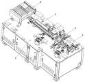
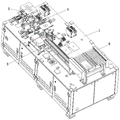
本实用新型公开了一种贴片精度检测机,包括上料平台、上料搬臂、下检测机构、移载平台、上检测机构及下料机构,上料平台、下检测机构及移载平台沿直线方向间隔设置在机台上;上检测机构架设在移载平台的上方;上料搬臂从上料平台上搬取物料后从下检测机构上方直线移动,经下检测机构检测物料底部,并将物料放置在移载平台上,移载平台带动物料在上检测机构下发直线移动,经上检测机构对物料表面进行检测;下料机构设置在上检测机构的侧部,检测后的物料经下料机构下料。本实用新型以四个CCD镜头可拍摄的圆形检测面为四个检测基点,以检测基点的精度实现偏光片贴合正面贴合精度检测,且有效地覆盖了整个贴附面,且集成有上下两贴附面检测功能。

The utility model discloses a patch precision testing machine, which comprises a loading platform, a loading arm, a lower detection mechanism, a transfer platform, an upper detection mechanism and an unloading mechanism, a loading platform, a lower detection mechanism and a transfer platform It is arranged on the machine table at intervals along the linear direction; the upper detection mechanism is erected above the transfer platform; the loading arm moves the material from the loading platform and moves linearly above the lower detection mechanism, and the bottom of the material is detected by the lower detection mechanism. The material is placed on the transfer platform, and the transfer platform drives the material to move in a straight line on the upper detection mechanism, and the surface of the material is detected by the upper detection mechanism; the unloading mechanism is set on the side of the upper detection mechanism. The material is unloaded by the unloading mechanism. The utility model uses the circular detection surfaces that can be photographed by four CCD lenses as the four detection base points, and realizes the detection of the bonding accuracy of the polarizer sticking on the front side with the accuracy of the detection base points, and effectively covers the entire attachment surface. Upper and lower two attached surface detection function.
Description
技术领域technical field
本实用新型涉及自动化设备领域,特别指一种贴片精度检测机。The utility model relates to the field of automation equipment, in particular to a patch precision testing machine.
背景技术Background technique
玻璃基材及偏光片是手机屏及电视屏等领域的生产组装过程中,最基础的组装物料,玻璃基材为载体,通过将偏光片贴附在玻璃基材表面以实现各种光学需求。根据玻璃基材的特性不同,又分为柔性屏或硬性屏,在显示器实际生产制造过程中,需要将偏光片贴附至玻璃基材表面。随着显示屏制造技术的不断提升,国外显示屏制造厂商已经逐步将自动化产线引入屏幕制造,国内屏幕制造厂商近几年也在加大投入,不断地进行产业改造升级,将传统的手工组装产线替换为自动化产线。Glass substrates and polarizers are the most basic assembly materials in the production and assembly process of mobile phone screens and TV screens. Glass substrates are used as carriers. By attaching polarizers to the surface of glass substrates, various optical requirements can be achieved. According to the characteristics of the glass substrate, it is divided into a flexible screen or a rigid screen. In the actual production process of the display, the polarizer needs to be attached to the surface of the glass substrate. With the continuous improvement of display manufacturing technology, foreign display manufacturers have gradually introduced automated production lines into screen manufacturing, and domestic screen manufacturers have also increased investment in recent years, constantly carrying out industrial transformation and upgrading, and traditional manual assembly. The production line was replaced with an automated production line.
在偏光片贴合完成后需要对偏光片贴合精度进行检测,以便将贴合过程中因位置或角度出现偏差而出现的不良品筛选出来,再将贴合良品传递至下一工站进行后续的加工工序。在进行贴合精度检测过程中需要解决以下技术问题:1、贴合表面检测一般采用CCD镜头进行表面拍摄后,将拍摄的检测面传递至工控机后,经工控机分析表面质量,从而区别良品及不良品,在针对面状结构的表面检测时,CCD检测镜头的拍摄面无法完全覆盖检测屏幕表面;2、贴合工艺存在上表面或下表面贴附的情况,因此同时解决自动化检测过程中针对上表面或下表面检测问题;3、对于偏光片贴附精度的检测,由于片状结构的偏光片贴附边沿为四条侧边,需要解决贴附边沿的检测问题,通过贴附边沿的精度判断整面的贴附精度。After the polarizer lamination is completed, it is necessary to test the lamination accuracy of the polarizer, so as to screen out the defective products due to the deviation of the position or angle during the lamination process, and then transfer the good lamination products to the next station for follow-up. processing procedure. The following technical problems need to be solved in the process of lamination accuracy detection: 1. Generally, CCD lens is used to detect the lamination surface after the surface is photographed, and the photographed detection surface is transferred to the industrial computer, and the surface quality is analyzed by the industrial computer to distinguish good products. and defective products, when testing the surface of the planar structure, the shooting surface of the CCD detection lens cannot completely cover the surface of the detection screen; 2. There is a situation where the upper surface or the lower surface is attached to the laminating process, so at the same time solve the problem in the automatic detection process. For the detection of the upper surface or the lower surface; 3. For the detection of the attachment accuracy of the polarizer, since the polarizer attached to the sheet structure has four sides, it is necessary to solve the detection problem of the attached edge. Judge the attachment accuracy of the entire surface.
实用新型内容Utility model content
本实用新型要解决的技术问题是针对上述现有技术的不足,提供一种以四个CCD镜头可拍摄的圆形检测面为四个检测基点,以检测基点的精度实现偏光片贴合正面贴合精度检测,且有效地覆盖了整个贴附面,且集成有上下两贴附面检测功能的贴片精度检测机。The technical problem to be solved by the utility model is to aim at the above-mentioned deficiencies of the prior art, and to provide a circular detection surface that can be photographed by four CCD lenses as the four detection base points, and to realize the polarizer sticking to the front with the accuracy of the detection base point. It is a precision inspection machine that integrates the detection function of the upper and lower attachment surfaces, and effectively covers the entire attachment surface.
本实用新型采取的技术方案如下:一种贴片精度检测机,包括上料平台、上料搬臂、下检测机构、移载平台、上检测机构及下料机构,其中,上述上料平台、下检测机构及移载平台沿直线方向间隔设置在机台上;上述上检测机构架设在移载平台的上方;待检测的物料经上料平台上料,上料搬臂从上料平台上搬取物料后从下检测机构上方直线移动,经下检测机构检测物料底部,并将物料放置在移载平台上,移载平台带动物料在上检测机构下发直线移动,经上检测机构对物料表面进行检测;上述下料机构设置在上检测机构的侧部,检测后的物料经下料机构下料。The technical scheme adopted by the utility model is as follows: a patch precision detection machine, comprising a loading platform, a loading arm, a lower detection mechanism, a transfer platform, an upper detection mechanism and a blanking mechanism, wherein the above-mentioned loading platform, The lower detection mechanism and the transfer platform are arranged on the machine table at intervals along the linear direction; the above-mentioned upper detection mechanism is erected above the transfer platform; the material to be detected is loaded through the loading platform, and the loading arm is moved from the loading platform. After taking the material, it moves linearly from the top of the lower detection mechanism. The bottom of the material is detected by the lower detection mechanism, and the material is placed on the transfer platform. The transfer platform drives the material to move in a straight line from the upper detection mechanism. Carry out detection; the above-mentioned blanking mechanism is arranged on the side of the upper detection mechanism, and the detected materials are unloaded by the blanking mechanism.
优选的,所述的上料平台包括第一直线模组、第二直线模组及支台,其中,上述第一直线模组水平设置在机台上;上述第二直线模组沿垂直于第一直线模组方向设置,并与第一直线模组的输出端连接,第一直线模组驱动第二直线模组沿其设置方向直线移动;上述支台包括至少二个,支台间隔设置于第二直线模组上,并与第二直线模组的输出端连接,第二直线模组驱动支台沿垂直于第一直线模组方向直线运动,支台的顶部布设有真空吸孔,以便吸附固定物料。Preferably, the loading platform includes a first linear module, a second linear module and a support platform, wherein the first linear module is horizontally arranged on the machine table; the second linear module is vertically It is arranged in the direction of the first linear module and connected to the output end of the first linear module, and the first linear module drives the second linear module to move linearly along its setting direction; the above-mentioned supports include at least two, The abutments are arranged on the second linear module at intervals and are connected with the output end of the second linear module. The second linear module drives the abutment to move linearly in a direction perpendicular to the first linear module, and the top of the abutment is arranged There are vacuum suction holes to absorb fixed materials.
优选的,所述的上料搬臂包括搬臂直线模组、搬臂滑座及吸座,其中,上述搬臂直线模组架设在上料平台的上方,并沿直线方向延伸至下检测机构上方;上述搬臂滑座连接与搬臂直线模组的输出端上,经搬臂直线模组驱动而直线运动;上述吸座包括至少二个,吸座连接于搬臂直线模组的输出端上,吸座底部布设有真空吸孔,以便从支台上吸附物料后,带动片状物料在下检测机构上方直线移动。Preferably, the loading and moving arm includes a moving arm linear module, a moving arm sliding seat and a suction seat, wherein the above-mentioned moving arm linear module is erected above the loading platform and extends to the lower detection mechanism in a linear direction Above; the above-mentioned arm sliding seat is connected to the output end of the arm moving linear module, and is driven by the moving arm linear module to move linearly; the above-mentioned suction seat includes at least two, and the suction seat is connected to the output end of the moving arm linear module The bottom of the suction seat is equipped with vacuum suction holes, so that after the material is absorbed from the support table, the sheet material is driven to move linearly above the lower detection mechanism.
优选的,所述的下检测机构包括第一检测组件和第二检测组件,第一检测组件及第二检测组件沿物料直线移动方向间隔设置,在同一水平平面上两两一组形成四个检测点,检测点处形成圆形检测平面,上料搬臂带动片状物料在检测机构上方由左至右直线移动时,片状物料移动至第一检测组件两检测点圆心处时,包括二次检测位置,其中第一次检测为物料右侧边角移动至第一检测组件的圆形检测平面中心位置处,第二次检测为物料左侧边角移动至第二检测组件的圆形检测平面中心位置。Preferably, the lower detection mechanism includes a first detection component and a second detection component, the first detection component and the second detection component are arranged at intervals along the linear moving direction of the material, and four detection components are formed in pairs on the same horizontal plane. A circular detection plane is formed at the detection point. When the feeding arm drives the sheet material to move linearly from left to right above the detection mechanism, when the sheet material moves to the center of the two detection points of the first detection component, including the secondary Detection position, in which the first detection is that the right corner of the material moves to the center of the circular detection plane of the first detection component, and the second detection is that the left corner of the material moves to the circular detection plane of the second detection component Central location.
优选的,所述的第一检测组件及第二检测组件分别包括下检测直线模组、下检测支座、下检测CCD及下检测光源,其中,上述下检测直线模组水平设置在机台上,第一检测组件和第二检测组件的下检测直线模组间隔设置;上述下检测支座竖直连接在下检测直线模组的输出端上;上述下检测CCD竖直设置在下检测支座的侧壁上,且镜头朝上设置;上述下检测光源设置于下检测支座的顶部,且下检测光源的中部开设有拍摄透孔,拍摄透孔对应设置于下检测CCD的上部。Preferably, the first detection component and the second detection component respectively comprise a lower detection linear module, a lower detection support, a lower detection CCD and a lower detection light source, wherein the lower detection linear module is horizontally arranged on the machine table , the lower detection linear modules of the first detection component and the second detection component are arranged at intervals; the above-mentioned lower detection support is vertically connected to the output end of the lower detection linear module; the above-mentioned lower detection CCD is vertically arranged on the side of the lower detection support The lower detection light source is arranged on the top of the lower detection support, and the middle of the lower detection light source is provided with a shooting through hole, which is correspondingly arranged on the upper part of the lower detection CCD.
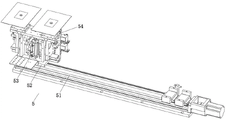
优选的,所述的移载平台包括移载直线模组、移载滑座、移载升降气缸及移载座,其中,上述移载直线模组水平设置于机台上;上述移载滑座设置在移载直线模组的输出端上,并经移载直线模组驱动而直线运动;上述移载升降气缸竖直设置在移载滑座上,且输出端朝上设置,移载升降气缸的输出端上连接有水平支板;上述移载座包括至少二个,移载座水平设置在水平支板上,移载座的表面布设有真空吸孔,以便吸附固定物料。Preferably, the transfer platform includes a transfer linear module, a transfer slide, a transfer lift cylinder and a transfer base, wherein the transfer linear module is horizontally arranged on the machine table; the transfer slide It is arranged on the output end of the transfer linear module, and is driven by the transfer linear module to move linearly; the above-mentioned transfer lift cylinder is vertically arranged on the transfer slide, and the output end is set upward, and the transfer lift cylinder A horizontal support plate is connected to the output end of the device; the above-mentioned transfer seat includes at least two, the transfer seat is horizontally arranged on the horizontal support plate, and the surface of the transfer seat is provided with vacuum suction holes to absorb fixed materials.
优选的,所述的上检测机构包括第三检测组件和第四检测组件,第三检测组件及第四检测组件沿物料直线移动方向间隔设置,在同一水平平面上两两一组形成四个检测点,检测点处形成圆形检测平面,移载平台带动片状物料在上检测机下方由左至右直线移动时,包括二次检测位置,其中第一次检测为物料右侧边角移动至第三检测组件的圆形检测平面中心位置处,第二次检测为物料左侧边角移动至第四检测组件的圆形检测平面中心位置。Preferably, the upper detection mechanism includes a third detection component and a fourth detection component, the third detection component and the fourth detection component are arranged at intervals along the linear moving direction of the material, and four detections are formed in pairs on the same horizontal plane. A circular detection plane is formed at the detection point. When the transfer platform drives the sheet material to move linearly from left to right under the upper detection machine, it includes the secondary detection position. The first detection is when the right corner of the material moves to At the center position of the circular detection plane of the third detection component, the second detection is that the left corner of the material moves to the center position of the circular detection plane of the fourth detection component.
优选的,所述的第三检测组件和第四检测组件分别包括检测支架、上检测直线模组、上检测支座、上检测CCD及上检测光源,其中,上述检测支架为U型架体结构,检测支架架设在移载平台上方;上述上检测直线模组设置在检测支架上,第三检测组件和第四检测组件的上检测直线模组间隔设置;上述上检测支座竖直连接在上检测直线模组的输出端上;上述上检测CCD竖直设置在上检测支座的侧壁上,且镜头朝下设置;上述上检测光源设置于上检测支座的下部,且上检测光源的中部开设有拍摄透孔,拍摄透孔对应设置于上检测CCD的下部。Preferably, the third detection component and the fourth detection component respectively include a detection bracket, an upper detection linear module, an upper detection support, an upper detection CCD and an upper detection light source, wherein the detection bracket is a U-shaped frame structure , the detection bracket is erected above the transfer platform; the above-mentioned upper detection linear module is arranged on the detection bracket, and the upper detection linear modules of the third detection component and the fourth detection component are arranged at intervals; the above-mentioned upper detection support is vertically connected to the upper On the output end of the detection linear module; the above-mentioned upper detection CCD is vertically arranged on the side wall of the upper detection support, and the lens is arranged downward; the above-mentioned upper detection light source is arranged on the lower part of the upper detection support, and the upper detection light source A photographing through hole is opened in the middle, and the photographing through hole is correspondingly arranged at the lower part of the upper detection CCD.
优选的,所述的下料机构包括下料传送带、下料搬臂及不良品传送辊,其中,上述下料传送带设置于移载平台的一侧,并水平延伸至机台外侧,与后续工站对接;上述不良品传送辊设置在下料传送带的侧部,并沿垂直于下料传送带方向水平延伸;上述下料搬臂架设在下料传送带与不良品传送辊上方,下料搬臂从移载平台上取出检测后的物料,将良品物料搬移至下料传送带上,将不良品物料搬移至不良品传送辊上。Preferably, the feeding mechanism includes a feeding conveyor belt, a feeding arm and a conveying roller for defective products, wherein the feeding conveyor belt is arranged on one side of the transfer platform and extends horizontally to the outside of the machine, and is connected with the subsequent work. Station docking; the above-mentioned defective product conveying roller is arranged on the side of the unloading conveyor belt and extends horizontally in the direction perpendicular to the unloading conveyor belt; the above-mentioned unloading conveying arm is erected above the unloading conveyor belt and the defective product conveying roller. The tested materials are taken out from the platform, the good materials are moved to the unloading conveyor belt, and the defective materials are moved to the defective conveying rollers.
优选的,所述的下料搬臂包括水平驱动组件、竖直驱动组件、旋转驱动组件及取料组件,其中,上述水平驱动组件架设在机台上;上述竖直驱动组件连接于水平驱动组件上,并经水平驱动组件驱动而在水平面内沿X轴方向及Y轴方向直线运动;上述旋转驱动组件连接在竖直驱动组件上,经竖直驱动组件驱动而沿竖直方向直线运动;上述取料组件连接在旋转驱动组件上,旋转驱动组件驱动取料组件在水平面内旋转运动,取料组件通过真空负压吸附物料。Preferably, the unloading arm includes a horizontal drive assembly, a vertical drive assembly, a rotary drive assembly and a reclaiming assembly, wherein the horizontal drive assembly is erected on the machine table; the vertical drive assembly is connected to the horizontal drive assembly The above-mentioned rotary drive assembly is connected to the vertical drive assembly, and is driven by the vertical drive assembly to move linearly in the vertical direction in the horizontal plane; The reclaiming component is connected to the rotating drive component, the rotating driving component drives the reclaiming component to rotate in the horizontal plane, and the reclaiming component absorbs the material through vacuum negative pressure.
优选的,所述的水平驱动组件包括横向直线模组、纵向直线模组及下料滑座,其中,上述横向直线模组沿横向方向架设在机台上,横向直线模组的一侧平行间隔第设置有下料支架,下料支架的顶部设有直线滑轨;上述纵向直线模组沿纵向方向设置在横向直线模组及下料支架上,经横向直线模组驱动而沿直线滑轨直线运动;上述下料滑座可活动地连接在纵向直线模组上,经纵向直线模组驱动沿纵向方向直线运动;上述竖直驱动组件包括竖向气缸及竖向滑座,其中,上述竖向气缸连接与于下料滑座的外侧壁上,且输出端朝下设置;上述竖向滑座沿竖直方向可滑动地连接在下料滑座上,且与竖向气缸的输出端连接;上述旋转驱动组件包括旋转电机,旋转电机连接在竖向滑座上,且输出端朝下设置;上述取料组件包括取料支座及取料吸嘴,其中,上述取料支座水平连接在旋转电机的输出端下部,旋转电机驱动取料支座在水平面内旋转运动,以便调整角度;取料支座上开设有条槽,条槽包括二个,分别平行间隔地设置在取料支座上;上述取料吸嘴包括至少二个,取料吸嘴可拆卸地安装在条槽内,通过条槽调整安装位置,且竖直延伸至条槽下方,通过底部的真空吸嘴吸附物料。Preferably, the horizontal drive assembly includes a transverse linear module, a longitudinal linear module and a blanking slide, wherein the transverse linear module is erected on the machine table along the transverse direction, and one side of the transverse linear module is spaced parallel to one another. The first is provided with a blanking bracket, and the top of the blanking bracket is provided with a linear sliding rail; the above-mentioned longitudinal linear module is arranged on the horizontal linear module and the blanking bracket along the longitudinal direction, and is driven by the transverse linear module to linearly move along the linear sliding rail. The above-mentioned blanking sliding seat is movably connected to the longitudinal linear module, and is driven by the longitudinal linear module to move linearly in the longitudinal direction; the above-mentioned vertical driving assembly includes a vertical cylinder and a vertical sliding seat, wherein the above-mentioned vertical The cylinder is connected to the outer side wall of the blanking slide, and the output end is set downward; the above-mentioned vertical slide is slidably connected to the blanking slide along the vertical direction, and is connected with the output end of the vertical cylinder; the above-mentioned The rotary drive assembly includes a rotary motor, the rotary motor is connected to the vertical sliding seat, and the output end is arranged downward; the above-mentioned material reclaiming assembly includes a material reclaiming support and a material reclaiming nozzle, wherein the above-mentioned reclaiming support is horizontally connected to the rotating At the lower part of the output end of the motor, the rotary motor drives the reclaiming support to rotate in the horizontal plane to adjust the angle; the reclaiming support is provided with a slot, and the slot includes two, which are arranged on the reclaiming support in parallel and spaced apart. The above-mentioned reclaiming nozzles include at least two, the reclaiming nozzles are detachably installed in the strip groove, the installation position is adjusted through the strip groove, and extends vertically to the bottom of the strip groove, and the vacuum suction nozzle at the bottom absorbs the material.
本实用新型的检测工艺,包括如下工艺步骤:The detection process of the utility model comprises the following process steps:
S1、上料:待检测的物料上料至上料平台上;S1. Loading: the material to be tested is loaded onto the loading platform;
S2、物料搬移:步骤S1中上料平台上的物料经上料搬臂吸取搬移;S2, material moving: in step S1, the material on the loading platform is sucked and moved by the loading arm;
S3、物料底面检测:步骤S2中上料搬臂从上料平台吸附物料后,带动物料在下检测机构的上方直线移动,经下检测机构拍摄检测物料底面;S3, material bottom surface detection: in step S2, after the loading arm absorbs the material from the loading platform, it drives the material to move linearly above the lower detection mechanism, and the bottom surface of the material is photographed and detected by the lower detection mechanism;
S4、物料顶面检测:步骤S3中底面检测完成后的物料经上料搬臂放置于移载平台上,移载平台带动物料在上检测机构下方直线移动,下检测机构对物料顶面进行拍摄检测;S4, material top surface detection: in step S3, the material after the bottom surface detection is completed is placed on the transfer platform by the loading arm, the transfer platform drives the material to move linearly under the upper detection mechanism, and the lower detection mechanism takes a picture of the top surface of the material detection;
S5、不良品下料:步骤S4中检测完成后的不良品经下料搬臂从移载平台取出后移送至不良品传送辊上,经不良品传送辊下料;S5, unloading of defective products: the defective products after the detection in step S4 are taken out from the transfer platform by the unloading arm and then transferred to the defective product conveying roller, and then unloaded by the defective product conveying roller;
S6、良品下料:步骤S4中检测完成后的良品物料经下料搬臂从移载平台取出后移送至下料传送带上,经下料传送带下料。S6, good product unloading: the good product material after the detection in step S4 is taken out from the transfer platform by the unloading arm, and then transferred to the unloading conveyor belt, and then unloaded by the unloading conveyor belt.
本实用新型的有益效果在于:The beneficial effects of the present utility model are:
本实用新型针对现有技术存在的缺陷和不足自主研发设计了一种以四个CCD镜头可拍摄的圆形检测面为四个检测基点,以检测基点的精度实现偏光片贴合正面贴合精度检测,且有效地覆盖了整个贴附面,且集成有上下两贴附面检测功能的贴片精度检测机。Aiming at the defects and deficiencies existing in the prior art, the utility model independently develops and designs a circular detection surface that can be photographed by four CCD lenses as four detection base points, and realizes the bonding precision of polarizers on the front surface with the accuracy of the detection base points. It can detect and effectively cover the entire attachment surface, and integrates the patch precision inspection machine with the detection function of the upper and lower attachment surfaces.
本实用新型针对偏光片贴附至玻璃基材后的检测工艺进行研究创新,独创性地采用四个检测CCD组成整体的检测执行部件,CCD两两一组,分别左右间隔设置,两组CCD之间的间距与待检测的物料的宽度一致,同时两组CCD之间的间距可进行实时调整,以便适应不同尺寸的屏幕贴片精度检测。通过四个布局于同一平面的CCD,将传统单个CCD的检测面扩展为以四个CCD为边角的矩形检测平面,同时位于边角处的单个CCD形成的圆形检测面;从而解决了实际检测过程中传统的CCD检测平面无法覆盖屏幕待检平面的情况。同时,上述CCD边角布局结构,有效地利用偏光片贴合过程中如果出现精度误差,即位置误差或角度误差出现时,会直接在矩形屏幕的四个边角处出现偏光片与屏幕不对齐的情况,因此仅仅通过检测四个边角位置的贴合情况即可推断整片偏光片的贴合精度情况,通过该种工艺创新无需检测平面完全覆盖待检测面;适应所有矩形屏幕的检测工艺。本实用新型的精度检测工艺,整体包括二次检测,以四个CCD形成的圆形检测面为基准,屏幕的右侧两边角分别移动至左侧两CCD圆形检测面的圆心处时进行第一次检测;屏幕的左侧两边角移动至右侧两CCD圆形检测面处时进行第二次检测;通过二次检测实现对屏幕四个边角位置表面完全检测。The utility model researches and innovates the detection process after the polarizer is attached to the glass substrate, and creatively adopts four detection CCDs to form an integral detection execution part. The distance between them is consistent with the width of the material to be detected, and the distance between the two sets of CCDs can be adjusted in real time to adapt to the precision detection of screen patches of different sizes. Through four CCDs arranged on the same plane, the detection surface of a traditional single CCD is expanded into a rectangular detection plane with four CCDs as corners, and a circular detection surface formed by a single CCD at the corners; During the inspection process, the traditional CCD inspection plane cannot cover the screen to be inspected. At the same time, the above-mentioned CCD edge and corner layout structure effectively utilizes the polarizer and screen misalignment at the four corners of the rectangular screen if there is an accuracy error during the bonding process of the polarizer, that is, when the position error or angle error occurs. Therefore, the bonding accuracy of the entire polarizer can be inferred only by detecting the bonding of the four corners. This process innovation does not require the testing plane to completely cover the surface to be tested; it is suitable for all rectangular screen testing processes . The precision detection process of the utility model includes secondary detection as a whole. Taking the circular detection surface formed by four CCDs as the benchmark, the second two corners of the screen are respectively moved to the center of the circular detection surfaces of the two CCDs on the left. One inspection; when the left two corners of the screen move to the two CCD circular inspection surfaces on the right, the second inspection is performed; through the second inspection, the surface of the four corners of the screen is completely inspected.
另外,本实用新型还集成有上表面检测功能和下表面检测功能,在实际生产过程中可同时适应不同检测面的工艺需求,具有良好的通用性。In addition, the utility model also integrates the upper surface detection function and the lower surface detection function, which can simultaneously adapt to the technological requirements of different detection surfaces in the actual production process, and has good versatility.
另外,本实用新型设计有下料搬臂用于将检测完成后的屏幕自动搬移至不良品传送辊或下料传送带上,本实用新型的下料搬臂包括水平驱动组件、竖直驱动组件及旋转驱动组件,通过水平驱动组件实现水平面内的横向及纵向方向直线驱动;通过竖直驱动组件实现竖直方向直线驱动,通过旋转驱动组件实现水平面内旋转驱动。通过以上各驱动组件使下料搬臂集成有四个方向的自由度调节,在实际取放料过程中可适应不同位置及角度的自动取放料要求,以便精准地对接上下工序之间物料位置差异情况;同时具备位置和角度实时调整校正功能,以便适应在实际工作过程中物料因搬运放置时出现的位置或角度偏差,有效保证取放料精度。另外,本实用新型的下料搬臂通过真空吸嘴底部的真空吸嘴产生的真空负压吸附物料,真空吸嘴可拆卸地安装在条槽内,拆卸后可沿条槽自由滑动,从而实现位置调整,以便适应不同尺寸取放时的真空吸附点位置不同要求。In addition, the utility model is designed with a blanking arm for automatically moving the screen after the detection is completed to the defective product conveying roller or the blanking conveyor belt. For the rotary drive assembly, the horizontal drive assembly realizes linear drive in the horizontal and longitudinal directions; the vertical drive assembly realizes the vertical linear drive, and the rotary drive assembly realizes the rotational drive in the horizontal plane. Through the above drive components, the unloading arm is integrated with four-direction freedom adjustment, which can adapt to the requirements of automatic picking and unloading of different positions and angles during the actual picking and unloading process, so as to accurately connect the material position between the upper and lower processes. At the same time, it has the function of real-time adjustment and correction of position and angle, so as to adapt to the position or angle deviation of materials due to handling and placement in the actual working process, and effectively ensure the accuracy of picking and placing materials. In addition, the unloading arm of the present invention absorbs materials through the vacuum negative pressure generated by the vacuum suction nozzle at the bottom of the vacuum suction nozzle. The vacuum suction nozzle is detachably installed in the groove, and can slide freely along the groove after disassembly, so as to realize The position is adjusted to meet the different requirements of the vacuum suction point position when picking and placing different sizes.
附图说明Description of drawings
图1为本实用新型的立体结构示意图之一。FIG. 1 is one of the three-dimensional structural schematic diagrams of the present invention.
图2为本实用新型的立体结构示意图之二。FIG. 2 is the second schematic diagram of the three-dimensional structure of the present invention.
图3为本实用新型的立体结构示意图之三。FIG. 3 is the third schematic diagram of the three-dimensional structure of the present invention.
图4为本实用新型的立体结构示意图之四。FIG. 4 is the fourth schematic diagram of the three-dimensional structure of the present invention.
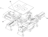
图5为本实用新型隐藏部件后的结构示意图之一。FIG. 5 is one of the structural schematic diagrams of the present invention after the hidden components.
图6为本实用新型隐藏部件后的结构示意图之二。FIG. 6 is the second structural schematic diagram of the utility model after the hidden components.
图7为本实用新型隐藏部件后的结构示意图之三。FIG. 7 is the third structural schematic diagram of the utility model after the hidden components.
图8为本实用新型隐藏部件后的结构示意图之四。FIG. 8 is the fourth schematic diagram of the structure of the present invention after the hidden components.
图9为本实用新型上料平台的立体结构示意图之一。FIG. 9 is one of the three-dimensional structural schematic diagrams of the feeding platform of the present invention.
图10为本实用新型上料平台的立体结构示意图之二。FIG. 10 is the second schematic diagram of the three-dimensional structure of the feeding platform of the present invention.
图11为本实用新型上料平台的立体结构示意图之三。11 is the third schematic diagram of the three-dimensional structure of the feeding platform of the present invention.
图12为本实用新型上料搬臂的立体结构示意图之一。FIG. 12 is one of the three-dimensional structural schematic diagrams of the feeding and moving arm of the present invention.
图13为本实用新型上料搬臂的立体结构示意图之二。FIG. 13 is the second schematic diagram of the three-dimensional structure of the feeding arm of the present invention.
图14为本实用新型下检测机构的立体结构示意图之一。FIG. 14 is one of the three-dimensional structural schematic diagrams of the lower detection mechanism of the present invention.
图15为本实用新型下检测机构的立体结构示意图之二。FIG. 15 is the second schematic diagram of the three-dimensional structure of the lower detection mechanism of the present invention.
图16为本实用新型下检测机构的立体结构示意图之三。FIG. 16 is the third schematic diagram of the three-dimensional structure of the lower detection mechanism of the present invention.
图17为本实用新型移载平台的立体结构示意图之一。FIG. 17 is one of the three-dimensional schematic diagrams of the transfer platform of the present invention.
图18为本实用新型移载平台的立体结构示意图之二。FIG. 18 is the second schematic diagram of the three-dimensional structure of the transfer platform of the present invention.
图19为本实用新型上检测机构的立体结构示意图之一。FIG. 19 is one of the three-dimensional schematic diagrams of the detection mechanism of the present invention.
图20为本实用新型上检测机构的立体结构示意图之二。FIG. 20 is the second schematic diagram of the three-dimensional structure of the detection mechanism of the present invention.
图21为本实用新型上检测机构的立体结构示意图之三。FIG. 21 is the third schematic diagram of the three-dimensional structure of the detection mechanism of the present invention.
图22为本实用新型下料传送带的立体结构示意图。Figure 22 is a schematic three-dimensional structure diagram of the blanking conveyor belt of the present invention.
图23为本实用新型贴片机构的立体结构示意图之三。FIG. 23 is the third schematic diagram of the three-dimensional structure of the patch mechanism of the present invention.
图24为本实用新型下料搬臂的立体结构示意图之一。FIG. 24 is one of the three-dimensional schematic diagrams of the blanking arm of the present invention.
图25为本实用新型下料搬臂的立体结构示意图之二。Figure 25 is the second schematic diagram of the three-dimensional structure of the blanking arm of the present invention.
图26为本实用新型检测工艺流程示意图。Figure 26 is a schematic diagram of the detection process flow of the present invention.
具体实施方式Detailed ways
下面将结合附图对本实用新型作进一步描述:The utility model will be further described below in conjunction with the accompanying drawings:
如图1至图26所示,本实用新型采取的技术方案如下:一种贴片精度检测机,包括上料平台2、上料搬臂3、下检测机构4、移载平台5、上检测机构6及下料机构,其中,上述上料平台2、下检测机构4及移载平台5沿直线方向间隔设置在机台1上;上述上检测机构6架设在移载平台5的上方;待检测的物料经上料平台2上料,上料搬臂3从上料平台2上搬取物料后从下检测机构4上方直线移动,经下检测机构4检测物料底部,并将物料放置在移载平台5上,移载平台5带动物料在上检测机构6下发直线移动,经上检测机构6对物料表面进行检测;上述下料机构设置在上检测机构6的侧部,检测后的物料经下料机构下料。As shown in Figures 1 to 26, the technical solutions adopted by the present invention are as follows: a patch precision detection machine, comprising a
上料平台2包括第一直线模组21、第二直线模组22及支台23,其中,上述第一直线模组21水平设置在机台1上;上述第二直线模组22沿垂直于第一直线模组21方向设置,并与第一直线模组21的输出端连接,第一直线模组21驱动第二直线模组22沿其设置方向直线移动;上述支台23包括至少二个,支台23间隔设置于第二直线模组22上,并与第二直线模组22的输出端连接,第二直线模组22驱动支台23沿垂直于第一直线模组21方向直线运动,支台23的顶部布设有真空吸孔,以便吸附固定物料。The
上料搬臂3包括搬臂直线模组31、搬臂滑座32及吸座33,其中,上述搬臂直线模组31架设在上料平台2的上方,并沿直线方向延伸至下检测机构4上方;上述搬臂滑座32连接与搬臂直线模组31的输出端上,经搬臂直线模组31驱动而直线运动;上述吸座33包括至少二个,吸座33连接于搬臂直线模组31的输出端上,吸座33底部布设有真空吸孔,以便从支台23上吸附物料后,带动片状物料在下检测机构4上方直线移动。The loading and moving
下检测机构4包括第一检测组件和第二检测组件,第一检测组件及第二检测组件沿物料直线移动方向间隔设置,在同一水平平面上两两一组形成四个检测点,检测点处形成圆形检测平面,上料搬臂3带动片状物料在检测机构4上方由左至右直线移动时,片状物料移动至第一检测组件两检测点圆心处时,包括二次检测位置,其中第一次检测为物料右侧边角移动至第一检测组件的圆形检测平面中心位置处;第二次检测为物料左侧边角移动至第二检测组件的圆形检测平面中心位置。The
第一检测组件及第二检测组件分别包括下检测直线模组41、下检测支座42、下检测CCD43及下检测光源44,其中,上述下检测直线模组41水平设置在机台1上,第一检测组件和第二检测组件的下检测直线模组41间隔设置;上述下检测支座42竖直连接在下检测直线模组的输出端上;上述下检测CCD43竖直设置在下检测支座42的侧壁上,且镜头朝上设置;上述下检测光源44设置于下检测支座42的顶部,且下检测光源44的中部开设有拍摄透孔,拍摄透孔对应设置于下检测CCD的上部。The first detection component and the second detection component respectively include a lower detection
移载平台5包括移载直线模组51、移载滑座52、移载升降气缸53及移载座54,其中,上述移载直线模组51水平设置于机台1上;上述移载滑座52设置在移载直线模组51的输出端上,并经移载直线模组51驱动而直线运动;上述移载升降气缸53竖直设置在移载滑座52上,且输出端朝上设置,移载升降气缸53的输出端上连接有水平支板;上述移载座54包括至少二个,移载座54水平设置在水平支板上,移载座54的表面布设有真空吸孔,以便吸附固定物料。The
上检测机构6包括第三检测组件和第四检测组件,第三检测组件及第四检测组件沿物料直线移动方向间隔设置,在同一水平平面上两两一组形成四个检测点,检测点处形成圆形检测平面,移载平台5带动片状物料在上检测机构6下方由左至右直线移动时,包括二次检测位置,其中第一次检测为物料右侧边角移动至第三检测组件的圆形检测平面中心位置处,第二次检测为物料左侧边角移动至第四检测组件的圆形检测平面中心位置。The
第三检测组件和第四检测组件分别包括检测支架、上检测直线模组61、上检测支座62、上检测CCD63及上检测光源64,其中,上述检测支架为U型架体结构,检测支架架设在移载平台上方;上述上检测直线模组61设置在检测支架上,第三检测组件和第四检测组件的上检测直线模组61间隔设置;上述上检测支座62竖直连接在上检测直线模组的输出端上;上述上检测CCD63竖直设置在上检测支座62的侧壁上,且镜头朝下设置;上述上检测光源64设置于上检测支座62的下部,且上检测光源64的中部开设有拍摄透孔,拍摄透孔对应设置于上检测CCD的下部。The third detection component and the fourth detection component respectively include a detection bracket, an upper detection
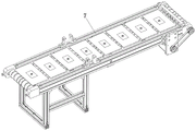
下料机构包括下料传送带7、下料搬臂8及不良品传送辊9,其中,上述下料传送带7设置于移载平台5的一侧,并水平延伸至机台1外侧,与后续工站对接;上述不良品传送辊9设置在下料传送带7的侧部,并沿垂直于下料传送带7方向水平延伸;上述下料搬臂8架设在下料传送带7与不良品传送辊9上方,下料搬臂8从移载平台5上取出检测后的物料,将良品物料搬移至下料传送带7上,将不良品物料搬移至不良品传送辊9上。The blanking mechanism includes a blanking
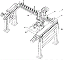
下料搬臂8包括水平驱动组件、竖直驱动组件、旋转驱动组件及取料组件,其中,上述水平驱动组件架设在机台1上;上述竖直驱动组件连接于水平驱动组件上,并经水平驱动组件驱动而在水平面内沿X轴方向及Y轴方向直线运动;上述旋转驱动组件连接在竖直驱动组件上,经竖直驱动组件驱动而沿竖直方向直线运动;上述取料组件连接在旋转驱动组件上,旋转驱动组件驱动取料组件在水平面内旋转运动,取料组件通过真空负压吸附物料。The
水平驱动组件包括横向直线模组81、纵向直线模组82及下料滑座83,其中,上述横向直线模组81沿横向方向架设在机台1上,横向直线模组81的一侧平行间隔第设置有下料支架,下料支架的顶部设有直线滑轨;上述纵向直线模组82沿纵向方向设置在横向直线模组81及下料支架上,经横向直线模组81驱动而沿直线滑轨直线运动;上述下料滑座83可活动地连接在纵向直线模组82上,经纵向直线模组82驱动沿纵向方向直线运动;上述竖直驱动组件包括竖向气缸84及竖向滑座85,其中,上述竖向气缸84连接与于下料滑座83的外侧壁上,且输出端朝下设置;上述竖向滑座85沿竖直方向可滑动地连接在下料滑座83上,且与竖向气缸84的输出端连接;上述旋转驱动组件包括旋转电机86,旋转电机86连接在竖向滑座85上,且输出端朝下设置;上述取料组件包括取料支座87及取料吸嘴88,其中,上述取料支座87水平连接在旋转电机86的输出端下部,旋转电机86驱动取料支座87在水平面内旋转运动,以便调整角度;取料支座87上开设有条槽,条槽包括二个,分别平行间隔地设置在取料支座87上;上述取料吸嘴88包括至少二个,取料吸嘴88可拆卸地安装在条槽内,通过条槽调整安装位置,且竖直延伸至条槽下方,通过底部的真空吸嘴吸附物料。The horizontal drive assembly includes a transverse
本实用新型的检测工艺,包括如下工艺步骤:The detection process of the utility model comprises the following process steps:
S1、上料:待检测的物料上料至上料平台上;S1. Loading: the material to be tested is loaded onto the loading platform;
S2、物料搬移:步骤S1中上料平台上的物料经上料搬臂吸取搬移;S2, material moving: in step S1, the material on the loading platform is sucked and moved by the loading arm;
S3、物料底面检测:步骤S2中上料搬臂从上料平台吸附物料后,带动物料在下检测机构的上方直线移动,经下检测机构拍摄检测物料底面;S3, material bottom surface detection: in step S2, after the loading arm absorbs the material from the loading platform, it drives the material to move linearly above the lower detection mechanism, and the bottom surface of the material is photographed and detected by the lower detection mechanism;
S4、物料顶面检测:步骤S3中底面检测完成后的物料经上料搬臂放置于移载平台上,移载平台带动物料在上检测机构下方直线移动,下检测机构对物料顶面进行拍摄检测;S4, material top surface detection: in step S3, the material after the bottom surface detection is completed is placed on the transfer platform by the loading arm, the transfer platform drives the material to move linearly under the upper detection mechanism, and the lower detection mechanism takes a picture of the top surface of the material detection;
S5、不良品下料:步骤S4中检测完成后的不良品经下料搬臂从移载平台取出后移送至不良品传送辊上,经不良品传送辊下料;S5, unloading of defective products: the defective products after the detection in step S4 are taken out from the transfer platform by the unloading arm and then transferred to the defective product conveying roller, and then unloaded by the defective product conveying roller;
S6、良品下料:步骤S4中检测完成后的良品物料经下料搬臂从移载平台取出后移送至下料传送带上,经下料传送带下料。S6, good product unloading: the good product material after the detection in step S4 is taken out from the transfer platform by the unloading arm, and then transferred to the unloading conveyor belt, and then unloaded by the unloading conveyor belt.
如图19至图21所示,为本发明上检测机构的示意图,上述图纸显示,本发明的上检测机构6中的上检测光源64为矩形体结构,该矩形体结构的上检测光源64向下发射光线至待检测位置后,由上检测CCD63拍摄检测位置实时照片后,传输至工控机进行分析处理判定表面状态。19 to 21 are schematic diagrams of the upper detection mechanism of the present invention. The above drawings show that the upper
作为一种替代的实施方案,上述上检测光源64还可以采用圆形体结构,其作用与上述矩形体结构的上检测光源64相同,也用于提供CCD检测时提供光线加强,区别在于光线照射区域或强度存在差异;同样可以满足CCD检测辅助光照的作用。As an alternative embodiment, the above-mentioned upper
进一步,本实用新型设计了一种以四个CCD镜头可拍摄的圆形检测面为四个检测基点,以检测基点的精度实现偏光片贴合正面贴合精度检测,且有效地覆盖了整个贴附面,且集成有上下两贴附面检测功能的贴片精度检测机。Further, the utility model designs a circular detection surface that can be photographed by four CCD lenses as four detection base points, and realizes the detection of the bonding accuracy of the polarizer sticking front with the accuracy of the detection base point, and effectively covers the entire sticker. Attachment, and integrated with the upper and lower attachment surface detection function of the patch precision inspection machine.
本实用新型针对偏光片贴附至玻璃基材后的检测工艺进行研究创新,独创性地采用四个检测CCD组成整体的检测执行部件,CCD两两一组,分别左右间隔设置,两组CCD之间的间距与待检测的物料的宽度一致,同时两组CCD之间的间距可进行实时调整,以便适应不同尺寸的屏幕贴片精度检测。通过四个布局于同一平面的CCD,将传统单个CCD的检测面扩展为以四个CCD为边角的矩形检测平面,同时位于边角处的单个CCD形成的圆形检测面;从而解决了实际检测过程中传统的CCD检测平面无法覆盖屏幕待检平面的情况。同时,上述CCD边角布局结构,有效地利用偏光片贴合过程中如果出现精度误差,即位置误差或角度误差出现时,会直接在矩形屏幕的四个边角处出现偏光片与屏幕不对齐的情况,因此仅仅通过检测四个边角位置的贴合情况即可推断整片偏光片的贴合精度情况,通过该种工艺创新无需检测平面完全覆盖待检测面;适应所有矩形屏幕的检测工艺。本实用新型的精度检测工艺,整体包括二次检测,以四个CCD形成的圆形检测面为基准,屏幕的右侧两边角分别移动至左侧两CCD圆形检测面的圆心处时进行第一次检测;屏幕的左侧两边角移动至右侧两CCD圆形检测面处时进行第二次检测;通过二次检测实现对屏幕四个边角位置表面完全检测。The utility model researches and innovates the detection process after the polarizer is attached to the glass substrate, and creatively adopts four detection CCDs to form an integral detection execution part. The distance between them is consistent with the width of the material to be detected, and the distance between the two sets of CCDs can be adjusted in real time to adapt to the precision detection of screen patches of different sizes. Through four CCDs arranged on the same plane, the detection surface of a traditional single CCD is expanded into a rectangular detection plane with four CCDs as corners, and a circular detection surface formed by a single CCD at the corners; During the inspection process, the traditional CCD inspection plane cannot cover the screen to be inspected. At the same time, the above-mentioned CCD edge and corner layout structure effectively utilizes the polarizer and screen misalignment at the four corners of the rectangular screen if there is an accuracy error during the bonding process of the polarizer, that is, when the position error or angle error occurs. Therefore, the bonding accuracy of the entire polarizer can be inferred only by detecting the bonding of the four corners. This process innovation does not require the testing plane to completely cover the surface to be tested; it is suitable for all rectangular screen testing processes . The precision detection process of the utility model includes secondary detection as a whole. Taking the circular detection surface formed by four CCDs as the benchmark, the second two corners of the screen are respectively moved to the center of the circular detection surfaces of the two CCDs on the left. One inspection; when the left two corners of the screen move to the two CCD circular inspection surfaces on the right, the second inspection is performed; through the second inspection, the surface of the four corners of the screen is completely inspected.
另外,本实用新型还集成有上表面检测功能和下表面检测功能,在实际生产过程中可同时适应不同检测面的工艺需求,具有良好的通用性。In addition, the utility model also integrates the upper surface detection function and the lower surface detection function, which can simultaneously adapt to the technological requirements of different detection surfaces in the actual production process, and has good versatility.
另外,本实用新型设计有下料搬臂用于将检测完成后的屏幕自动搬移至不良品传送辊或下料传送带上,本实用新型的下料搬臂包括水平驱动组件、竖直驱动组件及旋转驱动组件,通过水平驱动组件实现水平面内的横向及纵向方向直线驱动;通过竖直驱动组件实现竖直方向直线驱动,通过旋转驱动组件实现水平面内旋转驱动。通过以上各驱动组件使下料搬臂集成有四个方向的自由度调节,在实际取放料过程中可适应不同位置及角度的自动取放料要求,以便精准地对接上下工序之间物料位置差异情况;同时具备位置和角度实时调整校正功能,以便适应在实际工作过程中物料因搬运放置时出现的位置或角度偏差,有效保证取放料精度。另外,本实用新型的下料搬臂通过真空吸嘴底部的真空吸嘴产生的真空负压吸附物料,真空吸嘴可拆卸地安装在条槽内,拆卸后可沿条槽自由滑动,从而实现位置调整,以便适应不同尺寸取放时的真空吸附点位置不同要求。In addition, the utility model is designed with a blanking arm for automatically moving the screen after the detection is completed to the defective product conveying roller or the blanking conveyor belt. For the rotary drive assembly, the horizontal drive assembly realizes linear drive in the horizontal and longitudinal directions; the vertical drive assembly realizes the vertical linear drive, and the rotary drive assembly realizes the rotational drive in the horizontal plane. Through the above drive components, the unloading arm is integrated with four-direction freedom adjustment, which can adapt to the requirements of automatic picking and unloading of different positions and angles during the actual picking and unloading process, so as to accurately connect the material position between the upper and lower processes. At the same time, it has the function of real-time adjustment and correction of position and angle, so as to adapt to the position or angle deviation of materials due to handling and placement in the actual working process, and effectively ensure the accuracy of picking and placing materials. In addition, the unloading arm of the present invention absorbs materials through the vacuum negative pressure generated by the vacuum suction nozzle at the bottom of the vacuum suction nozzle. The vacuum suction nozzle is detachably installed in the groove, and can slide freely along the groove after disassembly, so as to realize The position is adjusted to meet the different requirements of the vacuum suction point position when picking and placing different sizes.
本实用新型的实施例只是介绍其具体实施方式,不在于限制其保护范围。本行业的技术人员在本实施例的启发下可以作出某些修改,故凡依照本实用新型专利范围所做的等效变化或修饰,均属于本实用新型专利权利要求范围内。The embodiments of the present utility model only describe the specific implementations thereof, and are not intended to limit the protection scope thereof. Those skilled in the art can make some modifications under the inspiration of this embodiment, so all equivalent changes or modifications made in accordance with the scope of the patent of the present invention belong to the scope of the claims of the patent of the present invention.
Claims (11)
Priority Applications (1)
| Application Number | Priority Date | Filing Date | Title |
|---|---|---|---|
| CN202122937118.5U CN216631663U (en) | 2021-11-27 | 2021-11-27 | Paster precision detection machine |
Applications Claiming Priority (1)
| Application Number | Priority Date | Filing Date | Title |
|---|---|---|---|
| CN202122937118.5U CN216631663U (en) | 2021-11-27 | 2021-11-27 | Paster precision detection machine |
Publications (1)
| Publication Number | Publication Date |
|---|---|
| CN216631663U true CN216631663U (en) | 2022-05-31 |
Family
ID=81737745
Family Applications (1)
| Application Number | Title | Priority Date | Filing Date |
|---|---|---|---|
| CN202122937118.5U Withdrawn - After Issue CN216631663U (en) | 2021-11-27 | 2021-11-27 | Paster precision detection machine |
Country Status (1)
| Country | Link |
|---|---|
| CN (1) | CN216631663U (en) |
Cited By (4)
| Publication number | Priority date | Publication date | Assignee | Title |
|---|---|---|---|---|
| CN114345735A (en) * | 2021-11-27 | 2022-04-15 | 深圳市易天自动化设备股份有限公司 | A patch precision testing machine and its testing process |
| CN115007501A (en) * | 2022-07-22 | 2022-09-06 | 深圳宝创电子设备有限公司 | High-precision chip, optical filter sorting method and sorting machine |
| CN116643107A (en) * | 2023-06-13 | 2023-08-25 | 和创联合科技(北京)有限公司 | A precision positioning test fixture for patch devices |
| CN118529490A (en) * | 2024-07-26 | 2024-08-23 | 厦门普诚半导体科技有限公司 | A loading and unloading detection device |
-
2021
- 2021-11-27 CN CN202122937118.5U patent/CN216631663U/en not_active Withdrawn - After Issue
Cited By (5)
| Publication number | Priority date | Publication date | Assignee | Title |
|---|---|---|---|---|
| CN114345735A (en) * | 2021-11-27 | 2022-04-15 | 深圳市易天自动化设备股份有限公司 | A patch precision testing machine and its testing process |
| CN114345735B (en) * | 2021-11-27 | 2025-09-12 | 深圳市易天自动化设备股份有限公司 | A patch precision detection machine and its detection process |
| CN115007501A (en) * | 2022-07-22 | 2022-09-06 | 深圳宝创电子设备有限公司 | High-precision chip, optical filter sorting method and sorting machine |
| CN116643107A (en) * | 2023-06-13 | 2023-08-25 | 和创联合科技(北京)有限公司 | A precision positioning test fixture for patch devices |
| CN118529490A (en) * | 2024-07-26 | 2024-08-23 | 厦门普诚半导体科技有限公司 | A loading and unloading detection device |
Similar Documents
| Publication | Publication Date | Title |
|---|---|---|
| CN216631663U (en) | Paster precision detection machine | |
| CN114345735A (en) | A patch precision testing machine and its testing process | |
| CN209460275U (en) | Mobile phone screen module testing equipment | |
| WO2022126878A1 (en) | Crack detection device for curved screen | |
| KR101264849B1 (en) | Producing apparatus for backlight unit | |
| CN210108988U (en) | AOI automatic screen defect detection production line | |
| CN113001166A (en) | Notebook computer touch pad alignment lock screw equipment | |
| CN116553174A (en) | Board adsorption mechanism and flexible circuit board preloading system using it | |
| CN118712112B (en) | A wafer NOTCH positioning and edge detection device | |
| CN111085464B (en) | Device for online detection of appearance of glass cover plate | |
| TWI623738B (en) | Vacuum suction device and material detecting device and material moving device thereof | |
| CN113414122B (en) | Flexible screen double-sided 3D inspection equipment | |
| CN106057697A (en) | Cell slice detection and positioning device | |
| CN209911252U (en) | Appearance testing equipment | |
| CN216638116U (en) | Automatic moving and correcting mechanism | |
| CN217237794U (en) | Diversified outward appearance detection device | |
| TWI574002B (en) | Vacuum suction device capable of adjusting adsorption area, material chip detecting device and material moving device | |
| CN212600118U (en) | A laptop touchpad alignment lock screw device | |
| CN217361027U (en) | Full-automatic high-speed laminating machine | |
| CN215986793U (en) | Detection device | |
| CN212069569U (en) | Glass apron outward appearance on-line measuring device | |
| CN114093269A (en) | A fully automatic high-speed laminating machine and its laminating process | |
| CN223065130U (en) | Soft packet of battery outward appearance detection device | |
| CN216646308U (en) | Sectional independent precision detection mechanism | |
| CN220568667U (en) | Automatic product detection equipment |
Legal Events
| Date | Code | Title | Description |
|---|---|---|---|
| GR01 | Patent grant | ||
| GR01 | Patent grant | ||
| AV01 | Patent right actively abandoned | ||
| AV01 | Patent right actively abandoned | ||
| AV01 | Patent right actively abandoned |
Granted publication date: 20220531 Effective date of abandoning: 20250912 |
|
| AV01 | Patent right actively abandoned |
Granted publication date: 20220531 Effective date of abandoning: 20250912 |