CN214708446U - Integrated liquid cooling radiator - Google Patents
Integrated liquid cooling radiator Download PDFInfo
- Publication number
- CN214708446U CN214708446U CN202120628022.8U CN202120628022U CN214708446U CN 214708446 U CN214708446 U CN 214708446U CN 202120628022 U CN202120628022 U CN 202120628022U CN 214708446 U CN214708446 U CN 214708446U
- Authority
- CN
- China
- Prior art keywords
- liquid
- cavity
- collecting tank
- box body
- integrated
- Prior art date
- Legal status (The legal status is an assumption and is not a legal conclusion. Google has not performed a legal analysis and makes no representation as to the accuracy of the status listed.)
- Active
Links
Images


Landscapes
- Cooling Or The Like Of Electrical Apparatus (AREA)
Abstract
The utility model discloses an integrated liquid cooling radiator, which comprises a first liquid collecting tank, a second liquid collecting tank and a plurality of calandria; the first liquid collecting groove is made of heat dissipation metal materials, a first shunting liquid separating plate is arranged in the first liquid collecting groove, and the interior of the first liquid collecting groove is separated to form a first liquid inlet cavity and a first liquid outlet cavity; and the bottom of first collecting tank is provided with the heat conduction copper sheet, through setting up the heat conduction copper sheet on first collecting tank, in order to form the integral type structure, make this product compact structure, it is more convenient to use, and through be provided with the liquid pump in the second collecting tank, make the liquid pump form an organic whole with the collecting tank, the coolant liquid is effectively accelerated at the flow speed of calandria, the radiating efficiency is improved, and the cooperation all is provided with the reposition of redundant personnel at each collecting tank and separates the liquid board, the stroke that the coolant liquid flows has been prolonged greatly, make the coolant liquid can effectively fully cool down the heat dissipation, the whole radiating effect of product is very good.
Description
Technical Field
The utility model belongs to the technical field of the radiator technique and specifically relates to indicate an integral type liquid cooling radiator.
Background
The water-cooled radiator is driven by a pump to forcibly circulate liquid to take away heat of the radiator, and has the advantages of quiet, stable cooling, small dependence on the environment and the like compared with air cooling. The heat dissipation performance of a water-cooled heat sink is proportional to the flow rate of the cooling fluid (water or other liquid) therein, which in turn is related to the power of the water pump of the refrigeration system. And the heat capacity of water is large, so that the water-cooling refrigerating system has good heat load capacity.
The existing water-cooled radiator generally comprises a water-cooled radiator, a water-cooled head and a water pipe, wherein the water pipe is connected between the water-cooled radiator and the water-cooled head, the water pipe is used for enabling water in the water-cooled radiator and the water-cooled head to circularly flow, the water enters the water-cooled radiator for heat dissipation after absorbing heat on the water-cooled head, and the water after heat dissipation flows back to the water-cooled head. The water-cooling radiator water-cooling row and the water-cooling head are separately arranged, the structure is not compact, the use is inconvenient, the water collecting tank of the water-cooling row is not provided with a water pump function, the flowing speed of water in the water-cooling row is low, the heat dissipation efficiency is low, the water collecting tank is not divided, the flowing stroke of water in the water-cooling row is short, and the water can not be effectively cooled and dissipated. Therefore, there is a need to develop a solution to solve the above problems.
SUMMERY OF THE UTILITY MODEL
In view of this, the present invention provides an integrated liquid cooling radiator, which can effectively solve the problems of compact structure, inconvenient use, low heat dissipation efficiency and incapability of effectively cooling and dissipating heat of the cooling liquid in the existing liquid cooling radiator.
In order to achieve the above purpose, the utility model adopts the following technical scheme:
an integrated liquid cooling radiator comprises a first liquid collecting tank, a second liquid collecting tank and a plurality of calandria; the two ends of the calandria are respectively communicated with the first liquid collecting tank and the second liquid collecting tank, the calandria are provided with heat radiating fins,
the first liquid collecting tank is made of heat-dissipating metal materials, a first shunting liquid separating plate is arranged in the first liquid collecting tank to separate the interior of the first liquid collecting tank into a first liquid inlet cavity and a first liquid outlet cavity, and the bottom of the first liquid collecting tank is provided with a first liquid inlet communicated with the first liquid inlet cavity and a first liquid outlet communicated with the first liquid outlet cavity; the bottom of the first liquid collecting groove is provided with a heat-conducting copper sheet, the liquid inlet end of the heat-conducting copper sheet is communicated with the first liquid inlet, and the liquid outlet end of the heat-conducting copper sheet is communicated with the first liquid outlet;
the second liquid collecting groove is made of heat-dissipating metal materials, a second flow-dividing liquid-separating plate is arranged in the second liquid collecting groove to separate the interior of the second liquid collecting groove into a second liquid inlet cavity and a second liquid outlet cavity, a liquid pump cavity is arranged in the second liquid inlet cavity, a second liquid inlet communicated with the second liquid inlet cavity and a second liquid outlet communicated with the second liquid outlet cavity are formed in the liquid pump cavity, and a liquid pump is arranged in the liquid pump cavity;
one part of the calandria is communicated between the first liquid outlet chamber and the second liquid inlet chamber, and the other part of the calandria is communicated between the first liquid inlet chamber and the second liquid outlet chamber.
As a preferable scheme, the first liquid collecting tank comprises a first box body and a first box cover; the first flow dividing and liquid separating plate is formed in the first box body, and the first liquid inlet and the first liquid outlet are formed in the bottom of the first box body; this first lid and the sealed fixed mounting of first box body, seted up a plurality of first mounting grooves on this first lid, the first feed liquor cavity of partly first mounting groove intercommunication, the first play liquid cavity of the first mounting groove intercommunication of another part, the corresponding tip of these a plurality of calandrias is sealed respectively and installs in the first mounting groove that corresponds.
As a preferred scheme, the heat conducting copper sheet is fixed on the bottom of the first box body through a fixing seat, a first sealing washer is clamped between the periphery of the inner side face of the fixing seat and the first box body, the heat conducting copper sheet is fixed on the bottom of the fixing seat, a second sealing washer is clamped between the periphery of the inner side face of the heat conducting copper sheet and the fixing seat, a liquid inlet and outlet liquid isolating rubber sheet covers the fin on the inner side face of the heat conducting copper sheet, the liquid inlet and outlet liquid isolating rubber sheet is clamped between the fixing seat and the heat conducting copper sheet, a slotted hole is formed in the liquid inlet and outlet liquid isolating rubber sheet, and the slotted hole is in right-way communication with the first liquid inlet.
As a preferred scheme, first box body and first lid are copper or aluminium material, and first lid is fixed through welding and first box body seal installation, and this first reposition of redundant personnel sepage board sets up in first box body through welding or integrated into one piece's mode.
As a preferable scheme, the second liquid collecting tank comprises a second box body, a second box cover and a liquid pump cover; the second flow-dividing liquid-separating plate is formed in the second box body; the second box cover and the second box body are fixedly installed in a sealing mode, a plurality of second installation grooves are formed in the second box cover, one part of the second installation grooves are communicated with the second liquid inlet cavity, the other part of the second installation grooves are communicated with the second liquid outlet cavity, and the corresponding end portions of the plurality of discharge pipes are installed in the corresponding second installation grooves in a sealing mode respectively; the liquid pump cover is fixed with the second box body and seals the opening of the liquid pump cavity in a sealing mode, the liquid pump is fixed on the inner side of the liquid pump cover, an impeller is fixed on an output shaft of the liquid pump, and the impeller is located in the liquid pump cavity and driven by the liquid pump to rotate.
As a preferred scheme, a boss is convexly formed in the second liquid inlet cavity in an integrated manner, the liquid pump cavity is integrally formed and located on the back face of the boss, and the second liquid inlet is formed in the boss.
As a preferred scheme, second box body and second lid are copper or aluminium material, and the second lid is fixed through welding and second box body seal installation, and this second reposition of redundant personnel flow-isolating plate sets up in the second box body through welding or integrated into one piece's mode.
Preferably, the inner side of the liquid pump cover is convexly provided with a convex part, the convex part is matched with the liquid pump cavity, the convex part is embedded into the liquid pump cavity, the surface of the convex part is concavely provided with a concave position, and the liquid pump is embedded into the concave position for fixing.
As a preferred scheme, two fan fixing frames are connected in front of the first liquid collecting tank and the second liquid collecting tank, the two fan fixing frames are arranged on the left and right, and the plurality of discharge pipes are located between the two fan fixing frames.
Preferably, the rows of tubes are arranged in a row to form a single group of liquid rows or two rows arranged in front of and behind the row to form a double group of liquid rows.
Compared with the prior art, the utility model obvious advantage and beneficial effect have, particularly, can know by above-mentioned technical scheme:
through setting up the heat conduction copper sheet on first collecting tank, with the formation integral type structure, make this product compact structure, it is more convenient to use, and through be provided with the liquid pump in the second collecting tank, make the liquid pump form an organic whole with the collecting tank, the coolant liquid is effectively accelerated at the flow rate of calandria, the radiating efficiency has been improved, and the cooperation all is provided with the reposition of redundant personnel flow spacer in each collecting tank, the stroke that the coolant liquid flows has been prolonged greatly, make the coolant liquid can effectively fully cool down the heat dissipation, the whole radiating effect of product is very good.
To illustrate the structural features and functions of the present invention more clearly, the present invention will be described in detail with reference to the accompanying drawings and specific embodiments.
Drawings
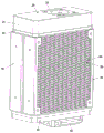
FIG. 1 is an assembled perspective view of a first preferred embodiment of the present invention;
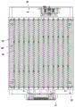
FIG. 2 is a front view of a first preferred embodiment of the present invention;
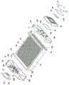
fig. 3 is an exploded view of a first preferred embodiment of the present invention;
FIG. 4 is a front view of a first sump in a first preferred embodiment of the invention;
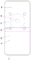
FIG. 5 is a front view of a second sump in accordance with a first preferred embodiment of the present invention;
FIG. 6 is an assembled perspective view of a second preferred embodiment of the present invention;
FIG. 7 is a front view of a second preferred embodiment of the present invention;
fig. 8 is an exploded view of a second preferred embodiment of the present invention;
FIG. 9 is a front view of a first sump in a second preferred embodiment of the invention;
fig. 10 is a front view of a second sump in a second preferred embodiment of the invention.
The attached drawings indicate the following:
10. first liquid collecting tank 11 and first box body
12. First box cover 101 and first flow-dividing liquid-separating plate
102. First liquid inlet chamber 103 and first liquid outlet chamber
104. A first liquid inlet 105 and a first liquid outlet
106. First mounting groove 20 and second liquid collecting groove
21. Second case 211, boss
22. Second box cover 23 and liquid pump cover
231. Convex part 201 and second flow-dividing liquid-separating plate
202. The second liquid inlet chamber 203 and the second liquid outlet chamber
204. Liquid pump cavity 205 and second liquid inlet
206. Second liquid outlet 207 and second mounting groove
208. Concave position 30, calandria
41. Heat conduction copper sheet 411 and fin
42. Fixing seat 43 and first sealing washer
44. Second sealing washer 45, liquid inlet and outlet liquid-proof rubber sheet
451. Slotted hole 51 and liquid pump
52. Impeller 60 and heat radiating fins
70. A fan fixing frame.
Detailed Description
Referring to fig. 1 to 5, the detailed structure of the first preferred embodiment of the present invention is shown, which includes a first liquid collecting tank 10, a second liquid collecting tank 20 and a plurality of calandria 30.
The first liquid collecting tank 10 is made of heat-dissipating metal, a first shunting liquid-separating plate 101 is arranged in the first liquid collecting tank 10 to separate the interior of the first liquid collecting tank 10 into a first liquid inlet cavity 102 and a first liquid outlet cavity 103, and the bottom of the first liquid collecting tank 10 is provided with a first liquid inlet 104 communicated with the first liquid inlet cavity 102 and a first liquid outlet 105 communicated with the first liquid outlet cavity 103; and the bottom of the first liquid collecting tank 10 is provided with a heat conducting copper sheet 41, the liquid inlet end of the heat conducting copper sheet 41 is communicated with the first liquid inlet 104, and the liquid outlet end of the heat conducting copper sheet 41 is communicated with the first liquid outlet 105.
Specifically, the first sump 10 includes a first box 11 and a first box cover 12; the first flow dividing and liquid separating plate 101 is formed in the first box body 11, and the first liquid inlet 104 and the first liquid outlet 105 are formed in the bottom of the first box body 11; this first lid 12 and the sealed fixed mounting of first box body 11, seted up a plurality of first mounting grooves 106 on this first lid 12, the first feed liquor cavity 102 of a part first mounting groove 106 intercommunication, the first play liquid cavity 103 of the first mounting groove 106 intercommunication of another part, and, first box body 11 and first lid 12 are copper or aluminium material, and first lid 12 is fixed through welding and the sealed mounting of first box body 11, and this first reposition of redundant personnel partition plate 101 sets up in first box body 11 through welding or integrated into one piece's mode.
The heat conducting copper sheet 41 is fixed on the bottom of the first box body 11 through a fixing seat 42, a first sealing washer 43 is clamped between the periphery of the inner side face of the fixing seat 42 and the first box body 11, the heat conducting copper sheet 41 is fixed on the bottom of the fixing seat 42, a second sealing washer 44 is clamped between the periphery of the inner side face of the heat conducting copper sheet 41 and the fixing seat 42, a liquid inlet and outlet liquid-proof rubber sheet 45 covers fins 411 on the inner side face of the heat conducting copper sheet 41, the liquid inlet and outlet liquid-proof rubber sheet 45 is clamped between the fixing seat 42 and the heat conducting copper sheet 41, a slotted hole 451 is formed in the liquid inlet and outlet liquid-proof rubber sheet 45, and the slotted hole 451 is in direct communication with the first liquid inlet 104.
This second collecting tank 20 is the heat dissipation metal material, is provided with second branch flow partition plate 201 in the second collecting tank 20 and separates the inside of second collecting tank 20 and be formed with second feed liquor cavity 202 and second play liquid cavity 203, is provided with liquid pump cavity 204 in this second feed liquor cavity 202, sets up the second inlet 205 of intercommunication second feed liquor cavity 202 and the second liquid outlet 206 of intercommunication second play liquid cavity 203 on this liquid pump cavity 204, and is provided with liquid pump 51 in the liquid pump cavity 204.
Specifically, the second liquid collecting tank 20 includes a second box body 21, a second box cover 22 and a liquid pump cover 23; the second flow-dividing liquid-separating plate 201 is formed in the second box body 21; the second box cover 22 and the second box body 21 are fixedly installed in a sealing manner, a plurality of second installation grooves 207 are formed in the second box cover 22, one part of the second installation grooves 207 are communicated with the second liquid inlet chamber 202, and the other part of the second installation grooves 207 are communicated with the second liquid outlet chamber 203; the liquid pump cover 23 is fixed to the second box 21 and covers the opening of the liquid pump chamber 204, the liquid pump 51 is fixed to the inner side of the liquid pump cover 23, an impeller 52 is fixed to an output shaft of the liquid pump 51, and the impeller 52 is located in the liquid pump chamber 204 and is driven by the liquid pump 51 to rotate. In this embodiment, the second box body 21 and the second cover 22 are both made of copper or aluminum, the second box cover 22 is fixed to the second box body 21 by welding, and the second flow-dividing liquid-separating plate 201 is disposed in the second box body 21 by welding or integrally forming; the second liquid inlet chamber 202 is provided with a boss 211 in an integrally formed and protruding manner, the liquid pump chamber 204 is provided in an integrally formed and located on the back of the boss 211, the second liquid inlet 205 is opened on the boss 211, the inner side of the liquid pump cover 23 is provided with a protruding portion 231 in a protruding manner, the protruding portion 231 is matched with the liquid pump chamber 204, the protruding portion 231 is embedded into the liquid pump chamber 204, the surface of the protruding portion 231 is provided with a concave portion 208 in a concave manner, and the liquid pump 51 is embedded into the concave portion 208 and fixed.
The two ends of the plurality of calandria 30 are respectively communicated with the first header tank 10 and the second header tank 20, the plurality of calandria 30 are provided with the heat dissipation fins 60, specifically, a part of the calandria 30 is communicated between the first liquid outlet chamber 103 and the second liquid inlet chamber 202, and the other part of the calandria 30 is communicated between the first liquid inlet chamber 102 and the second liquid outlet chamber 203. In the present embodiment, the corresponding ends of the plurality of rows of tubes 30 are respectively and hermetically mounted in the corresponding first mounting grooves 106, and the corresponding ends of the plurality of rows of tubes 30 are respectively and hermetically mounted in the corresponding second mounting grooves 207; and, the rows of tubes 30 are arranged in a row to form a single set of rows of liquid; in addition, two fan fixing brackets 70 are connected in front of the first liquid collecting tank 10 and the second liquid collecting tank 20, the two fan fixing brackets 70 are arranged on the left and right, the plurality of discharge pipes 30 are located between the two fan fixing brackets 70, and the two fan fixing brackets 70 are used for installing and fixing a heat dissipation fan so as to accelerate heat dissipation efficiency.
Detailed description the working principle of the present embodiment is as follows:
when the cooling device is used, the heating device is fixedly attached to the heat-conducting copper sheet 41, the two fan fixing frames 70 are provided with the heat-radiating fans, heat generated by the heating device during operation is conducted to the heat-conducting copper sheet 41, at the moment, the liquid pump 51 and the heat-radiating fans can be turned on to absorb heat and cool the heat-conducting copper sheet 41, specifically, after the liquid pump 51 is turned on, cooling liquid (such as water and the like) in the cooling device starts to circulate in a flow channel, the cooling liquid with lower temperature enters the heat-conducting copper sheet 41 from the first liquid inlet cavity 102 through the first liquid inlet 104, the cooling liquid flows through the fins 411 on the heat-conducting copper sheet 41 to absorb the heat on the heat-conducting copper sheet 41, at the moment, the temperature of the cooling liquid rises after absorbing the heat and enters the first liquid outlet cavity 103 from the first liquid outlet 105, then the cooling liquid is divided into multiple paths and flows into the second liquid inlet cavity 202 from a part of the discharge pipes 30, and the cooling liquid absorbs a part of heat when flowing through the discharge pipes 30 for the first time, the heat on the discharging pipe 30 is absorbed by the heat-dissipating fan in time; then, the cooling liquid enters the liquid pump chamber 204 through the second liquid inlet 205, in the liquid pump chamber 204, the cooling liquid enters the second liquid outlet chamber 203 through the second liquid outlet 206 after being pressurized, then the cooling liquid is divided into multiple paths and flows back to the first liquid inlet chamber 102 from the other part of the exhaust pipe 30, the cooling liquid absorbs heat again when flowing through the exhaust pipe 30 for the second time, so that the temperature of the cooling liquid is further reduced, the cooled cooling liquid enters the heat-conducting copper sheet 41 again through the first liquid inlet 104 to absorb heat, and the circulation is repeated in this way, so that the heat on the heat-conducting copper sheet 41 is continuously absorbed, the normal operation of the heating device is ensured, and no abnormality is caused by overhigh temperature.
Referring to fig. 6 to 10, a specific structure of a second preferred embodiment of the present invention is shown, which is basically the same as the specific structure of the first preferred embodiment, except that:
in this embodiment, the rack pipes 30 are arranged in two rows arranged in front of and behind to form a double-liquid-bank, so that the cooling liquid capacity of the product is larger, more heat can be absorbed, the heat dissipation effect is better, and the use requirement of a high-power heating device with large heat productivity can be better met.
The utility model discloses a design focus lies in: through setting up the heat conduction copper sheet on first collecting tank, with the formation integral type structure, make this product compact structure, it is more convenient to use, and through be provided with the liquid pump in the second collecting tank, make the liquid pump form an organic whole with the collecting tank, the coolant liquid is effectively accelerated at the flow rate of calandria, the radiating efficiency has been improved, and the cooperation all is provided with the reposition of redundant personnel flow spacer in each collecting tank, the stroke that the coolant liquid flows has been prolonged greatly, make the coolant liquid can effectively fully cool down the heat dissipation, the whole radiating effect of product is very good.
The above description is only a preferred embodiment of the present invention, and is not intended to limit the technical scope of the present invention, so that any slight modifications, equivalent changes and modifications made by the technical spirit of the present invention to the above embodiments are all within the scope of the technical solution of the present invention.
Claims (10)
1. An integrated liquid cooling radiator comprises a first liquid collecting tank, a second liquid collecting tank and a plurality of calandria; the both ends of these a plurality of calandrias communicate with first collecting tank and second collecting tank respectively, are provided with heat radiation fins on these a plurality of calandrias, its characterized in that:
the first liquid collecting tank is made of heat-dissipating metal materials, a first shunting liquid separating plate is arranged in the first liquid collecting tank to separate the interior of the first liquid collecting tank into a first liquid inlet cavity and a first liquid outlet cavity, and the bottom of the first liquid collecting tank is provided with a first liquid inlet communicated with the first liquid inlet cavity and a first liquid outlet communicated with the first liquid outlet cavity; the bottom of the first liquid collecting groove is provided with a heat-conducting copper sheet, the liquid inlet end of the heat-conducting copper sheet is communicated with the first liquid inlet, and the liquid outlet end of the heat-conducting copper sheet is communicated with the first liquid outlet;
the second liquid collecting groove is made of heat-dissipating metal materials, a second flow-dividing liquid-separating plate is arranged in the second liquid collecting groove to separate the interior of the second liquid collecting groove into a second liquid inlet cavity and a second liquid outlet cavity, a liquid pump cavity is arranged in the second liquid inlet cavity, a second liquid inlet communicated with the second liquid inlet cavity and a second liquid outlet communicated with the second liquid outlet cavity are formed in the liquid pump cavity, and a liquid pump is arranged in the liquid pump cavity;
one part of the calandria is communicated between the first liquid outlet chamber and the second liquid inlet chamber, and the other part of the calandria is communicated between the first liquid inlet chamber and the second liquid outlet chamber.
2. The integrated liquid-cooled heat sink of claim 1, wherein: the first liquid collecting tank comprises a first box body and a first box cover; the first flow dividing and liquid separating plate is formed in the first box body, and the first liquid inlet and the first liquid outlet are formed in the bottom of the first box body; this first lid and the sealed fixed mounting of first box body, seted up a plurality of first mounting grooves on this first lid, the first feed liquor cavity of partly first mounting groove intercommunication, the first play liquid cavity of the first mounting groove intercommunication of another part, the corresponding tip of these a plurality of calandrias is sealed respectively and installs in the first mounting groove that corresponds.
3. The integrated liquid-cooled heat sink of claim 2, wherein: the heat conduction copper sheet is fixed on the bottom of the first box body through a fixing seat, a first sealing washer is clamped between the periphery of the inner side face of the fixing seat and the first box body, the heat conduction copper sheet is fixed on the bottom of the fixing seat, a second sealing washer is clamped between the periphery of the inner side face of the heat conduction copper sheet and the fixing seat, a liquid inlet and outlet liquid isolating rubber sheet covers the fin on the inner side face of the heat conduction copper sheet, the liquid inlet and outlet liquid isolating rubber sheet is clamped between the fixing seat and the heat conduction copper sheet, a slotted hole is formed in the liquid inlet and outlet liquid isolating rubber sheet, and the slotted hole is communicated with the first liquid inlet in a right-to-up mode.
4. The integrated liquid-cooled heat sink of claim 2, wherein: first box body and first lid are copper or aluminium material, and first lid is fixed through welding and first box body seal installation, and this first reposition of redundant personnel flow divider passes through welding or integrated into one piece's mode and sets up in first box body.
5. The integrated liquid-cooled heat sink of claim 1, wherein: the second liquid collecting tank comprises a second box body, a second box cover and a liquid pump cover; the second flow-dividing liquid-separating plate is formed in the second box body; the second box cover and the second box body are fixedly installed in a sealing mode, a plurality of second installation grooves are formed in the second box cover, one part of the second installation grooves are communicated with the second liquid inlet cavity, the other part of the second installation grooves are communicated with the second liquid outlet cavity, and the corresponding end portions of the plurality of discharge pipes are installed in the corresponding second installation grooves in a sealing mode respectively; the liquid pump cover is fixed with the second box body and seals the opening of the liquid pump cavity in a sealing mode, the liquid pump is fixed on the inner side of the liquid pump cover, an impeller is fixed on an output shaft of the liquid pump, and the impeller is located in the liquid pump cavity and driven by the liquid pump to rotate.
6. The integrated liquid-cooled heat sink of claim 5, wherein: the boss is convexly arranged in the second liquid inlet cavity in an integrated forming mode, the liquid pump cavity is arranged in an integrated forming mode and located on the back face of the boss, and the second liquid inlet is formed in the boss.
7. The integrated liquid-cooled heat sink of claim 5, wherein: the second box body and the second cover body are made of copper or aluminum materials, the second box cover is fixedly installed with the second box body in a sealing mode through welding, and the second flow dividing liquid separation plate is arranged in the second box body in a welding or integrated forming mode.
8. The integrated liquid-cooled heat sink of claim 5, wherein: the convex part that is equipped with of inboard protruding of liquid pump cover, this convex part and liquid pump cavity looks adaptation, the convex part imbeds in the liquid pump cavity, and the concave position that is equipped with in the surface of convex part, and this liquid pump inlays fixedly in the concave position.
9. The integrated liquid-cooled heat sink of claim 1, wherein: the first liquid collecting tank and the second liquid collecting tank are connected with two fan fixing frames in front, the two fan fixing frames are arranged on the left and right, and the plurality of exhaust pipes are located between the two fan fixing frames.
10. The integrated liquid-cooled heat sink of claim 1, wherein: the calandria is arranged in a row to form a single group of liquid row or two rows arranged in front and back to form a double group of liquid row.
Applications Claiming Priority (2)
| Application Number | Priority Date | Filing Date | Title |
|---|---|---|---|
| CN2021202263100 | 2021-01-27 | ||
| CN202120226310 | 2021-01-27 |
Publications (1)
| Publication Number | Publication Date |
|---|---|
| CN214708446U true CN214708446U (en) | 2021-11-12 |
Family
ID=78527562
Family Applications (1)
| Application Number | Title | Priority Date | Filing Date |
|---|---|---|---|
| CN202120628022.8U Active CN214708446U (en) | 2021-01-27 | 2021-03-29 | Integrated liquid cooling radiator |
Country Status (1)
| Country | Link |
|---|---|
| CN (1) | CN214708446U (en) |
Cited By (1)
| Publication number | Priority date | Publication date | Assignee | Title |
|---|---|---|---|---|
| US20220214112A1 (en) * | 2015-11-12 | 2022-07-07 | Shenzhen APALTEK Co., Ltd. | Internal circulation water cooling heat dissipation device |
-
2021
- 2021-03-29 CN CN202120628022.8U patent/CN214708446U/en active Active
Cited By (1)
| Publication number | Priority date | Publication date | Assignee | Title |
|---|---|---|---|---|
| US20220214112A1 (en) * | 2015-11-12 | 2022-07-07 | Shenzhen APALTEK Co., Ltd. | Internal circulation water cooling heat dissipation device |
Similar Documents
| Publication | Publication Date | Title |
|---|---|---|
| CN112930098A (en) | Integrated liquid cooling radiator | |
| CN112444050A (en) | Integral cavity type water cooling drainage with built-in water pump | |
| TWI753753B (en) | Liquid-cooled heat-dissipating water drain with multi-flow channel multi-collection box and water pump | |
| CN112414164A (en) | Multi-runner type efficient radiating water-cooling radiator | |
| CN113809027B (en) | Water-cooling radiator with built-in semiconductor refrigerating system and fan | |
| CN214708446U (en) | Integrated liquid cooling radiator | |
| CN116931698B (en) | Integrated liquid cooling radiator | |
| CN219998347U (en) | Battery cover plate assembly | |
| CN217509340U (en) | Water cooling head | |
| CN213178890U (en) | Heat dissipation device and refrigeration equipment | |
| CN215113450U (en) | Integral cavity type water cooling drainage with built-in water pump | |
| CN214407066U (en) | Liquid cooling radiating water discharge of water inlet multi-runner multi-water collecting box water adding pump | |
| CN214407068U (en) | Multi-runner type efficient radiating water-cooling radiator | |
| CN113593616A (en) | Heat dissipation device for memory | |
| CN218783092U (en) | Cooling liquid tank | |
| CN217308121U (en) | Liquid cooling box type radiator | |
| CN216490066U (en) | Direct current motor for micro water pump | |
| CN218395870U (en) | Die-casting box | |
| CN215773958U (en) | Motor controller and vehicle | |
| CN210270712U (en) | Novel mainboard structure | |
| CN214438909U (en) | Thermal reaction device cooling structure | |
| CN210432318U (en) | Temperature control device of new energy automobile controller | |
| CN219395378U (en) | Radiating assembly, massage head and fascia gun | |
| CN219322219U (en) | Inside and outside air cooling structure of motor | |
| CN220705917U (en) | Water cooling system heat abstractor of pump group |
Legal Events
| Date | Code | Title | Description |
|---|---|---|---|
| GR01 | Patent grant | ||
| GR01 | Patent grant |