CN214407066U - Liquid cooling radiating water discharge of water inlet multi-runner multi-water collecting box water adding pump - Google Patents
Liquid cooling radiating water discharge of water inlet multi-runner multi-water collecting box water adding pump Download PDFInfo
- Publication number
- CN214407066U CN214407066U CN202022925061.2U CN202022925061U CN214407066U CN 214407066 U CN214407066 U CN 214407066U CN 202022925061 U CN202022925061 U CN 202022925061U CN 214407066 U CN214407066 U CN 214407066U
- Authority
- CN
- China
- Prior art keywords
- water
- calandria
- cavity
- mounting groove
- box body
- Prior art date
- Legal status (The legal status is an assumption and is not a legal conclusion. Google has not performed a legal analysis and makes no representation as to the accuracy of the status listed.)
- Active
Links
Images


Landscapes
- Structures Of Non-Positive Displacement Pumps (AREA)
Abstract
The utility model discloses a liquid cooling heat dissipation water discharge of a water inlet multi-runner multi-water collection box water pump, which comprises a diversion channel, a water collection tank, a first calandria, a second calandria, a third calandria, a fourth calandria and a pumping device; the splitter box is made of heat dissipation metal; the water collecting tank is also made of heat dissipation metal material; the pumping device is integrally arranged between two adjacent third discharge pipes and comprises a main box body and a water pump cover; the main box body is also made of heat dissipation metal material. Form a plurality of cavities through all being provided with the reposition of redundant personnel water-stop sheet in diverging channel and water catch bowl to the cooperation sets up the corresponding cavity of each calandria intercommunication, make the runner in this product be a plurality of circuitous structures that connect gradually, effectively prolonged the flow stroke of water in the water-cooling is arranged, make hydroenergy enough fully cool down the heat dissipation effectively, and, through being provided with pumping installations, utilize pumping installations, can effectively accelerate the flow speed of water, improve the radiating efficiency, the whole radiating effect of this product is very good.
Description
Technical Field
The utility model belongs to the technical field of the radiator technique and specifically relates to indicate a liquid cooling heat dissipation log raft that many catchments of multithread way of intaking box adds water pump.
Background
The water-cooled radiator is driven by a pump to forcibly circulate liquid to take away heat of the radiator, and has the advantages of quiet, stable cooling, small dependence on the environment and the like compared with air cooling. The heat dissipation performance of a water-cooled heat sink is proportional to the flow rate of the cooling fluid (water or other liquid) therein, which in turn is related to the power of the water pump of the refrigeration system. And the heat capacity of water is large, so that the water-cooling refrigerating system has good heat load capacity.
The existing water-cooled radiator generally comprises a water-cooled radiator, a water-cooled head and a water pipe, wherein the water pipe is connected between the water-cooled radiator and the water-cooled head, the water pipe is used for enabling water in the water-cooled radiator and the water-cooled head to circularly flow, the water enters the water-cooled radiator for heat dissipation after absorbing heat on the water-cooled head, and the water after heat dissipation flows back to the water-cooled head.
In the prior art, the flow channel of the water-cooling row of the water-cooling radiator is in a U shape, so that the flow stroke of water in the water-cooling row is short, the water cannot be effectively cooled and radiated, the flow speed of the water in the water-cooling row is slow, and the radiating efficiency is low. Therefore, there is a need for improvements in current water cooled rows.
SUMMERY OF THE UTILITY MODEL
In view of this, the present invention provides a liquid cooling water drainage system for a water inlet multi-channel multi-water collection box and a water pump, which can effectively solve the problem that the existing water cooling water drainage system can not effectively cool and dissipate the heat of water and has low heat dissipation efficiency.
In order to achieve the above purpose, the utility model adopts the following technical scheme:
a liquid cooling heat dissipation water drain of a water inlet multi-runner multi-water collection box water pump comprises a flow distribution groove, a water collection groove, a first pipe, a second pipe, a third pipe, a fourth pipe and a pumping device;
the splitter box is made of heat dissipation metal materials, a plurality of first splitter water-stop plates are arranged in the splitter box to divide the interior of the splitter box into a water inlet cavity, a transition cavity and a water outlet cavity, a water inlet hole, a water outlet hole, a first mounting groove, a second mounting groove and a third mounting groove are formed in the splitter box, the water inlet hole and the first mounting groove are communicated with the water inlet cavity, the water outlet hole and the second mounting groove are communicated with the water outlet cavity, and the third mounting groove is communicated with the transition cavity;
the water collecting tank is also made of heat dissipation metal materials, a plurality of second flow dividing water-stop plates are arranged in the water collecting tank to separate the interior of the water collecting tank into a first water collecting cavity and a second water collecting cavity, a fourth mounting groove and a fifth mounting groove are formed in the water collecting tank, the fourth mounting groove is communicated with the first water collecting cavity, and the fifth mounting groove is communicated with the second water collecting cavity;
the first, second, third and fourth rows of tubes are all provided with heat radiating fins; one end of the first calandria is hermetically arranged in the first mounting groove and communicated with the water inlet cavity, and the other end of the first calandria is hermetically arranged in the corresponding fourth mounting groove and communicated with the first water collecting cavity; one end of the second calandria is hermetically arranged in the corresponding third mounting groove and communicated with the transition chamber, and the other end of the second calandria is hermetically arranged in the corresponding fourth mounting groove and communicated with the first water collecting chamber; one end of the third calandria is hermetically arranged in the third mounting groove and communicated with the transition chamber, the other end of the third calandria is hermetically arranged in the corresponding fifth mounting groove and communicated with the second water collecting chamber, and the third calandria is disconnected to form at least two sections; one end of the fourth calandria is hermetically arranged in the second mounting groove and communicated with the water outlet cavity, and the other end of the fourth calandria is hermetically arranged in the corresponding fifth mounting groove and communicated with the second water collecting cavity;
the pumping device is integrally arranged between two adjacent third discharge pipes and comprises a main box body and a water pump cover; the main box body is also made of heat dissipation metal materials, a water pump cavity is arranged in the main box body, a main water-stop plate is arranged in the main box body, the main water-stop plate divides the interior of the main box body to form a water inlet cavity and a water outlet cavity which are isolated from each other, the water outlet cavity is communicated with the water pump cavity, a sixth mounting groove communicated with the water inlet cavity is formed in one side of the main box body, a seventh mounting groove communicated with the water outlet cavity is formed in the other side of the main box body, and the end parts of two adjacent third calandria pipes are respectively and hermetically mounted in the sixth mounting groove and the seventh mounting groove and are communicated with the water inlet cavity and the water outlet cavity; the water pump cover is fixed with the main box body and covers the opening of the water pump cavity in a sealing mode, the water pump is fixed on the inner side of the water pump cover, an impeller is fixed on an output shaft of the water pump, and the impeller is located in the water pump cavity and driven by the water pump to rotate.
As a preferred scheme, the main box body comprises a bottom box and a top cover, the main water-stop sheet is positioned in the bottom box and is arranged in the bottom box in a welding or integrated forming mode, the water inlet cavity and the water outlet cavity are formed in the bottom box, openings of the water inlet cavity and the water outlet cavity are upward, and the sixth mounting groove and the seventh mounting groove are respectively positioned on two side surfaces of the bottom box; the top cover and the bottom box are fixed and seal the openings of the water inlet cavity and the water outlet cavity, and the water pump cavity is formed on the top cover; the water pump cover is fixed with the top cover in a sealing way.
As a preferred scheme, the top surface of the top cover is recessed downward to form the water pump cavity, a first through hole is formed in the inner bottom surface of the water pump cavity and communicated with the water inlet cavity, a second through hole is formed in the inner peripheral side wall of the water pump cavity, a third through hole is formed in the main water-stop plate, and the third through hole is communicated with the second through hole in a right-to-right mode.
As a preferred scheme, the top surface of water pump cover is concave to be equipped with the concave position, inlays in this concave position and is equipped with the PCB board, and this PCB board and water pump conducting connection, and the PCB board is connected with the power cord.
As a preferred scheme, the splitter box includes a first box body and a first box cover, the first splitter water-stop sheet is disposed in the first box body by welding or integrated molding, the first box cover and the first box body are fixed in a sealing manner and form the water inlet chamber, the transition chamber and the water outlet chamber, the first box body and the first box cover are made of copper or aluminum, and the first box cover is fixed in a sealing manner with the first box body by welding.
As a preferred scheme, the water inlet hole and the water outlet hole are both arranged on the first box body, a water inlet pipe joint is hermetically arranged in the water inlet hole, and a water outlet pipe joint is hermetically arranged in the water outlet hole; this first mounting groove, second mounting groove and third mounting groove all set up on first box cover, and, this water pipe connector inserts in the inlet opening and fixed through welding and first box body seal installation, and this water pipe connector inserts in the apopore and fixes through welding and first box body seal installation.
As a preferred scheme, the water collecting tank includes a second box body and a second box cover, the second split-flow water-stop sheet is arranged in the second box body in a welding or integrated forming mode, the second box cover and the second box body are fixed in a sealing mode and form the first water collecting cavity and the second water collecting cavity in a surrounding mode, the second box body and the second box cover are made of copper or aluminum, and the second box cover is fixedly installed in a sealing mode with the second box body in a welding mode.
As a preferable scheme, the fourth mounting groove and the fifth mounting groove are both arranged on the second box cover.
As a preferred scheme, be connected with two fan fixed bolsters between diverging channel and the water catch bowl, set up about two fan fixed bolsters, this first calandria, second calandria, third calandria and fourth calandria are located between two fan fixed bolsters, and this first calandria, second calandria, third calandria and fourth calandria are heat dissipation metal flat tube or heat dissipation metal pipe, and first calandria and second calandria are two, and third calandria and fourth calandria are four.
Preferably, the third row of tubes is broken to form three sections, and the pumping device is integrally arranged between every two adjacent sections of the third row of tubes.
Compared with the prior art, the utility model obvious advantage and beneficial effect have, particularly, can know by above-mentioned technical scheme:
form a plurality of cavities through all being provided with the reposition of redundant personnel water-stop sheet in diverging channel and water catch bowl to the cooperation sets up the corresponding cavity of each calandria intercommunication, make the runner in this product be a plurality of circuitous structures that connect gradually, effectively prolonged the flow stroke of water in the water-cooling is arranged, make hydroenergy enough fully cool down the heat dissipation effectively, and, through being provided with pumping installations, utilize pumping installations, can effectively accelerate the flow speed of water, improve the radiating efficiency, the whole radiating effect of this product is very good.
To illustrate the structural features and functions of the present invention more clearly, the present invention will be described in detail with reference to the accompanying drawings and specific embodiments.
Drawings
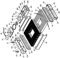
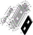
Fig. 1 is an exploded view of a first preferred embodiment of the present invention;
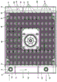
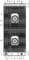
FIG. 2 is a top view of a first preferred embodiment of the present invention;
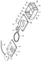
fig. 3 is a partially enlarged exploded view of the first preferred embodiment of the present invention;
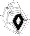
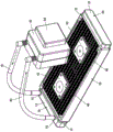
FIG. 4 is a perspective view of the first preferred embodiment of the present invention in a use state;
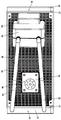
FIG. 5 is a top view of a first preferred embodiment of the present invention;
fig. 6 is an exploded view of a second preferred embodiment of the present invention;
FIG. 7 is a top view of a second preferred embodiment of the present invention;
fig. 8 is a partially enlarged exploded view of a second preferred embodiment of the present invention;
FIG. 9 is a perspective view of a second preferred embodiment of the present invention;
fig. 10 is a top view of a second preferred embodiment of the present invention.
The attached drawings indicate the following:
10. splitter box 11 and first splitter water-stop sheet
12. First box body 13 and first box cover
101. Water inlet chamber 102 and transition chamber
103. Water outlet chamber 104, water inlet
105. Water outlet hole 106 and first mounting groove
107. Second mounting groove 108 and third mounting groove
20. Water collecting tank 21, second flow dividing water-stop sheet
22. Second box body 23, second box cover
201. First water collecting cavity 202 and second water collecting cavity
203. A fourth mounting groove 204 and a fifth mounting groove
31. First row of tubes 32, second row of tubes
33. Third bank of tubes 34, fourth bank of tubes
40. Pumping device 41 and main box body
411. Bottom case 412, top cover
42. Water pump cover 421, concave
43. Main water stop sheet 431 and third through hole
44. Water pump 45, impeller
46. Sealing washer 47, PCB board
48. Power line 401 and water pump cavity
402. Water inlet cavity 403 and water outlet cavity
404. Sixth mounting groove 405, seventh mounting groove
406. First fixing hole 407 and second fixing hole
408. A first through hole 409 and a second through hole
51. Water inlet pipe joint 52 and water outlet pipe joint
60. Heat radiation fin 70 and fan fixing support
81. Water inlet pipe 82 and water outlet pipe
83. Water cooling head 84, electronic components.
Detailed Description
Referring to fig. 1 to 5, a detailed structure of a first preferred embodiment of the present invention is shown, which includes a diversion trench 10, a water collection tank 20, a first row of pipes 31, a second row of pipes 32, a third row of pipes 33, a fourth row of pipes 34, and a pumping device 40.
This splitter box 10 is the heat dissipation metal material, be provided with a plurality of first splitter water-stop sheets 11 in the splitter box 10 and separate the inside of splitter box 10 and be formed with intake chamber 101, transition cavity 102 and play water chamber 103, the inlet opening 104 has been seted up on this splitter box 10, apopore 105, first mounting groove 106, second mounting groove 107 and third mounting groove 108, this inlet opening 104 and first mounting groove 106 all communicate intake chamber 101, this apopore 105 and second mounting groove 107 all communicate play water chamber 103, this third mounting groove 108 intercommunication transition cavity 102. Specifically, the diversion trench 10 includes a first box body 12 and a first box cover 13, the first diversion water-stop sheet 11 is disposed in the first box body 12 by welding or integral molding, the first box cover 13 is fixed to the first box body 12 in a sealing manner and encloses to form the water inlet chamber 101, the transition chamber 102 and the water outlet chamber 103, the water inlet hole 104 and the water outlet hole 105 are disposed on the first box body 12, the water inlet hole 104 is hermetically provided with a water inlet pipe joint 51, and the water outlet hole 105 is hermetically provided with a water outlet pipe joint 52; the first, second and third mounting grooves 106, 107 and 108 are formed in the first cover 13. And the water inlet pipe joint 51 is inserted into the water inlet hole 104 and is fixedly and hermetically mounted with the first box body 12 by welding, the water outlet pipe joint 52 is inserted into the water outlet hole 105 and is fixedly and hermetically mounted with the first box body 12 by welding, the first box body 12 and the first box cover 13 are made of copper or aluminum, and the first box cover 13 is fixedly and hermetically mounted with the first box body 12 by welding.
The water collection tank 20 is also made of heat dissipation metal, a plurality of second diversion water stop plates 21 are arranged in the water collection tank 20 to separate the inside of the water collection tank 20 into a first water collection chamber 201 and a second water collection chamber 202, a fourth installation groove 203 and a fifth installation groove 204 are formed in the water collection tank 20, the fourth installation groove 203 is communicated with the first water collection chamber 201, and the fifth installation groove 204 is communicated with the second water collection chamber 202. Specifically, the water collecting tank 20 includes a second box body 22 and a second box cover 23, the second diversion water-stop sheet 21 is disposed in the second box body 22 by welding or integral molding, and the second box cover 23 and the second box body 22 are sealed and fixed and form the first water collecting chamber 201 and the second water collecting chamber 202; the fourth mounting groove 203 and the fifth mounting groove 204 are both arranged on the second box cover 23; the second box 22 and the second box cover 23 are made of copper or aluminum, and the second box cover 23 is fixedly installed with the second box 22 in a sealing mode through welding.
The first row pipe 31, the second row pipe 32, the third row pipe 33 and the fourth row pipe 34 are all provided with radiating fins 60; in this embodiment, the first, second, third and fourth rows of tubes 31, 32, 33 and 34 are all heat dissipating metal flat tubes, but may be heat dissipating metal round tubes, and not limited thereto, and both ends of the first, second, third and fourth rows of tubes 31, 32, 33 and 34 are respectively welded and fixed to the diversion channel 10 and the water collection channel 20. Specifically, the method comprises the following steps:
one end of the first discharge pipe 31 is hermetically installed in the first installation groove 106 and communicated with the water inlet chamber 101, and the other end of the first discharge pipe 31 is hermetically installed in the corresponding fourth installation groove 203 and communicated with the first water collection chamber 201; in the present embodiment, the first exhaust pipes 31 are two pipes arranged side by side at intervals, which is not limited.
One end of the second row of tubes 32 is hermetically installed in the corresponding third installation groove 108 and communicated with the transition chamber 102, and the other end of the second row of tubes 32 is hermetically installed in the corresponding fourth installation groove 203 and communicated with the first water collection chamber 201; in the present embodiment, the second row of tubes 32 is two tubes that are arranged side by side at intervals, which is not limited.
One end of the third row of tubes 33 is hermetically installed in the third installation groove 108 and communicated with the transition chamber 102, the other end of the third row of tubes 33 is hermetically installed in the corresponding fifth installation groove 204 and communicated with the second water collection chamber 202, the third row of tubes 33 is formed with at least two sections in a broken way, in the embodiment, the third row of tubes 33 is formed with a front section and a rear section in a broken way; in this embodiment, the third row of tubes 33 is four tubes arranged side by side at intervals, which is not limited.
One end of the fourth row of tubes 34 is hermetically installed in the second installation groove 107 and communicated with the water outlet chamber 103, and the other end of the fourth row of tubes 34 is hermetically installed in the corresponding fifth installation groove 204 and communicated with the second water collection chamber 202; in the present embodiment, the fourth row of tubes 34 is four tubes that are arranged side by side at intervals, which is not limited.
The pumping device 40 is integrally arranged between two adjacent third discharge pipes 33, and the pumping device 40 comprises a main box body 41 and a water pump cover 42; the main box body 41 is also made of heat-dissipating metal materials, a water pump cavity 401 is arranged in the main box body 41, a main water-stop plate 43 is arranged in the main box body 41, the main water-stop plate 43 separates the interior of the main box body 41 to form a water inlet cavity 402 and a water outlet cavity 403 which are isolated from each other, the water outlet cavity 403 is communicated with the water pump cavity 401, a sixth installation groove 404 communicated with the water inlet cavity 402 is formed in one side of the main box body 41, a seventh installation groove 405 communicated with the water outlet cavity 403 is formed in the other side of the main box body 41, and the end parts of two adjacent third discharge pipes 33 are respectively and hermetically installed in the sixth installation groove 404 and the seventh installation groove 405 and are communicated with the water inlet cavity 402 and the water outlet cavity 403; the water pump cover 42 is fixed with the main box body 41 and seals the opening of the water pump cavity 401, the water pump 44 is fixed on the inner side of the water pump cover 42, the impeller 45 is fixed on the output shaft of the water pump 44, and the impeller 45 is positioned in the water pump cavity 401 and is driven by the water pump 44 to rotate.
In this embodiment, the main box 41 includes a bottom box 411 and a top cover 412, the main water-stop sheet 43 is located in the bottom box 411 and is disposed in the bottom box 411 by welding or integral molding, the water inlet cavity 402 and the water outlet cavity 403 are formed in the bottom box 411, openings of the water inlet cavity 402 and the water outlet cavity 403 are both upward, and the sixth installation groove 404 and the seventh installation groove 405 are respectively located on two side surfaces of the bottom box 411; the top cover 412 and the bottom case 411 are fixed and seal the openings of the water inlet cavity 402 and the water outlet cavity 403, the water pump cavity 401 is formed on the top cover 412, in addition, each corner of the top cover 412 is provided with a first fixing hole 406, each corner of the bottom case 411 is provided with a second fixing hole 407, and a fixing screw passes through the first fixing hole 406 and is fixedly connected with the second fixing hole 407; the water pump cover 42 is fixed to the top cover 412 in a sealing manner, and in the present embodiment, a sealing gasket 46 is interposed between the water pump cover 42 and the top cover 412; the top surface of the top cover 412 is recessed downward to form the water pump cavity 401, the inner bottom surface of the water pump cavity 401 is provided with a first through hole 408, the first through hole 408 is communicated with the water inlet cavity 402, the inner peripheral side wall of the water pump cavity 401 is provided with a second through hole 409, the main water stop plate 43 is provided with a third through hole 431, and the third through hole 431 is in opposite communication with the second through hole 409; in addition, the concave position 421 that is equipped with of top surface of water pump cover 42, inlays in this concave position 421 and is equipped with PCB board 47, and this PCB board 47 and water pump 44 conducting connection, and PCB board 47 are connected with power cord 48, and this power cord 48 is used for being connected with external power source.
In addition, two fan fixing brackets 70 are connected between the diversion channel 10 and the water collection channel 20, the two fan fixing brackets 70 are arranged left and right, and the first row of tubes 31, the second row of tubes 32, the third row of tubes 33 and the fourth row of tubes 34 are located between the two fan fixing brackets 70, so that the whole structure of the product is more stable, and the fixed fans can be installed.
Detailed description the working principle of the present embodiment is as follows:
when the water cooling device is used, as shown in fig. 4 and 5, the water inlet pipe joint 51 and the water outlet pipe joint 52 are respectively connected with the water inlet pipe 81 and the water outlet pipe 82, the water inlet pipe 81 and the water outlet pipe 82 are respectively communicated with the water outlet and the water inlet of the water cooling head 83, and the electronic part 84 is attached and fixed on the water cooling head 83. During operation, the temperature of water in the water cooling head 83 is increased by heat generated by the operation of the electronic component 84, the water with higher temperature is output from the water outlet of the water cooling head 83 and enters the water inlet pipe joint 51 through the water inlet pipe 81, then enters the water inlet cavity 101, then sequentially flows through the first discharge pipe 31, the first water collecting cavity 201, the second discharge pipe 32, the transition cavity 102, the third discharge pipe 33, the second water collecting cavity 202, the fourth discharge pipe 34 and the water outlet cavity 103, finally the water is output from the water outlet pipe joint 52, the water obtains power by the pumping device 40 when flowing through the third discharge pipe 33, so that the water can accelerate the flow passage, the temperature of the water is gradually reduced in the process of flowing through the water inlet cavity 101, the first discharge pipe 31, the first water collecting cavity 201, the second discharge pipe 32, the transition cavity 102, the third discharge pipe 33, the pumping device 40, the second water collecting cavity 202, the fourth discharge pipe 34 and the water outlet cavity 103, the temperature of the water output from the water outlet pipe joint 52 is low, so that a good cooling and heat dissipation effect is achieved, the water with low temperature is conveyed into the water cooling head 83 through the water outlet pipe 82, heat generated by the electronic part 84 is continuously absorbed, the temperature of the electronic part 84 is kept in a low state, the electronic part 84 is stable in operation, and abnormal operation caused by overhigh temperature can be avoided.
Referring to fig. 6 to 10, a specific structure of a second preferred embodiment of the present invention is shown, which is basically the same as the specific structure of the first preferred embodiment, except that:
in this embodiment, the third row of tubes 33 is broken to form three sections, and the pumping device 40 is integrally disposed between every two adjacent sections of the third row of tubes 33, so that the two pumping devices 40 are disposed to further increase the flowing speed of water in the third row of tubes 33, thereby further improving the heat dissipation efficiency and achieving a better heat dissipation effect.
The operation principle of this embodiment is basically the same as that of the first preferred embodiment, and the operation principle of this embodiment will not be described in detail here.
The utility model discloses a design focus lies in: form a plurality of cavities through all being provided with the reposition of redundant personnel water-stop sheet in diverging channel and water catch bowl to the cooperation sets up the corresponding cavity of each calandria intercommunication, make the runner in this product be a plurality of circuitous structures that connect gradually, effectively prolonged the flow stroke of water in the water-cooling is arranged, make hydroenergy enough fully cool down the heat dissipation effectively, and, through being provided with pumping installations, utilize pumping installations, can effectively accelerate the flow speed of water, improve the radiating efficiency, the whole radiating effect of this product is very good.
The above description is only a preferred embodiment of the present invention, and is not intended to limit the technical scope of the present invention, so that any slight modifications, equivalent changes and modifications made by the technical spirit of the present invention to the above embodiments are all within the scope of the technical solution of the present invention.
Claims (10)
1. The utility model provides a many catchments of multithread way of intaking box adds liquid cooling heat dissipation log raft of water pump which characterized in that: the device comprises a flow distribution groove, a water collection groove, a first calandria, a second calandria, a third calandria, a fourth calandria and a pumping device;
the splitter box is made of heat dissipation metal materials, a plurality of first splitter water-stop plates are arranged in the splitter box to divide the interior of the splitter box into a water inlet cavity, a transition cavity and a water outlet cavity, a water inlet hole, a water outlet hole, a first mounting groove, a second mounting groove and a third mounting groove are formed in the splitter box, the water inlet hole and the first mounting groove are communicated with the water inlet cavity, the water outlet hole and the second mounting groove are communicated with the water outlet cavity, and the third mounting groove is communicated with the transition cavity;
the water collecting tank is also made of heat dissipation metal materials, a plurality of second flow dividing water-stop plates are arranged in the water collecting tank to separate the interior of the water collecting tank into a first water collecting cavity and a second water collecting cavity, a fourth mounting groove and a fifth mounting groove are formed in the water collecting tank, the fourth mounting groove is communicated with the first water collecting cavity, and the fifth mounting groove is communicated with the second water collecting cavity;
the first, second, third and fourth rows of tubes are all provided with heat radiating fins; one end of the first calandria is hermetically arranged in the first mounting groove and communicated with the water inlet cavity, and the other end of the first calandria is hermetically arranged in the corresponding fourth mounting groove and communicated with the first water collecting cavity; one end of the second calandria is hermetically arranged in the corresponding third mounting groove and communicated with the transition chamber, and the other end of the second calandria is hermetically arranged in the corresponding fourth mounting groove and communicated with the first water collecting chamber; one end of the third calandria is hermetically arranged in the third mounting groove and communicated with the transition chamber, the other end of the third calandria is hermetically arranged in the corresponding fifth mounting groove and communicated with the second water collecting chamber, and the third calandria is disconnected to form at least two sections; one end of the fourth calandria is hermetically arranged in the second mounting groove and communicated with the water outlet cavity, and the other end of the fourth calandria is hermetically arranged in the corresponding fifth mounting groove and communicated with the second water collecting cavity;
the pumping device is integrally arranged between two adjacent third discharge pipes and comprises a main box body and a water pump cover; the main box body is also made of heat dissipation metal materials, a water pump cavity is arranged in the main box body, a main water-stop plate is arranged in the main box body, the main water-stop plate divides the interior of the main box body to form a water inlet cavity and a water outlet cavity which are isolated from each other, the water outlet cavity is communicated with the water pump cavity, a sixth mounting groove communicated with the water inlet cavity is formed in one side of the main box body, a seventh mounting groove communicated with the water outlet cavity is formed in the other side of the main box body, and the end parts of two adjacent third calandria pipes are respectively and hermetically mounted in the sixth mounting groove and the seventh mounting groove and are communicated with the water inlet cavity and the water outlet cavity; the water pump cover is fixed with the main box body and covers the opening of the water pump cavity in a sealing mode, the water pump is fixed on the inner side of the water pump cover, an impeller is fixed on an output shaft of the water pump, and the impeller is located in the water pump cavity and driven by the water pump to rotate.
2. The liquid-cooled radiator water discharge of the water inlet multi-runner multi-collector box water pump according to claim 1, wherein: the main box body comprises a bottom box and a top cover, the main water-stop sheet is positioned in the bottom box and is arranged in the bottom box in a welding or integrated forming mode, the water inlet cavity and the water outlet cavity are formed in the bottom box, the openings of the water inlet cavity and the water outlet cavity are upward, and the sixth mounting groove and the seventh mounting groove are respectively positioned on two side surfaces of the bottom box; the top cover and the bottom box are fixed and seal the openings of the water inlet cavity and the water outlet cavity, and the water pump cavity is formed on the top cover; the water pump cover is fixed with the top cover in a sealing way.
3. The liquid-cooled radiator water discharge of the water inlet multi-runner multi-collector box water pump according to claim 2, wherein: the top surface of the top cover is recessed to form the water pump cavity, a first through hole is formed in the inner bottom surface of the water pump cavity and communicated with the water inlet cavity, a second through hole is formed in the inner peripheral side wall of the water pump cavity, a third through hole is formed in the main water-stop plate, and the third through hole is communicated with the second through hole in a right-to-right mode.
4. The liquid-cooled radiator water discharge of the water inlet multi-runner multi-collector box water pump according to claim 1, wherein: the top surface of water pump cover is concave to be equipped with concave position, inlays in this concave position and is equipped with the PCB board, and this PCB board and water pump conducting connection, and the PCB board is connected with the power cord.
5. The liquid-cooled radiator water discharge of the water inlet multi-runner multi-collector box water pump according to claim 1, wherein: the splitter box is including first box body and first lid, and aforementioned first reposition of redundant personnel water-stop sheet sets up in first box body through welding or integrated into one piece's mode, and this first lid is fixed with first box body seal and encloses the constitution and become aforementioned intake cavity, transition cavity and play water cavity, and, this first box body and first lid are copper or aluminium material, and this first lid is fixed through welding and first box body seal installation.
6. The liquid-cooled radiator water discharge of the water inlet multi-runner multi-collector box water pump according to claim 5, wherein: the water inlet hole and the water outlet hole are both arranged on the first box body, a water inlet pipe connector is hermetically arranged in the water inlet hole, and a water outlet pipe connector is hermetically arranged in the water outlet hole; this first mounting groove, second mounting groove and third mounting groove all set up on first box cover, and, this water pipe connector inserts in the inlet opening and fixed through welding and first box body seal installation, and this water pipe connector inserts in the apopore and fixes through welding and first box body seal installation.
7. The liquid-cooled radiator water discharge of the water inlet multi-runner multi-collector box water pump according to claim 1, wherein: the water catch bowl sets up in the second box body including second box body and second lid, aforementioned second reposition of redundant personnel water-stop sheet through welding or integrated into one piece's mode, and this second lid forms aforementioned first water-collecting cavity and second water-collecting cavity with second box body sealing fixation and enclosure, and, this second box body and second lid are copper or aluminium material, and this second lid is fixed through welding and second box body sealing installation.
8. The liquid-cooled radiator water discharge of the water inlet multi-runner multi-collector box water pump according to claim 7, wherein: and the fourth mounting groove and the fifth mounting groove are both arranged on the second box cover.
9. The liquid-cooled radiator water discharge of the water inlet multi-runner multi-collector box water pump according to claim 1, wherein: the utility model discloses a fan rack, including splitter box, water catch bowl, first calandria, second calandria, third calandria, fourth calandria, first calandria, second calandria, third calandria and fourth calandria, be connected with two fan fixed bolster between splitter box and the water catch bowl, set up about two fan fixed bolsters, and this first calandria, second calandria, third calandria and fourth calandria are between two fan fixed bolsters, and this first calandria, second calandria, third calandria and fourth calandria are heat dissipation metal flat tube or heat dissipation metal pipe, and first calandria and second calandria are two, and third calandria and fourth calandria are four.
10. The liquid-cooled radiator water discharge of the water inlet multi-runner multi-collector box water pump according to claim 1, wherein: the third calandria is broken to form three sections, and the pumping device is integrally arranged between every two adjacent sections of the third calandria.
Priority Applications (1)
| Application Number | Priority Date | Filing Date | Title |
|---|---|---|---|
| CN202022925061.2U CN214407066U (en) | 2020-12-09 | 2020-12-09 | Liquid cooling radiating water discharge of water inlet multi-runner multi-water collecting box water adding pump |
Applications Claiming Priority (1)
| Application Number | Priority Date | Filing Date | Title |
|---|---|---|---|
| CN202022925061.2U CN214407066U (en) | 2020-12-09 | 2020-12-09 | Liquid cooling radiating water discharge of water inlet multi-runner multi-water collecting box water adding pump |
Publications (1)
| Publication Number | Publication Date |
|---|---|
| CN214407066U true CN214407066U (en) | 2021-10-15 |
Family
ID=78037322
Family Applications (1)
| Application Number | Title | Priority Date | Filing Date |
|---|---|---|---|
| CN202022925061.2U Active CN214407066U (en) | 2020-12-09 | 2020-12-09 | Liquid cooling radiating water discharge of water inlet multi-runner multi-water collecting box water adding pump |
Country Status (1)
| Country | Link |
|---|---|
| CN (1) | CN214407066U (en) |
-
2020
- 2020-12-09 CN CN202022925061.2U patent/CN214407066U/en active Active
Similar Documents
| Publication | Publication Date | Title |
|---|---|---|
| CN112393626A (en) | Liquid cooling radiating water discharge of water inlet multi-runner multi-water collecting box water adding pump | |
| CN112414164A (en) | Multi-runner type efficient radiating water-cooling radiator | |
| TWI765680B (en) | Vertical liquid cooling radiator | |
| CN112444050A (en) | Integral cavity type water cooling drainage with built-in water pump | |
| CN113809027B (en) | Water-cooling radiator with built-in semiconductor refrigerating system and fan | |
| CN114371768A (en) | Water-cooling radiating water drain with single water drain and built-in double water pumps | |
| CN111799238B (en) | Double-sided water-cooling IGBT radiator and radiating installation structure thereof | |
| CN116931698B (en) | Integrated liquid cooling radiator | |
| CN211406687U (en) | Communication cabinet capable of dissipating heat quickly | |
| TWM609012U (en) | Liquid cooling system | |
| CN214407066U (en) | Liquid cooling radiating water discharge of water inlet multi-runner multi-water collecting box water adding pump | |
| CN214708446U (en) | Integrated liquid cooling radiator | |
| CN217787721U (en) | Water-cooled heat abstractor | |
| CN216982363U (en) | Liquid cooling type heat radiation module | |
| CN214407068U (en) | Multi-runner type efficient radiating water-cooling radiator | |
| CN113593616A (en) | Heat dissipation device for memory | |
| CN215113450U (en) | Integral cavity type water cooling drainage with built-in water pump | |
| CN211429871U (en) | Radiator and radiating structure | |
| CN217308121U (en) | Liquid cooling box type radiator | |
| CN112467170B (en) | Heat radiator | |
| CN212727288U (en) | Convergence switch | |
| CN218395870U (en) | Die-casting box | |
| CN217770705U (en) | Control cabinet | |
| CN220705917U (en) | Water cooling system heat abstractor of pump group | |
| CN220755363U (en) | Module power supply heat dissipation assembly |
Legal Events
| Date | Code | Title | Description |
|---|---|---|---|
| GR01 | Patent grant | ||
| GR01 | Patent grant |