CN112414164A - Multi-runner type efficient radiating water-cooling radiator - Google Patents
Multi-runner type efficient radiating water-cooling radiator Download PDFInfo
- Publication number
- CN112414164A CN112414164A CN202011417465.9A CN202011417465A CN112414164A CN 112414164 A CN112414164 A CN 112414164A CN 202011417465 A CN202011417465 A CN 202011417465A CN 112414164 A CN112414164 A CN 112414164A
- Authority
- CN
- China
- Prior art keywords
- water
- cavity
- mounting groove
- calandria
- communicated
- Prior art date
- Legal status (The legal status is an assumption and is not a legal conclusion. Google has not performed a legal analysis and makes no representation as to the accuracy of the status listed.)
- Pending
Links
Images


Classifications
-
- F—MECHANICAL ENGINEERING; LIGHTING; HEATING; WEAPONS; BLASTING
- F28—HEAT EXCHANGE IN GENERAL
- F28D—HEAT-EXCHANGE APPARATUS, NOT PROVIDED FOR IN ANOTHER SUBCLASS, IN WHICH THE HEAT-EXCHANGE MEDIA DO NOT COME INTO DIRECT CONTACT
- F28D1/00—Heat-exchange apparatus having stationary conduit assemblies for one heat-exchange medium only, the media being in contact with different sides of the conduit wall, in which the other heat-exchange medium is a large body of fluid, e.g. domestic or motor car radiators
- F28D1/02—Heat-exchange apparatus having stationary conduit assemblies for one heat-exchange medium only, the media being in contact with different sides of the conduit wall, in which the other heat-exchange medium is a large body of fluid, e.g. domestic or motor car radiators with heat-exchange conduits immersed in the body of fluid
- F28D1/04—Heat-exchange apparatus having stationary conduit assemblies for one heat-exchange medium only, the media being in contact with different sides of the conduit wall, in which the other heat-exchange medium is a large body of fluid, e.g. domestic or motor car radiators with heat-exchange conduits immersed in the body of fluid with tubular conduits
- F28D1/053—Heat-exchange apparatus having stationary conduit assemblies for one heat-exchange medium only, the media being in contact with different sides of the conduit wall, in which the other heat-exchange medium is a large body of fluid, e.g. domestic or motor car radiators with heat-exchange conduits immersed in the body of fluid with tubular conduits the conduits being straight
- F28D1/0535—Heat-exchange apparatus having stationary conduit assemblies for one heat-exchange medium only, the media being in contact with different sides of the conduit wall, in which the other heat-exchange medium is a large body of fluid, e.g. domestic or motor car radiators with heat-exchange conduits immersed in the body of fluid with tubular conduits the conduits being straight the conduits having a non-circular cross-section
- F28D1/05366—Assemblies of conduits connected to common headers, e.g. core type radiators
- F28D1/05375—Assemblies of conduits connected to common headers, e.g. core type radiators with particular pattern of flow, e.g. change of flow direction
-
- F—MECHANICAL ENGINEERING; LIGHTING; HEATING; WEAPONS; BLASTING
- F28—HEAT EXCHANGE IN GENERAL
- F28F—DETAILS OF HEAT-EXCHANGE AND HEAT-TRANSFER APPARATUS, OF GENERAL APPLICATION
- F28F1/00—Tubular elements; Assemblies of tubular elements
- F28F1/10—Tubular elements and assemblies thereof with means for increasing heat-transfer area, e.g. with fins, with projections, with recesses
- F28F1/12—Tubular elements and assemblies thereof with means for increasing heat-transfer area, e.g. with fins, with projections, with recesses the means being only outside the tubular element
- F28F1/14—Tubular elements and assemblies thereof with means for increasing heat-transfer area, e.g. with fins, with projections, with recesses the means being only outside the tubular element and extending longitudinally
- F28F1/22—Tubular elements and assemblies thereof with means for increasing heat-transfer area, e.g. with fins, with projections, with recesses the means being only outside the tubular element and extending longitudinally the means having portions engaging further tubular elements
-
- F—MECHANICAL ENGINEERING; LIGHTING; HEATING; WEAPONS; BLASTING
- F28—HEAT EXCHANGE IN GENERAL
- F28F—DETAILS OF HEAT-EXCHANGE AND HEAT-TRANSFER APPARATUS, OF GENERAL APPLICATION
- F28F9/00—Casings; Header boxes; Auxiliary supports for elements; Auxiliary members within casings
- F28F9/02—Header boxes; End plates
- F28F9/0202—Header boxes having their inner space divided by partitions
- F28F9/0204—Header boxes having their inner space divided by partitions for elongated header box, e.g. with transversal and longitudinal partitions
- F28F9/0209—Header boxes having their inner space divided by partitions for elongated header box, e.g. with transversal and longitudinal partitions having only transversal partitions
-
- F—MECHANICAL ENGINEERING; LIGHTING; HEATING; WEAPONS; BLASTING
- F28—HEAT EXCHANGE IN GENERAL
- F28F—DETAILS OF HEAT-EXCHANGE AND HEAT-TRANSFER APPARATUS, OF GENERAL APPLICATION
- F28F9/00—Casings; Header boxes; Auxiliary supports for elements; Auxiliary members within casings
- F28F9/02—Header boxes; End plates
- F28F9/0219—Arrangements for sealing end plates into casing or header box; Header box sub-elements
- F28F9/0224—Header boxes formed by sealing end plates into covers
-
- F—MECHANICAL ENGINEERING; LIGHTING; HEATING; WEAPONS; BLASTING
- F28—HEAT EXCHANGE IN GENERAL
- F28F—DETAILS OF HEAT-EXCHANGE AND HEAT-TRANSFER APPARATUS, OF GENERAL APPLICATION
- F28F9/00—Casings; Header boxes; Auxiliary supports for elements; Auxiliary members within casings
- F28F9/02—Header boxes; End plates
- F28F9/0246—Arrangements for connecting header boxes with flow lines
- F28F9/0248—Arrangements for sealing connectors to header boxes
-
- F—MECHANICAL ENGINEERING; LIGHTING; HEATING; WEAPONS; BLASTING
- F28—HEAT EXCHANGE IN GENERAL
- F28F—DETAILS OF HEAT-EXCHANGE AND HEAT-TRANSFER APPARATUS, OF GENERAL APPLICATION
- F28F9/00—Casings; Header boxes; Auxiliary supports for elements; Auxiliary members within casings
- F28F9/02—Header boxes; End plates
- F28F9/04—Arrangements for sealing elements into header boxes or end plates
- F28F9/16—Arrangements for sealing elements into header boxes or end plates by permanent joints, e.g. by rolling
- F28F9/18—Arrangements for sealing elements into header boxes or end plates by permanent joints, e.g. by rolling by welding
-
- F—MECHANICAL ENGINEERING; LIGHTING; HEATING; WEAPONS; BLASTING
- F28—HEAT EXCHANGE IN GENERAL
- F28F—DETAILS OF HEAT-EXCHANGE AND HEAT-TRANSFER APPARATUS, OF GENERAL APPLICATION
- F28F9/00—Casings; Header boxes; Auxiliary supports for elements; Auxiliary members within casings
- F28F9/26—Arrangements for connecting different sections of heat-exchange elements, e.g. of radiators
- F28F9/262—Arrangements for connecting different sections of heat-exchange elements, e.g. of radiators for radiators
- F28F9/268—Arrangements for connecting different sections of heat-exchange elements, e.g. of radiators for radiators by permanent joints, e.g. by welding
-
- F—MECHANICAL ENGINEERING; LIGHTING; HEATING; WEAPONS; BLASTING
- F28—HEAT EXCHANGE IN GENERAL
- F28D—HEAT-EXCHANGE APPARATUS, NOT PROVIDED FOR IN ANOTHER SUBCLASS, IN WHICH THE HEAT-EXCHANGE MEDIA DO NOT COME INTO DIRECT CONTACT
- F28D21/00—Heat-exchange apparatus not covered by any of the groups F28D1/00 - F28D20/00
- F28D2021/0019—Other heat exchangers for particular applications; Heat exchange systems not otherwise provided for
- F28D2021/0028—Other heat exchangers for particular applications; Heat exchange systems not otherwise provided for for cooling heat generating elements, e.g. for cooling electronic components or electric devices
- F28D2021/0031—Radiators for recooling a coolant of cooling systems
-
- F—MECHANICAL ENGINEERING; LIGHTING; HEATING; WEAPONS; BLASTING
- F28—HEAT EXCHANGE IN GENERAL
- F28F—DETAILS OF HEAT-EXCHANGE AND HEAT-TRANSFER APPARATUS, OF GENERAL APPLICATION
- F28F1/00—Tubular elements; Assemblies of tubular elements
- F28F1/02—Tubular elements of cross-section which is non-circular
- F28F1/04—Tubular elements of cross-section which is non-circular polygonal, e.g. rectangular
- F28F1/045—Tubular elements of cross-section which is non-circular polygonal, e.g. rectangular with assemblies of stacked elements
-
- F—MECHANICAL ENGINEERING; LIGHTING; HEATING; WEAPONS; BLASTING
- F28—HEAT EXCHANGE IN GENERAL
- F28F—DETAILS OF HEAT-EXCHANGE AND HEAT-TRANSFER APPARATUS, OF GENERAL APPLICATION
- F28F9/00—Casings; Header boxes; Auxiliary supports for elements; Auxiliary members within casings
- F28F9/02—Header boxes; End plates
- F28F9/0219—Arrangements for sealing end plates into casing or header box; Header box sub-elements
- F28F9/0221—Header boxes or end plates formed by stacked elements
-
- F—MECHANICAL ENGINEERING; LIGHTING; HEATING; WEAPONS; BLASTING
- F28—HEAT EXCHANGE IN GENERAL
- F28F—DETAILS OF HEAT-EXCHANGE AND HEAT-TRANSFER APPARATUS, OF GENERAL APPLICATION
- F28F9/00—Casings; Header boxes; Auxiliary supports for elements; Auxiliary members within casings
- F28F9/02—Header boxes; End plates
- F28F9/026—Header boxes; End plates with static flow control means, e.g. with means for uniformly distributing heat exchange media into conduits
- F28F9/027—Header boxes; End plates with static flow control means, e.g. with means for uniformly distributing heat exchange media into conduits in the form of distribution pipes
-
- F—MECHANICAL ENGINEERING; LIGHTING; HEATING; WEAPONS; BLASTING
- F28—HEAT EXCHANGE IN GENERAL
- F28F—DETAILS OF HEAT-EXCHANGE AND HEAT-TRANSFER APPARATUS, OF GENERAL APPLICATION
- F28F9/00—Casings; Header boxes; Auxiliary supports for elements; Auxiliary members within casings
- F28F9/02—Header boxes; End plates
- F28F9/04—Arrangements for sealing elements into header boxes or end plates
- F28F9/16—Arrangements for sealing elements into header boxes or end plates by permanent joints, e.g. by rolling
- F28F9/18—Arrangements for sealing elements into header boxes or end plates by permanent joints, e.g. by rolling by welding
- F28F9/182—Arrangements for sealing elements into header boxes or end plates by permanent joints, e.g. by rolling by welding the heat-exchange conduits having ends with a particular shape, e.g. deformed; the heat-exchange conduits or end plates having supplementary joining means, e.g. abutments
Abstract
The invention discloses a multi-runner efficient radiating water-cooling bar which comprises a flow dividing groove, a water collecting groove, a first pipe, a second pipe, a third pipe and a fourth pipe; this splitter box is the heat dissipation metal material, be provided with a plurality of first reposition of redundant personnel water-stop sheets in the splitter box and be formed with the inside partition of splitter box into the cavity, transition cavity and play water cavity, this water catch bowl also is the heat dissipation metal material, be provided with a plurality of second reposition of redundant personnel water-stop sheets in the water catch bowl and be formed with first catchment cavity and second catchment cavity with the inside partition of water catch bowl, all be provided with the reposition of redundant personnel water-stop sheet and form a plurality of cavities through in splitter box and catchment box, and the cooperation sets up the corresponding cavity of each calandria intercommunication, make the runner in this product be a plurality of circuitous structures that connect gradually, the flow stroke of water in the water-cooling row has effectively been prolonged, make hydroenergy effectively fully cool down the heat dissipation, the whole radiating effect of product is very.
Description
Technical Field
The invention relates to the technical field of radiators, in particular to a multi-channel efficient radiating water-cooling radiator.
Background
The water-cooled radiator is driven by a pump to forcibly circulate liquid to take away heat of the radiator, and has the advantages of quiet, stable cooling, small dependence on the environment and the like compared with air cooling. The heat dissipation performance of a water-cooled heat sink is proportional to the flow rate of the cooling fluid (water or other liquid) therein, which in turn is related to the power of the water pump of the refrigeration system. And the heat capacity of water is large, so that the water-cooling refrigerating system has good heat load capacity.
The existing water-cooled radiator generally comprises a water-cooled radiator, a water-cooled head and a water pipe, wherein the water pipe is connected between the water-cooled radiator and the water-cooled head, the water pipe is used for enabling water in the water-cooled radiator and the water-cooled head to circularly flow, the water enters the water-cooled radiator for heat dissipation after absorbing heat on the water-cooled head, and the water after heat dissipation flows back to the water-cooled head.
In the prior art, the flow channel of the water-cooling row of the water-cooling radiator is U-shaped, so that the flow stroke of water in the water-cooling row is short, and the water cannot be effectively cooled and radiated. Therefore, there is a need for improvements in current water cooled rows.
Disclosure of Invention
In view of the above, the present invention is directed to the defects in the prior art, and the main objective of the present invention is to provide a multi-channel high-efficiency heat dissipation water cooling bar, which can effectively solve the problem that the existing water cooling bar cannot effectively cool and dissipate heat of water.
In order to achieve the purpose, the invention adopts the following technical scheme:
a multi-runner high-efficiency heat-dissipation water-cooling bar comprises a flow distribution groove, a water collection groove, a first pipe, a second pipe, a third pipe and a fourth pipe;
the splitter box is made of heat dissipation metal materials, a plurality of first splitter water-stop plates are arranged in the splitter box to divide the interior of the splitter box into a water inlet cavity, a transition cavity and a water outlet cavity, a water inlet hole, a water outlet hole, a first mounting groove, a second mounting groove and a third mounting groove are formed in the splitter box, the water inlet hole and the first mounting groove are communicated with the water inlet cavity, the water outlet hole and the second mounting groove are communicated with the water outlet cavity, and the third mounting groove is communicated with the transition cavity;
the water collecting tank is also made of heat dissipation metal materials, a plurality of second flow dividing water-stop plates are arranged in the water collecting tank to separate the interior of the water collecting tank into a first water collecting cavity and a second water collecting cavity, a fourth mounting groove and a fifth mounting groove are formed in the water collecting tank, the fourth mounting groove is communicated with the first water collecting cavity, and the fifth mounting groove is communicated with the second water collecting cavity;
the first, second, third and fourth rows of tubes are all provided with heat radiating fins; one end of the first calandria is hermetically arranged in the first mounting groove and communicated with the water inlet cavity, and the other end of the first calandria is hermetically arranged in the corresponding fourth mounting groove and communicated with the first water collecting cavity; one end of the second calandria is hermetically arranged in the corresponding third mounting groove and communicated with the transition chamber, and the other end of the second calandria is hermetically arranged in the corresponding fourth mounting groove and communicated with the first water collecting chamber; one end of the third calandria is hermetically arranged in the third mounting groove and communicated with the transition chamber, and the other end of the third calandria is hermetically arranged in the corresponding fifth mounting groove and communicated with the second water collecting chamber; one end of the fourth calandria is hermetically arranged in the second mounting groove and communicated with the water outlet cavity, and the other end of the fourth calandria is hermetically arranged in the corresponding fifth mounting groove and communicated with the second water collecting cavity.
As a preferred scheme, the number of the transition chambers is two, the two transition chambers are located between the water inlet chamber and the water outlet chamber, a third water collecting chamber is formed in the water collecting tank, the third water collecting chamber is located between the first water collecting chamber and the second water collecting chamber, a sixth installation groove is formed in the water collecting tank, the sixth installation groove is communicated with the third water collecting chamber, each transition chamber is communicated with the third water collecting chamber through a fifth row of pipes, one end of each fifth row of pipes is hermetically installed in the corresponding third installation groove, and the other end of each fifth row of pipes is hermetically installed in the corresponding sixth installation groove.
As a preferable mode, the following steps: the splitter box comprises a first box body and a first box cover, the first splitter water-stop plate is arranged in the first box body in a welding or integrated forming mode, and the first box cover and the first box body are fixed in a sealing mode and form the water inlet cavity, the transition cavity and the water outlet cavity in a surrounding mode.
As a preferred scheme, the water inlet hole and the water outlet hole are both arranged on the first box body, a water inlet pipe joint is hermetically arranged in the water inlet hole, and a water outlet pipe joint is hermetically arranged in the water outlet hole; this first mounting groove, second mounting groove and third mounting groove all set up on first box cover.
As a preferred scheme, the water inlet pipe joint is inserted into the water inlet hole and is fixedly installed with the first box body in a sealing mode through welding, and the water outlet pipe joint is inserted into the water outlet hole and is fixedly installed with the first box body in a sealing mode through welding.
As a preferred scheme, the first box body and the first box cover are made of copper or aluminum, and the first box cover is fixedly installed with the first box body in a sealing mode through welding.
As a preferable scheme, the water collecting tank includes a second box body and a second box cover, the second split water-stop sheet is disposed in the second box body by welding or integrally forming, and the second box cover and the second box body are sealed and fixed and form the first water collecting chamber and the second water collecting chamber in an enclosing manner.
As a preferable scheme, the fourth mounting groove and the fifth mounting groove are both arranged on the second box cover.
As a preferred scheme, the second box body and the second box cover are made of copper or aluminum, and the second box cover is fixedly installed with the second box body in a sealing mode through welding.
As a preferred scheme, two fan fixing supports are connected between the splitter box and the water collecting tank, the two fan fixing supports are arranged on the left and right sides, the first exhaust pipe, the second exhaust pipe, the third exhaust pipe and the fourth exhaust pipe are located between the two fan fixing supports, and the first exhaust pipe, the second exhaust pipe, the third exhaust pipe and the fourth exhaust pipe are all heat dissipation metal flat pipes or heat dissipation metal round pipes.
Compared with the prior art, the invention has obvious advantages and beneficial effects, and specifically, the technical scheme includes that:
all be provided with the reposition of redundant personnel water-stop sheet and form a plurality of cavities through in diverging channel and water catch bowl to the cooperation sets up the corresponding cavity of each calandria intercommunication, makes the runner in this product be a plurality of circuitous structures that connect gradually, has effectively prolonged the flow stroke of water in the water-cooling is arranged, makes hydroenergy enough effectively fully cool down the heat dissipation, and the whole radiating effect of product is very good.
To more clearly illustrate the structural features and effects of the present invention, the present invention will be described in detail below with reference to the accompanying drawings and specific embodiments.
Drawings
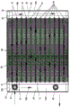
FIG. 1 is an exploded view of a first preferred embodiment of the present invention;
FIG. 2 is a top view of the first preferred embodiment of the present invention;
FIG. 3 is an exploded view of a second preferred embodiment of the present invention;
FIG. 4 is a top view of a second preferred embodiment of the present invention.
The attached drawings indicate the following:
10. splitter box 11 and first splitter water-stop sheet
12. First box body 13 and first box cover
101. Water inlet chamber 102 and transition chamber
103. Water outlet chamber 104, water inlet
105. Water outlet hole 106 and first mounting groove
107. Second mounting groove 108 and third mounting groove
20. Water collecting tank 21, second flow dividing water-stop sheet
22. Second box body 23, second box cover
201. First water collecting cavity 202 and second water collecting cavity
203. A fourth mounting groove 204 and a fifth mounting groove
205. Third water collecting cavity 206 and sixth mounting groove
31. First row of tubes 32, second row of tubes
33. Third bank of tubes 34, fourth bank of tubes
35. Fifth row of tubes 41, water inlet pipe joint
42. Water outlet pipe joint 50 and radiating fins
60. The fan fixed bolster.
Detailed Description
Referring to fig. 1 and 2, a detailed structure of a first preferred embodiment of the present invention is shown, which includes a diversion trench 10, a water collection trench 20, a first row of pipes 31, a second row of pipes 32, a third row of pipes 33, and a fourth row of pipes 34.
This splitter box 10 is the heat dissipation metal material, be provided with a plurality of first splitter water-stop sheets 11 in the splitter box 10 and separate the inside of splitter box 10 and be formed with intake chamber 101, transition cavity 102 and play water chamber 103, the inlet opening 104 has been seted up on this splitter box 10, apopore 105, first mounting groove 106, second mounting groove 107 and third mounting groove 108, this inlet opening 104 and first mounting groove 106 all communicate intake chamber 101, this apopore 105 and second mounting groove 107 all communicate play water chamber 103, this third mounting groove 108 intercommunication transition cavity 102. Specifically, the diversion trench 10 includes a first box body 12 and a first box cover 13, the first diversion water-stop sheet 11 is arranged in the first box body 12 by welding or integral molding, the first box cover 13 is fixed with the first box body 12 in a sealing manner and forms the water inlet cavity 101, the transition cavity 102 and the water outlet cavity 103 in an enclosing manner, the water inlet hole 104 and the water outlet hole 105 are both arranged on the first box body 12, the water inlet hole 104 is provided with the water inlet pipe joint 41 in a sealing manner, and the water outlet hole 105 is provided with the water outlet pipe joint 42 in a sealing manner; the first, second and third mounting grooves 106, 107 and 108 are formed in the first cover 13. And the water inlet pipe joint 41 is inserted into the water inlet hole 104 and is fixedly and hermetically mounted with the first box body 12 by welding, the water outlet pipe joint 42 is inserted into the water outlet hole 105 and is fixedly and hermetically mounted with the first box body 12 by welding, the first box body 12 and the first box cover 13 are made of copper or aluminum, and the first box cover 13 is fixedly and hermetically mounted with the first box body 12 by welding.
The water collection tank 20 is also made of heat dissipation metal, a plurality of second diversion water stop plates 21 are arranged in the water collection tank 20 to separate the inside of the water collection tank 20 into a first water collection chamber 201 and a second water collection chamber 202, a fourth installation groove 203 and a fifth installation groove 204 are formed in the water collection tank 20, the fourth installation groove 203 is communicated with the first water collection chamber 201, and the fifth installation groove 204 is communicated with the second water collection chamber 202. Specifically, the water collecting tank 20 includes a second box body 22 and a second box cover 23, the second diversion water-stop sheet 21 is disposed in the second box body 22 by welding or integral molding, and the second box cover 23 and the second box body 22 are sealed and fixed and form the first water collecting chamber 201 and the second water collecting chamber 202; the fourth mounting groove 203 and the fifth mounting groove 204 are both arranged on the second box cover 23; the second box 22 and the second box cover 23 are made of copper or aluminum, and the second box cover 23 is fixedly installed with the second box 22 in a sealing mode through welding.
The first row pipe 31, the second row pipe 32, the third row pipe 33 and the fourth row pipe 34 are all provided with radiating fins 50; in this embodiment, the first, second, third and fourth rows of tubes 31, 32, 33 and 34 are all heat dissipating metal flat tubes, but may be heat dissipating metal round tubes, and not limited thereto, and both ends of the first, second, third and fourth rows of tubes 31, 32, 33 and 34 are respectively welded and fixed to the diversion channel 10 and the water collection channel 20. Specifically, the method comprises the following steps:
one end of the first discharge pipe 31 is hermetically installed in the first installation groove 106 and communicated with the water inlet chamber 101, and the other end of the first discharge pipe 31 is hermetically installed in the corresponding fourth installation groove 203 and communicated with the first water collection chamber 201; in the present embodiment, the first exhaust pipes 31 are two pipes arranged side by side at intervals, which is not limited.
One end of the second row of tubes 32 is hermetically installed in the corresponding third installation groove 108 and communicated with the transition chamber 102, and the other end of the second row of tubes 32 is hermetically installed in the corresponding fourth installation groove 203 and communicated with the first water collection chamber 201; in the present embodiment, the second row of tubes 32 is two tubes that are arranged side by side at intervals, which is not limited.
One end of the third row of tubes 33 is hermetically installed in the third installation groove 108 and communicated with the transition chamber 102, and the other end of the third row of tubes 33 is hermetically installed in the corresponding fifth installation groove 204 and communicated with the second water collection chamber 202; in this embodiment, the third row of tubes 33 is two tubes arranged side by side at intervals, which is not limited.
One end of the fourth row of tubes 34 is hermetically installed in the second installation groove 107 and communicated with the water outlet chamber 103, and the other end of the fourth row of tubes 34 is hermetically installed in the corresponding fifth installation groove 204 and communicated with the second water collection chamber 202; in the present embodiment, the number of the fourth row pipes 34 is six, which are arranged side by side at intervals, but not limited thereto.
In addition, two fan fixing brackets 60 are connected between the diversion channel 10 and the water collection channel 20, the two fan fixing brackets 60 are arranged left and right, and the first discharge pipe 31, the second discharge pipe 32, the third discharge pipe 33 and the fourth discharge pipe 34 are arranged between the two fan fixing brackets 60, so that the whole structure of the product is more stable, and the fixed fans can be installed.
Detailed description the working principle of the present embodiment is as follows:
when the water heater is used, as shown in fig. 2, water with high temperature enters the water inlet cavity 101 from the water inlet pipe joint 41, then the water sequentially flows through the first discharge pipe 31, the first water collecting cavity 201, the second discharge pipe 32, the transition cavity 102, the third discharge pipe 33, the second water collecting cavity 202, the fourth discharge pipe 34 and the water outlet cavity 103, finally the water is output from the water outlet pipe joint 42, the temperature of the water is gradually reduced in the process of flowing through the water inlet cavity 101, the first discharge pipe 31, the first water collecting cavity 201, the second discharge pipe 32, the transition cavity 102, the third discharge pipe 33, the second water collecting cavity 202, the fourth discharge pipe 34 and the water outlet cavity 103, the temperature of the water output from the water outlet pipe joint 42 is low, and a good cooling and heat dissipation effect is achieved.
Referring to fig. 3 and fig. 4, a specific structure of a second preferred embodiment of the present invention is shown, which is basically the same as the specific structure of the first preferred embodiment, except that:
in this embodiment, there are two transition chambers 102, the two transition chambers 102 are located between the water inlet chamber 101 and the water outlet chamber 103, a third water collecting chamber 205 is formed in the water collecting tank 20, the third water collecting chamber 205 is located between the first water collecting chamber 201 and the second water collecting chamber 202, a sixth mounting groove 206 is formed on the water collecting tank 20, the sixth mounting groove 206 is communicated with the third water collecting chamber 205, each transition chamber 102 is communicated with the third water collecting chamber 205 through a fifth row of pipes 35, one end of each fifth row of pipes 35 is hermetically mounted in the corresponding third mounting groove 108, and the other end of each fifth row of pipes 35 is hermetically mounted in the corresponding sixth mounting groove 206, so that the stroke of water in the product can be extended, and a better cooling and heat dissipation effect can be achieved.
The operation principle of this embodiment is basically the same as that of the first preferred embodiment, and the operation principle of this embodiment will not be described in detail here.
The design of the invention is characterized in that: all be provided with the reposition of redundant personnel water-stop sheet and form a plurality of cavities through in diverging channel and water catch bowl to the cooperation sets up the corresponding cavity of each calandria intercommunication, makes the runner in this product be a plurality of circuitous structures that connect gradually, has effectively prolonged the flow stroke of water in the water-cooling is arranged, makes hydroenergy enough effectively fully cool down the heat dissipation, and the whole radiating effect of product is very good.
The above description is only a preferred embodiment of the present invention, and is not intended to limit the technical scope of the present invention, so that any minor modifications, equivalent changes and modifications made to the above embodiment according to the technical spirit of the present invention are within the technical scope of the present invention.
Claims (10)
1. The utility model provides a high-efficient heat dissipation water-cooling of multithread way formula is arranged which characterized in that: the device comprises a flow distribution groove, a water collection groove, a first calandria, a second calandria, a third calandria and a fourth calandria;
the splitter box is made of heat dissipation metal materials, a plurality of first splitter water-stop plates are arranged in the splitter box to divide the interior of the splitter box into a water inlet cavity, a transition cavity and a water outlet cavity, a water inlet hole, a water outlet hole, a first mounting groove, a second mounting groove and a third mounting groove are formed in the splitter box, the water inlet hole and the first mounting groove are communicated with the water inlet cavity, the water outlet hole and the second mounting groove are communicated with the water outlet cavity, and the third mounting groove is communicated with the transition cavity;
the water collecting tank is also made of heat dissipation metal materials, a plurality of second flow dividing water-stop plates are arranged in the water collecting tank to separate the interior of the water collecting tank into a first water collecting cavity and a second water collecting cavity, a fourth mounting groove and a fifth mounting groove are formed in the water collecting tank, the fourth mounting groove is communicated with the first water collecting cavity, and the fifth mounting groove is communicated with the second water collecting cavity;
the first, second, third and fourth rows of tubes are all provided with heat radiating fins; one end of the first calandria is hermetically arranged in the first mounting groove and communicated with the water inlet cavity, and the other end of the first calandria is hermetically arranged in the corresponding fourth mounting groove and communicated with the first water collecting cavity; one end of the second calandria is hermetically arranged in the corresponding third mounting groove and communicated with the transition chamber, and the other end of the second calandria is hermetically arranged in the corresponding fourth mounting groove and communicated with the first water collecting chamber; one end of the third calandria is hermetically arranged in the third mounting groove and communicated with the transition chamber, and the other end of the third calandria is hermetically arranged in the corresponding fifth mounting groove and communicated with the second water collecting chamber; one end of the fourth calandria is hermetically arranged in the second mounting groove and communicated with the water outlet cavity, and the other end of the fourth calandria is hermetically arranged in the corresponding fifth mounting groove and communicated with the second water collecting cavity.
2. The multi-channel high-efficiency heat-dissipation water-cooling bar according to claim 1, wherein: the transition cavity is two, two transition cavities are located into between the cavity and the play water cavity, be formed with the third cavity that catchments in this water catch bowl, the third cavity that catchments is located between first cavity and the second cavity that catchments, the sixth mounting groove has been seted up on this water catch bowl, this sixth mounting groove and the third cavity intercommunication that catchments, all communicate through the fifth calandria between each transition cavity and the third cavity that catchments, a tip seal installation of each fifth calandria is in the third mounting groove that corresponds, another tip seal installation of each fifth calandria is in the sixth mounting groove that corresponds.
3. The multi-channel high-efficiency heat-dissipation water-cooling bar according to claim 1, wherein: the splitter box comprises a first box body and a first box cover, the first splitter water-stop plate is arranged in the first box body in a welding or integrated forming mode, and the first box cover and the first box body are fixed in a sealing mode and form the water inlet cavity, the transition cavity and the water outlet cavity in a surrounding mode.
4. The multi-channel high-efficiency heat-dissipation water-cooling bar according to claim 3, wherein: the water inlet hole and the water outlet hole are both arranged on the first box body, a water inlet pipe connector is hermetically arranged in the water inlet hole, and a water outlet pipe connector is hermetically arranged in the water outlet hole; this first mounting groove, second mounting groove and third mounting groove all set up on first box cover.
5. The multi-channel high-efficiency heat-dissipation water-cooling bar according to claim 4, wherein: the water inlet pipe joint is inserted into the water inlet hole and is fixedly installed with the first box body in a sealing mode through welding, and the water outlet pipe joint is inserted into the water outlet hole and is fixedly installed with the first box body in a sealing mode through welding.
6. The multi-channel high-efficiency heat-dissipation water-cooling bar according to claim 3, wherein: first box body and first lid are copper or aluminium material, and this first lid is fixed through welding and first box body seal installation.
7. The multi-channel high-efficiency heat-dissipation water-cooling bar according to claim 1, wherein: the water collecting tank comprises a second box body and a second box cover, the second split water-stop sheet is arranged in the second box body in a welding or integrated forming mode, and the second box cover and the second box body are fixed in a sealing mode and form the first water collecting cavity and the second water collecting cavity in a surrounding mode.
8. The multi-channel high-efficiency heat-dissipation water-cooling bar according to claim 7, wherein: and the fourth mounting groove and the fifth mounting groove are both arranged on the second box cover.
9. The multi-channel high-efficiency heat-dissipation water-cooling bar according to claim 7, wherein: the second box body and the second box cover are made of copper or aluminum, and the second box cover is fixedly installed with the second box body in a sealing mode through welding.
10. The multi-channel high-efficiency heat-dissipation water-cooling bar according to claim 1, wherein: two fan fixing supports are connected between the flow dividing groove and the water collecting groove, the two fan fixing supports are arranged on the left and right sides, the first calandria, the second calandria, the third calandria and the fourth calandria are located between the two fan fixing supports, and the first calandria, the second calandria, the third calandria and the fourth calandria are heat dissipation metal flat tubes or heat dissipation metal round tubes.
Priority Applications (5)
| Application Number | Priority Date | Filing Date | Title |
|---|---|---|---|
| CN202011417465.9A CN112414164A (en) | 2020-12-07 | 2020-12-07 | Multi-runner type efficient radiating water-cooling radiator |
| TW110104229A TWI790540B (en) | 2020-12-07 | 2021-02-04 | Multi-channel high-efficiency heat dissipation water cooling radiator |
| US17/170,901 US20220178627A1 (en) | 2020-12-07 | 2021-02-09 | Multi-channel high-efficiency heat dissipation water-cooling radiator |
| JP2021032541A JP7152796B2 (en) | 2020-12-07 | 2021-03-02 | water cooling radiator |
| DE102021105437.0A DE102021105437A1 (en) | 2020-12-07 | 2021-03-05 | HIGH EFFICIENCY MULTI-CHANNEL WATER-COOLING RADIATOR |
Applications Claiming Priority (1)
| Application Number | Priority Date | Filing Date | Title |
|---|---|---|---|
| CN202011417465.9A CN112414164A (en) | 2020-12-07 | 2020-12-07 | Multi-runner type efficient radiating water-cooling radiator |
Publications (1)
| Publication Number | Publication Date |
|---|---|
| CN112414164A true CN112414164A (en) | 2021-02-26 |
Family
ID=74775781
Family Applications (1)
| Application Number | Title | Priority Date | Filing Date |
|---|---|---|---|
| CN202011417465.9A Pending CN112414164A (en) | 2020-12-07 | 2020-12-07 | Multi-runner type efficient radiating water-cooling radiator |
Country Status (5)
| Country | Link |
|---|---|
| US (1) | US20220178627A1 (en) |
| JP (1) | JP7152796B2 (en) |
| CN (1) | CN112414164A (en) |
| DE (1) | DE102021105437A1 (en) |
| TW (1) | TWI790540B (en) |
Cited By (1)
| Publication number | Priority date | Publication date | Assignee | Title |
|---|---|---|---|---|
| CN116618619A (en) * | 2023-07-06 | 2023-08-22 | 山西昌鸿电力器材有限公司 | Cooling device for hardware casting mold |
Families Citing this family (5)
| Publication number | Priority date | Publication date | Assignee | Title |
|---|---|---|---|---|
| CN113686174A (en) * | 2021-08-31 | 2021-11-23 | 上海马勒热系统有限公司 | Integrated radiator |
| TWI807461B (en) * | 2021-10-25 | 2023-07-01 | 奇鋐科技股份有限公司 | Liquid cooling device |
| CN114383435B (en) * | 2021-12-27 | 2023-08-29 | 江西鑫田车业有限公司 | Reinforcing plate for automobile radiator and automobile radiator |
| CN116408647B (en) * | 2023-04-23 | 2023-11-14 | 浙江亚美力新能源科技有限公司 | Automatic assembly system and method for automobile radiator core |
| CN116576011B (en) * | 2023-05-16 | 2023-10-17 | 江苏科力普汽车部件有限公司 | Radiator for tractor |
Family Cites Families (9)
| Publication number | Priority date | Publication date | Assignee | Title |
|---|---|---|---|---|
| DE102006016839A1 (en) | 2006-04-07 | 2007-10-11 | Att Automotivethermotech Gmbh | High performance heat exchanger e.g. for motor vehicles, exchanges heat between fluid having strong temperature dependence of viscosity and second fluid flowing separately |
| TWM386486U (en) * | 2006-11-06 | 2010-08-11 | Bo-Yong Zeng | Soldering type copper-aluminum heat dissipation device |
| TWM328022U (en) * | 2007-07-10 | 2008-03-01 | Golden Sun News Tech Co Ltd | Water-cooled heat exchanger and a heat dissipation device having the same |
| JP5618368B2 (en) | 2010-12-01 | 2014-11-05 | シャープ株式会社 | Heat exchanger and integrated air conditioner equipped with the same |
| JP6354198B2 (en) | 2014-02-21 | 2018-07-11 | いすゞ自動車株式会社 | Radiator |
| US9818671B2 (en) | 2015-02-10 | 2017-11-14 | Dynatron Corporation | Liquid-cooled heat sink for electronic devices |
| JP6922645B2 (en) * | 2017-10-20 | 2021-08-18 | 株式会社デンソー | Heat exchanger |
| CN110207507B (en) * | 2019-06-19 | 2020-07-17 | 中国船舶科学研究中心(中国船舶重工集团公司第七0二研究所) | Heat exchanger between board suitable for equipment under water |
| TWM591156U (en) * | 2019-12-05 | 2020-02-21 | 大陸商深圳市研派科技有限公司 | High efficiency liquid cooling heat dissipation system |
-
2020
- 2020-12-07 CN CN202011417465.9A patent/CN112414164A/en active Pending
-
2021
- 2021-02-04 TW TW110104229A patent/TWI790540B/en active
- 2021-02-09 US US17/170,901 patent/US20220178627A1/en not_active Abandoned
- 2021-03-02 JP JP2021032541A patent/JP7152796B2/en active Active
- 2021-03-05 DE DE102021105437.0A patent/DE102021105437A1/en active Pending
Cited By (1)
| Publication number | Priority date | Publication date | Assignee | Title |
|---|---|---|---|---|
| CN116618619A (en) * | 2023-07-06 | 2023-08-22 | 山西昌鸿电力器材有限公司 | Cooling device for hardware casting mold |
Also Published As
| Publication number | Publication date |
|---|---|
| TWI790540B (en) | 2023-01-21 |
| TW202127995A (en) | 2021-07-16 |
| DE102021105437A1 (en) | 2022-06-09 |
| JP7152796B2 (en) | 2022-10-13 |
| US20220178627A1 (en) | 2022-06-09 |
| JP2022090592A (en) | 2022-06-17 |
Similar Documents
| Publication | Publication Date | Title |
|---|---|---|
| CN112414164A (en) | Multi-runner type efficient radiating water-cooling radiator | |
| CN112393626A (en) | Liquid cooling radiating water discharge of water inlet multi-runner multi-water collecting box water adding pump | |
| CN112444050A (en) | Integral cavity type water cooling drainage with built-in water pump | |
| CN201340778Y (en) | Aluminum alloy radiator for power transformer | |
| CN112930098A (en) | Integrated liquid cooling radiator | |
| CN108766946B (en) | Liquid cooling heat abstractor and motor controller | |
| WO2019154083A1 (en) | Liquid cooling pipeline and power supply apparatus | |
| CN214407068U (en) | Multi-runner type efficient radiating water-cooling radiator | |
| CN111799238A (en) | Double-sided water-cooling IGBT radiator and radiating installation structure thereof | |
| CN116931698A (en) | Integrated liquid cooling radiator | |
| CN214708446U (en) | Integrated liquid cooling radiator | |
| CN214407066U (en) | Liquid cooling radiating water discharge of water inlet multi-runner multi-water collecting box water adding pump | |
| CN113593616A (en) | Heat dissipation device for memory | |
| CN109037833B (en) | Energy-saving battery radiator for electric automobile | |
| CN215113450U (en) | Integral cavity type water cooling drainage with built-in water pump | |
| CN210432318U (en) | Temperature control device of new energy automobile controller | |
| CN215810395U (en) | Improved liquid collecting tank and multi-runner liquid cooling bar | |
| CN116520964B (en) | Liquid cooling row and liquid cooling heat abstractor of two liquid pumps | |
| CN212727288U (en) | Convergence switch | |
| CN220292472U (en) | Water air conditioner control box heat radiation structure and water air conditioner control box thereof | |
| CN218784034U (en) | Heat abstractor for OTN optical transmission equipment | |
| CN210129505U (en) | Semiconductor heat radiation structure | |
| CN216744568U (en) | Novel water tank radiator | |
| CN219572283U (en) | High-efficient radiating water-cooling heat exchanger | |
| CN216620730U (en) | Adjustable aluminum radiator |
Legal Events
| Date | Code | Title | Description |
|---|---|---|---|
| PB01 | Publication | ||
| PB01 | Publication | ||
| SE01 | Entry into force of request for substantive examination | ||
| SE01 | Entry into force of request for substantive examination |