JP6922645B2 - Heat exchanger - Google Patents
Heat exchanger Download PDFInfo
- Publication number
- JP6922645B2 JP6922645B2 JP2017203360A JP2017203360A JP6922645B2 JP 6922645 B2 JP6922645 B2 JP 6922645B2 JP 2017203360 A JP2017203360 A JP 2017203360A JP 2017203360 A JP2017203360 A JP 2017203360A JP 6922645 B2 JP6922645 B2 JP 6922645B2
- Authority
- JP
- Japan
- Prior art keywords
- cooling water
- tank chamber
- tube
- heat exchanger
- inflow pipe
- Prior art date
- Legal status (The legal status is an assumption and is not a legal conclusion. Google has not performed a legal analysis and makes no representation as to the accuracy of the status listed.)
- Active
Links
Images


Classifications
-
- F—MECHANICAL ENGINEERING; LIGHTING; HEATING; WEAPONS; BLASTING
- F28—HEAT EXCHANGE IN GENERAL
- F28D—HEAT-EXCHANGE APPARATUS, NOT PROVIDED FOR IN ANOTHER SUBCLASS, IN WHICH THE HEAT-EXCHANGE MEDIA DO NOT COME INTO DIRECT CONTACT
- F28D1/00—Heat-exchange apparatus having stationary conduit assemblies for one heat-exchange medium only, the media being in contact with different sides of the conduit wall, in which the other heat-exchange medium is a large body of fluid, e.g. domestic or motor car radiators
- F28D1/02—Heat-exchange apparatus having stationary conduit assemblies for one heat-exchange medium only, the media being in contact with different sides of the conduit wall, in which the other heat-exchange medium is a large body of fluid, e.g. domestic or motor car radiators with heat-exchange conduits immersed in the body of fluid
- F28D1/04—Heat-exchange apparatus having stationary conduit assemblies for one heat-exchange medium only, the media being in contact with different sides of the conduit wall, in which the other heat-exchange medium is a large body of fluid, e.g. domestic or motor car radiators with heat-exchange conduits immersed in the body of fluid with tubular conduits
- F28D1/053—Heat-exchange apparatus having stationary conduit assemblies for one heat-exchange medium only, the media being in contact with different sides of the conduit wall, in which the other heat-exchange medium is a large body of fluid, e.g. domestic or motor car radiators with heat-exchange conduits immersed in the body of fluid with tubular conduits the conduits being straight
- F28D1/0535—Heat-exchange apparatus having stationary conduit assemblies for one heat-exchange medium only, the media being in contact with different sides of the conduit wall, in which the other heat-exchange medium is a large body of fluid, e.g. domestic or motor car radiators with heat-exchange conduits immersed in the body of fluid with tubular conduits the conduits being straight the conduits having a non-circular cross-section
- F28D1/05358—Assemblies of conduits connected side by side or with individual headers, e.g. section type radiators
-
- F—MECHANICAL ENGINEERING; LIGHTING; HEATING; WEAPONS; BLASTING
- F01—MACHINES OR ENGINES IN GENERAL; ENGINE PLANTS IN GENERAL; STEAM ENGINES
- F01P—COOLING OF MACHINES OR ENGINES IN GENERAL; COOLING OF INTERNAL-COMBUSTION ENGINES
- F01P3/00—Liquid cooling
- F01P3/12—Arrangements for cooling other engine or machine parts
-
- F—MECHANICAL ENGINEERING; LIGHTING; HEATING; WEAPONS; BLASTING
- F01—MACHINES OR ENGINES IN GENERAL; ENGINE PLANTS IN GENERAL; STEAM ENGINES
- F01P—COOLING OF MACHINES OR ENGINES IN GENERAL; COOLING OF INTERNAL-COMBUSTION ENGINES
- F01P3/00—Liquid cooling
- F01P3/18—Arrangements or mounting of liquid-to-air heat-exchangers
-
- F—MECHANICAL ENGINEERING; LIGHTING; HEATING; WEAPONS; BLASTING
- F28—HEAT EXCHANGE IN GENERAL
- F28D—HEAT-EXCHANGE APPARATUS, NOT PROVIDED FOR IN ANOTHER SUBCLASS, IN WHICH THE HEAT-EXCHANGE MEDIA DO NOT COME INTO DIRECT CONTACT
- F28D1/00—Heat-exchange apparatus having stationary conduit assemblies for one heat-exchange medium only, the media being in contact with different sides of the conduit wall, in which the other heat-exchange medium is a large body of fluid, e.g. domestic or motor car radiators
- F28D1/02—Heat-exchange apparatus having stationary conduit assemblies for one heat-exchange medium only, the media being in contact with different sides of the conduit wall, in which the other heat-exchange medium is a large body of fluid, e.g. domestic or motor car radiators with heat-exchange conduits immersed in the body of fluid
- F28D1/04—Heat-exchange apparatus having stationary conduit assemblies for one heat-exchange medium only, the media being in contact with different sides of the conduit wall, in which the other heat-exchange medium is a large body of fluid, e.g. domestic or motor car radiators with heat-exchange conduits immersed in the body of fluid with tubular conduits
- F28D1/053—Heat-exchange apparatus having stationary conduit assemblies for one heat-exchange medium only, the media being in contact with different sides of the conduit wall, in which the other heat-exchange medium is a large body of fluid, e.g. domestic or motor car radiators with heat-exchange conduits immersed in the body of fluid with tubular conduits the conduits being straight
- F28D1/0535—Heat-exchange apparatus having stationary conduit assemblies for one heat-exchange medium only, the media being in contact with different sides of the conduit wall, in which the other heat-exchange medium is a large body of fluid, e.g. domestic or motor car radiators with heat-exchange conduits immersed in the body of fluid with tubular conduits the conduits being straight the conduits having a non-circular cross-section
- F28D1/05366—Assemblies of conduits connected to common headers, e.g. core type radiators
-
- F—MECHANICAL ENGINEERING; LIGHTING; HEATING; WEAPONS; BLASTING
- F28—HEAT EXCHANGE IN GENERAL
- F28F—DETAILS OF HEAT-EXCHANGE AND HEAT-TRANSFER APPARATUS, OF GENERAL APPLICATION
- F28F1/00—Tubular elements; Assemblies of tubular elements
- F28F1/10—Tubular elements and assemblies thereof with means for increasing heat-transfer area, e.g. with fins, with projections, with recesses
- F28F1/12—Tubular elements and assemblies thereof with means for increasing heat-transfer area, e.g. with fins, with projections, with recesses the means being only outside the tubular element
- F28F1/126—Tubular elements and assemblies thereof with means for increasing heat-transfer area, e.g. with fins, with projections, with recesses the means being only outside the tubular element consisting of zig-zag shaped fins
-
- F—MECHANICAL ENGINEERING; LIGHTING; HEATING; WEAPONS; BLASTING
- F28—HEAT EXCHANGE IN GENERAL
- F28F—DETAILS OF HEAT-EXCHANGE AND HEAT-TRANSFER APPARATUS, OF GENERAL APPLICATION
- F28F9/00—Casings; Header boxes; Auxiliary supports for elements; Auxiliary members within casings
- F28F9/02—Header boxes; End plates
- F28F9/0202—Header boxes having their inner space divided by partitions
-
- F—MECHANICAL ENGINEERING; LIGHTING; HEATING; WEAPONS; BLASTING
- F28—HEAT EXCHANGE IN GENERAL
- F28F—DETAILS OF HEAT-EXCHANGE AND HEAT-TRANSFER APPARATUS, OF GENERAL APPLICATION
- F28F9/00—Casings; Header boxes; Auxiliary supports for elements; Auxiliary members within casings
- F28F9/02—Header boxes; End plates
- F28F9/0246—Arrangements for connecting header boxes with flow lines
-
- F—MECHANICAL ENGINEERING; LIGHTING; HEATING; WEAPONS; BLASTING
- F28—HEAT EXCHANGE IN GENERAL
- F28D—HEAT-EXCHANGE APPARATUS, NOT PROVIDED FOR IN ANOTHER SUBCLASS, IN WHICH THE HEAT-EXCHANGE MEDIA DO NOT COME INTO DIRECT CONTACT
- F28D21/00—Heat-exchange apparatus not covered by any of the groups F28D1/00 - F28D20/00
- F28D2021/0019—Other heat exchangers for particular applications; Heat exchange systems not otherwise provided for
- F28D2021/0028—Other heat exchangers for particular applications; Heat exchange systems not otherwise provided for for cooling heat generating elements, e.g. for cooling electronic components or electric devices
- F28D2021/0031—Radiators for recooling a coolant of cooling systems
-
- F—MECHANICAL ENGINEERING; LIGHTING; HEATING; WEAPONS; BLASTING
- F28—HEAT EXCHANGE IN GENERAL
- F28D—HEAT-EXCHANGE APPARATUS, NOT PROVIDED FOR IN ANOTHER SUBCLASS, IN WHICH THE HEAT-EXCHANGE MEDIA DO NOT COME INTO DIRECT CONTACT
- F28D21/00—Heat-exchange apparatus not covered by any of the groups F28D1/00 - F28D20/00
- F28D2021/0019—Other heat exchangers for particular applications; Heat exchange systems not otherwise provided for
- F28D2021/008—Other heat exchangers for particular applications; Heat exchange systems not otherwise provided for for vehicles
- F28D2021/0091—Radiators
- F28D2021/0094—Radiators for recooling the engine coolant
-
- F—MECHANICAL ENGINEERING; LIGHTING; HEATING; WEAPONS; BLASTING
- F28—HEAT EXCHANGE IN GENERAL
- F28F—DETAILS OF HEAT-EXCHANGE AND HEAT-TRANSFER APPARATUS, OF GENERAL APPLICATION
- F28F9/00—Casings; Header boxes; Auxiliary supports for elements; Auxiliary members within casings
- F28F9/02—Header boxes; End plates
- F28F2009/0285—Other particular headers or end plates
- F28F2009/0287—Other particular headers or end plates having passages for different heat exchange media
-
- F—MECHANICAL ENGINEERING; LIGHTING; HEATING; WEAPONS; BLASTING
- F28—HEAT EXCHANGE IN GENERAL
- F28F—DETAILS OF HEAT-EXCHANGE AND HEAT-TRANSFER APPARATUS, OF GENERAL APPLICATION
- F28F2210/00—Heat exchange conduits
- F28F2210/04—Arrangements of conduits common to different heat exchange sections, the conduits having channels for different circuits
-
- F—MECHANICAL ENGINEERING; LIGHTING; HEATING; WEAPONS; BLASTING
- F28—HEAT EXCHANGE IN GENERAL
- F28F—DETAILS OF HEAT-EXCHANGE AND HEAT-TRANSFER APPARATUS, OF GENERAL APPLICATION
- F28F2270/00—Thermal insulation; Thermal decoupling
- F28F2270/02—Thermal insulation; Thermal decoupling by using blind conduits
-
- F—MECHANICAL ENGINEERING; LIGHTING; HEATING; WEAPONS; BLASTING
- F28—HEAT EXCHANGE IN GENERAL
- F28F—DETAILS OF HEAT-EXCHANGE AND HEAT-TRANSFER APPARATUS, OF GENERAL APPLICATION
- F28F9/00—Casings; Header boxes; Auxiliary supports for elements; Auxiliary members within casings
- F28F9/02—Header boxes; End plates
- F28F9/0202—Header boxes having their inner space divided by partitions
- F28F9/0204—Header boxes having their inner space divided by partitions for elongated header box, e.g. with transversal and longitudinal partitions
-
- F—MECHANICAL ENGINEERING; LIGHTING; HEATING; WEAPONS; BLASTING
- F28—HEAT EXCHANGE IN GENERAL
- F28F—DETAILS OF HEAT-EXCHANGE AND HEAT-TRANSFER APPARATUS, OF GENERAL APPLICATION
- F28F9/00—Casings; Header boxes; Auxiliary supports for elements; Auxiliary members within casings
- F28F9/26—Arrangements for connecting different sections of heat-exchange elements, e.g. of radiators
Description
本開示は、熱交換器に関する。 The present disclosure relates to heat exchangers.
ハイブリッド車やプラグインハイブリッド車等、エンジンと電動機の2つの動力源を有する車両では、通常、エンジンを冷却するためのラジエータと、インバータ等の電気系を冷却するためのラジエータとが必要となる。しかしながら、2つのラジエータを配列すると、通風抵抗の増加や、冷却風の温度の上昇に起因するラジエータの放熱性能の低下等を招くおそれがある。そこで、従来、2つの冷却回路を有する熱交換器が提案されている。このような熱交換器としては、例えば下記特許文献1に記載の熱交換器がある。 A vehicle having two power sources, an engine and an electric motor, such as a hybrid vehicle and a plug-in hybrid vehicle, usually requires a radiator for cooling the engine and a radiator for cooling an electric system such as an inverter. However, if the two radiators are arranged, there is a risk that the ventilation resistance will increase and the heat dissipation performance of the radiators will deteriorate due to the rise in the temperature of the cooling air. Therefore, conventionally, a heat exchanger having two cooling circuits has been proposed. Examples of such a heat exchanger include the heat exchanger described in Patent Document 1 below.
特許文献1に記載の熱交換器は、複数のチューブを有するコア部と、コア部の両端部にそれぞれ配置される一対のヘッダタンクとを備えている。ヘッダタンクは、その内部空間を第1タンク室と第2タンク室とに区画する仕切壁を有している。第1タンク室、及び第1タンク室に接続されるコア部のチューブは第1冷却回路を構成しており、エンジン冷却水が流れる部分となっている。第2タンク室、及び第2タンク室に接続されるコア部のチューブは第2冷却回路を構成しており、電気系の冷却水が流れる部分となっている。また、第1タンク室には、仕切壁による境界部から少なくとも一本のチューブに供給されるエンジン冷却水の流量を低減するための遮蔽板が設けられている。この遮蔽板により、第1冷却回路と第2冷却回路との境界部に供給される冷却水の流量が低減するため、第1冷却回路と第2冷却回路をそれぞれ流れる冷却水の温度差に起因して発生する境界部の熱歪みを抑制することが可能となっている。 The heat exchanger described in Patent Document 1 includes a core portion having a plurality of tubes and a pair of header tanks arranged at both ends of the core portion. The header tank has a partition wall that divides the internal space into a first tank chamber and a second tank chamber. The tube of the core portion connected to the first tank chamber and the first tank chamber constitutes the first cooling circuit, and is a portion through which the engine cooling water flows. The tube of the core portion connected to the second tank chamber and the second tank chamber constitutes the second cooling circuit, and is a portion through which the cooling water of the electric system flows. Further, the first tank chamber is provided with a shielding plate for reducing the flow rate of the engine cooling water supplied to at least one tube from the boundary portion formed by the partition wall. This shielding plate reduces the flow rate of the cooling water supplied to the boundary between the first cooling circuit and the second cooling circuit, which is caused by the temperature difference of the cooling water flowing through the first cooling circuit and the second cooling circuit, respectively. It is possible to suppress the thermal strain of the boundary portion generated as a result.
ところで、極低温化で車両が走行しているような場合には、エンジン冷却水の温度に比較して電気系の冷却水の温度が大幅に低くなる。このような状況下では、第1冷却回路と第2冷却回路をそれぞれ流れる冷却水の温度差が大きくなるため、特許文献1に記載の熱交換器のように第1タンク室に遮蔽板を設けた場合でも、コア部の熱歪みを十分に抑制することができない可能性がある。 By the way, when the vehicle is running at an extremely low temperature, the temperature of the cooling water of the electric system is significantly lower than the temperature of the cooling water of the engine. Under such a situation, the temperature difference between the cooling water flowing through the first cooling circuit and the second cooling circuit becomes large. Therefore, a shielding plate is provided in the first tank chamber as in the heat exchanger described in Patent Document 1. Even in such a case, there is a possibility that the thermal strain of the core portion cannot be sufficiently suppressed.
本開示は、こうした実情に鑑みてなされたものであり、その目的は、温度の異なる2種類の流体が流れる構造で有りながら、それらの温度差に起因して発生するコア部の熱歪みをより的確に抑制することの可能な熱交換器を提供することにある。 The present disclosure has been made in view of such circumstances, and the purpose of the present disclosure is to improve the thermal strain of the core portion generated due to the temperature difference between the two types of fluids having different temperatures, even though the structure is such that the two types of fluids flow. The purpose is to provide a heat exchanger that can be accurately suppressed.
上記課題を解決する熱交換器(HE)は、複数のチューブ(31)が積層されて構成されるコア部(30)と、複数のチューブの長手方向の端部に設けられ、複数のチューブに連通されるヘッダタンク(10)と、を備える。ヘッダタンクは、その内部通路を第1タンク室(121)及び第2タンク室(122)に区画する仕切部(130)と、第1流体を第1タンク室に流入させる第1流入パイプ(141)と、第1流体とは温度帯の異なる第2流体を第2タンク室に流入させる第2流入パイプ(142)と、を有する。第1タンク室において仕切部が設けられる一端部からその反対側の他端部に向かう方向を所定方向とするとき、第1流入パイプは、第1流入パイプから第1タンク室に流入する第1流体の流れ方向が所定方向の成分を有する方向となるようにヘッダタンクの外面に対して直角とは異なる角度で傾斜している。 The heat exchanger (HE) that solves the above problems is provided at the core portion (30) formed by laminating a plurality of tubes (31) and at the end portions in the longitudinal direction of the plurality of tubes, and is provided in the plurality of tubes. A header tank (10) to be communicated with is provided. The header tank has a partition (130) that divides the internal passage into the first tank chamber (121) and the second tank chamber (122), and a first inflow pipe (141) that allows the first fluid to flow into the first tank chamber. ) And a second inflow pipe (142) that allows a second fluid having a temperature zone different from that of the first fluid to flow into the second tank chamber. When the direction from one end where the partition is provided in the first tank chamber to the other end on the opposite side is a predetermined direction, the first inflow pipe flows into the first tank chamber from the first inflow pipe. The fluid is inclined at an angle different from the right angle with respect to the outer surface of the header tank so that the flow direction of the fluid has a component in a predetermined direction.
この構成によれば、第1流入パイプから第1タンク室に流入する第1流体が、所定方向に、すなわち第1タンク室の仕切部から離間する方向に流れ易くなる。よって、第1タンク室では、仕切部に向かって第1冷却水が流れ難くなる。また、コア部において仕切部に対応する部分は、第1流体が流れる冷却回路と、第2流体が流れる冷却回路との境界部分となる。そのため、第1冷却水が仕切部に向かって流れ難くなることにより、結果的にコア部の冷却回路境界部分付近のチューブに第1流体が流れ難くなる。このようにコア部の冷却回路境界部分付近のチューブに第1流体が流れ難くなることにより、コア部の冷却回路境界部分のチューブに第1流体及び第2流体の温度差に起因する熱勾配が発生し難くなる。よって、コア部に発生する熱歪みをより的確に抑制することができる。 According to this configuration, the first fluid flowing into the first tank chamber from the first inflow pipe tends to flow in a predetermined direction, that is, in a direction away from the partition portion of the first tank chamber. Therefore, in the first tank chamber, it becomes difficult for the first cooling water to flow toward the partition portion. Further, the portion of the core portion corresponding to the partition portion is a boundary portion between the cooling circuit through which the first fluid flows and the cooling circuit through which the second fluid flows. Therefore, it becomes difficult for the first cooling water to flow toward the partition portion, and as a result, it becomes difficult for the first fluid to flow to the tube near the boundary portion of the cooling circuit of the core portion. In this way, it becomes difficult for the first fluid to flow through the tube near the cooling circuit boundary portion of the core portion, so that the tube at the cooling circuit boundary portion of the core portion has a thermal gradient due to the temperature difference between the first fluid and the second fluid. It becomes difficult to occur. Therefore, the thermal strain generated in the core portion can be suppressed more accurately.
なお、上記手段、特許請求の範囲に記載の括弧内の符号は、後述する実施形態に記載の具体的手段との対応関係を示す一例である。 The reference numerals in parentheses described in the above means and claims are examples showing the correspondence with the specific means described in the embodiments described later.
本開示によれば、コア部の熱歪みをより的確に抑制することの可能な熱交換器を提供できる。 According to the present disclosure, it is possible to provide a heat exchanger capable of more accurately suppressing the thermal strain of the core portion.
以下、熱交換器の一実施形態について図面を参照しながら説明する。説明の理解を容易にするため、各図面において同一の構成要素に対しては可能な限り同一の符号を付して、重複する説明は省略する。
<第1実施形態>
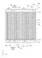
はじめに、図1及び図2を参照して、第1実施形態の熱交換器HEの構造について説明する。熱交換器HEは、ハイブリッド自動車等の車両に搭載されており、エンジンの冷却水のためのラジエータ、及びインバータ等の電気系の冷却水のためのラジエータとして機能する。本実施形態では、エンジン冷却水が第1流体に相当し、電気系の冷却水が第2流体に相当する。エンジン冷却水の温度は、通常、電気系冷却水の温度よりも高い。すなわち、熱交換器HEには、温度帯の異なる2種類の冷却水が流れている。
Hereinafter, an embodiment of the heat exchanger will be described with reference to the drawings. In order to facilitate understanding of the description, the same components are designated by the same reference numerals as much as possible in each drawing, and duplicate description is omitted.
<First Embodiment>
First, the structure of the heat exchanger HE of the first embodiment will be described with reference to FIGS. 1 and 2. The heat exchanger HE is mounted on a vehicle such as a hybrid vehicle, and functions as a radiator for cooling water of an engine and a radiator for cooling water of an electric system such as an inverter. In the present embodiment, the engine cooling water corresponds to the first fluid, and the electric system cooling water corresponds to the second fluid. The temperature of the engine cooling water is usually higher than the temperature of the electric system cooling water. That is, two types of cooling water having different temperature zones are flowing through the heat exchanger HE.
熱交換器HEは、上側ヘッダタンク10と、下側ヘッダタンク20と、コア部30とを備えている。一対のヘッダタンク10,20は、コア部30の両端部にそれぞれ配置されている。
コア部30は、その内部を流れる冷却水と空気との間で熱交換を行う部分である。コア部30は、複数のチューブ31と、複数のフィン32とを備えている。
The heat exchanger HE includes an
The
複数のチューブ31は、矢印Zで示される方向に長手方向を有する扁平状の細長い管である。チューブ31の内部通路は、車エンジン冷却水又は電気系冷却水が流れる通路となっている。複数のチューブ31は、図中に矢印Xで示される方向に所定の隙間を有して積層して配置されている。フィン32は、隣り合うチューブ31,31間の隙間に配置されている。フィン32は、薄く長い金属板をつづら折りに加工することにより形成された、いわゆるコルゲートフィンである。
The plurality of
コア部30では、図中に矢印Yで示される方向、すなわち矢印Xで示される方向及び矢印Zで示される方向の両方に直交する方向に空気が流れることにより、チューブ31,31間の隙間に空気が流れる。この空気と、チューブ31の内部を流れる冷却水との間で熱交換が行われることにより、チューブ31の内部を流れる冷却水が冷却される。フィン32は、伝熱面積を増やすことにより熱交換性能を高める機能を有している。
In the
なお、以下では、便宜上、矢印Xで示される方向を「チューブ積層方向X」とも称し、矢印Yで示される方向を「空気流れ方向Y」とも称し、矢印Zで示される方向を「チューブ長手方向Z」とも称する。なお、チューブ長手方向Zは、鉛直方向に平行な方向である。
上側ヘッダタンク10は、下側ヘッダタンク20よりも鉛直方向の上方に配置されている。上側ヘッダタンク10には、複数のチューブ31の上端部が接続されている。上側ヘッダタンク10は、エンジン冷却水及び電気系冷却水が流入するとともに、流入した冷却水を複数のチューブにそれぞれ分配する機能を有する部分である。上側ヘッダタンク10は、本体部100と、コアプレート110とを備えている。
In the following, for convenience, the direction indicated by the arrow X is also referred to as the “tube stacking direction X”, the direction indicated by the arrow Y is also referred to as the “air flow direction Y”, and the direction indicated by the arrow Z is referred to as the “tube longitudinal direction”. Also referred to as "Z". The tube longitudinal direction Z is a direction parallel to the vertical direction.
The
本体部100は、その一面が開口された箱状の部材である。本体部100の開口された一面には、コアプレート110が接合されている。より詳しくは、コアプレート110に形成された爪が折り曲げられて本体部100に形成されたフランジにかしめられることにより、本体部100にコアプレート110が接合されている。本体部100の内壁及びコアプレート110によって囲まれる空間により、上側ヘッダタンク10の内部通路120が形成されている。なお、図中の符号101は、本体部100において空気流れ方向Yの上流側に配置される外面を示している。
The
本体部100には、上側ヘッダタンク10の内部通路120を第1タンク室121及び第2タンク室122に区画する仕切部130が形成されている。本実施形態では、仕切部130が第1仕切部に相当する。第1タンク室121及び第2タンク室122は、一方のタンク室を流れる冷却水が他方のタンク室に流れ込まない独立した空間となっている。第1タンク室121は、第2タンク室122よりも大きい。
The
なお、図中の矢印X1で示される方向は、第1タンク室121において仕切部130が設けられる一端部からその反対側の他端部に向かう方向を示している。また、図中の矢印X2は、第2タンク室122において仕切部130が設けられる一端部からその反対側の他端部に向かう方向を示している。矢印X1,X2で示される方向は共にチューブ積層方向Xに平行な方向である。本実施形態では、矢印X1で示される方向が第1所定方向に相当し、矢印X2で示される方向が第2所定方向に相当する。
The direction indicated by the arrow X1 in the drawing indicates a direction from one end of the
コアプレート110には、複数のチューブ31の上端部が挿入されて接合されている。これにより、第1タンク室121及び第2タンク室122のそれぞれと複数のチューブ31の内部通路とが連通されている。以下では、複数のチューブ31のうち、第1タンク室121に連通されるチューブを第1チューブ311と称し、第2タンク室122に連通されるチューブを第2チューブ312と称する。
The upper ends of the plurality of
複数のチューブ31には、第1チューブ311と第2チューブ312との間に配置されるダミーチューブ310が含まれている。ダミーチューブ310は、上側ヘッダタンク10の仕切部130に対応する部分に配置されているチューブである。換言すれば、ダミーチューブ310は、第1タンク室121及び第2タンク室122のいずれにも連通されていないチューブである。すなわち、ダミーチューブ310は、第1チューブ311及び第2チューブ312とは異なり、冷却水の流れないチューブである。
The plurality of
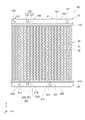
本体部100の外面101には、第1流入パイプ141及び第2流入パイプ142が形成されている。
第1流入パイプ141は、本体部100において第1タンク室121が形成されている部分であって、且つ仕切部130から所定方向X1に所定距離だけずれた位置に設けられている。図2に示されるように、第1流入パイプ141の中心軸m1は、本体部100の外面101に対して直角とは異なる角度で傾斜している。また、第1流入パイプ141は、空気流れ方向Yの上流側に向かって延びるように形成されている。第1流入パイプ141は、その本体部100に接続される一端部131aが他端部131bよりも矢印X1で示される方向にずれて位置するように形成されている。第1流入パイプ141には、エンジン冷却水が流入する。第1流入パイプ141に流入したエンジン冷却水は、第1タンク室121に流入するとともに、第1タンク室121から第1チューブ311に分配される。
A
The
第2流入パイプ142は、本体部100において第2タンク室122が形成されている部分であって、且つ仕切部130から所定方向X2に所定距離だけずれた位置に設けられている。第2流入パイプ142は、空気流れ方向Yに平行に空気流れ方向Yの上流側に向かって延びるように形成されている。第2流入パイプ142には、電気系冷却水が流入する。第2流入パイプ142に流入した電気系冷却水は、第2タンク室122に流入するとともに、第2タンク室122から第2チューブ312に分配される。
The
図1に示されるように、下側ヘッダタンク20には、複数のチューブ31の下端部が接続されている。下側ヘッダタンク20は、複数のチューブ31を流れた冷却水が流入するとともに、流入する冷却水を集合させて流出させる機能を有する部分である。下側ヘッダタンク20も、上側ヘッダタンク10と同様に、本体部200と、コアプレート210とを備えている。なお、下側ヘッダタンク20の構造は上側ヘッダタンク10の構造と類似しているため、下側ヘッダタンク20の構造については上側ヘッダタンク10と異なる部分を中心に説明する。
As shown in FIG. 1, the
下側ヘッダタンク20の本体部200には、下側ヘッダタンク20の内部通路220を第3タンク室221及び第4タンク室222に区画する仕切部230が形成されている。本実施形態では、仕切部230が第2仕切部に相当する。仕切部230は、チューブ長手方向Zにおいて、上側ヘッダタンク10の仕切部130に対応する位置に設けられている。第3タンク室221は、上側ヘッダタンク10の第1タンク室121に対応する位置に設けられている。第3タンク室221は、第1チューブ311を通じて第1タンク室121に連通されている。第4タンク室222は、上側ヘッダタンク10の第2タンク室122に対応する位置に設けられている。第4タンク室222は、第2チューブ312を通じて第2タンク室122に連通されている。なお、ダミーチューブ310は、第3タンク室221及び第4タンク室222のいずれにも連通されていない。
The
本体部200の外面201には、第1流出パイプ241及び第2流出パイプ242が形成されている。
第1流出パイプ241は、本体部200において第3タンク室221が形成されている部分であって、且つ第3タンク室221の略中央に設けられている。下側ヘッダタンク20では、第1チューブ311を流れたエンジン冷却水が第3タンク室221に集められるとともに、この第3タンク室221に集められた冷却水が第1流出パイプ241から流出する。
A
The
第2流出パイプ242は、本体部200において第4タンク室222が形成されている部分であって、且つ第4タンク室222の略中央に設けられている。下側ヘッダタンク20では、第2チューブ312を流れた電気系冷却水が第4タンク室222に集められるとともに、この第4タンク室222に集められた冷却水が第2流出パイプ242から流出する。
The
次に、本実施形態の熱交換器HEの動作例について説明する。
本実施形態の熱交換器HEでは、第1流入パイプ141から上側ヘッダタンク10の第1タンク室121に流入するエンジン冷却水が第1チューブ311に分配される。第1チューブ311をエンジン冷却水が流れる際、第1チューブ311の外周を流れる空気とエンジン冷却水との間で熱交換が行われることにより、エンジン冷却水が冷却される。この冷却されたエンジン冷却水が第1チューブ311を通じて下側ヘッダタンク20の第3タンク室221に集められた後、第1流出パイプ241から流出する。
Next, an operation example of the heat exchanger HE of the present embodiment will be described.
In the heat exchanger HE of the present embodiment, the engine cooling water flowing from the
また、熱交換器HEでは、第2流入パイプ142から上側ヘッダタンク10の第2タンク室122に流入する電気系冷却水が第2チューブ312に分配される。第2チューブ312を電気系冷却水が流れる際、第2チューブ312の外周を流れる空気と電気系冷却水との間で熱交換が行われることにより、電気系冷却水が冷却される。この冷却された電気系冷却水が第2チューブ312を通じて下側ヘッダタンク20の第4タンク室222に集められた後、第2流出パイプ242から流出する。
Further, in the heat exchanger HE, the electric cooling water flowing from the
また、熱交換器HEでは、エンジン冷却水が流れる第1チューブ311と、電気系冷却水が流れる第2チューブ312との間に温度差が生じるため、それらの境界部分に熱歪みが生じ易い。この点、熱交換器HEには、コア部30の第1チューブ311と第2チューブ312との間にダミーチューブ310が設けられているため、第1チューブ311と第2チューブ312との間に生じる熱歪みを抑制することが可能となっている。
Further, in the heat exchanger HE, since a temperature difference occurs between the
ところで、熱交換器HEにダミーチューブ310が設けられている場合でも、例えば極低温化など、エンジン冷却水と電気系冷却水とに大きな温度差が生じやすい状況では、ダミーチューブ310による熱歪みの抑制効果が低下する可能性がある。これが、コア部30においてエンジン冷却水の流れる冷却回路と電気系冷却水の流れる冷却回路との境界部分、すなわちダミーチューブ310近傍の部分に熱歪みを発生させる要因となる。
By the way, even when the
この点、本実施形態の熱交換器HEでは、第1流入パイプ141が図2に示されるように形成されているため、第1流入パイプ141から第1タンク室121にエンジン冷却水が流入する際、この冷却水の流れ方向は図中の拡大図に示される矢印L1方向となる。すなわち、冷却水の流れ方向L1は、空気の流れ方向Yに平行な方向の成分L10だけでなく、所定方向X1の成分も有する方向となる。結果的に、第1流入パイプ141から第1タンク室121に流入する冷却水は、所定方向X1に流れ易くなる、すなわち仕切部130から離間する方向に流れ易くなる。よって、第1タンク室121では、仕切部130に向かってエンジン冷却水が流れ難くなる。
In this regard, in the heat exchanger HE of the present embodiment, since the
また、コア部30において仕切部130に対応する部分には、ダミーチューブ310が配置されている。そのため、エンジン冷却水が第1タンク室121の仕切部130に向かって流れ難くなることにより、結果的にダミーチューブ310付近の第1チューブ311にエンジン冷却水が流れ難くなる。
Further, a
このようにコア部30のダミーチューブ310付近の第1チューブ311にエンジン冷却水が流れ難くなることにより、ダミーチューブ310近傍の部分にエンジン冷却水及び電気系冷却水の温度差に起因する温度勾配が発生し難くなる。よって、コア部30に発生する熱歪みをより的確に抑制することができる。
As described above, it becomes difficult for the engine cooling water to flow to the
以上説明した本実施形態の熱交換器HEによれば、以下の(1)及び(2)に示される作用及び効果を得ることができる。
(1)第1流入パイプ141は、第1流入パイプ141から第1タンク室121に流入するエンジン冷却水の流れ方向が所定方向X1の成分を有する方向となるように上側ヘッダタンク10の外面101に対して直角とは異なる角度で傾斜している。これにより、エンジン冷却水及び電気系冷却水の温度差に起因してコア部30に発生する熱歪みをより的確に抑制することができる。
According to the heat exchanger HE of the present embodiment described above, the actions and effects shown in the following (1) and (2) can be obtained.
(1) The
さらに、このような構造によれば、第1流入パイプ141から第1タンク室121にエンジン冷却水が流入する際に、エンジン冷却水に作用する通水抵抗を低減することができる。また、エンジン冷却水が、第1タンク室121の仕切部130とは反対側の端部まで流れ易くなるため、第1チューブ311の全体にエンジン冷却水を流すことができる。これにより、熱交換器HEの放熱性能の低下を抑制することもできる。
Further, according to such a structure, when the engine cooling water flows from the
(2)電気系冷却水よりも高温のエンジン冷却水が流入する第1タンク室121の第1流入パイプ141を図1及び図2に示されるように形成することにより、コア部30のダミーチューブ310近傍の部分に、エンジン冷却水及び電気系冷却水の温度差に起因する温度勾配を更に発生し難くすることができる。よって、コア部30に発生する熱歪みを更に的確に抑制することができる。
(2) By forming the
(変形例)
次に、第1実施形態の熱交換器HEの変形例について説明する。
図3に示されるように、本変形例の熱交換器HEでは、第1流入パイプ141の中心軸m2が、上側ヘッダタンク10の外面101に対して直角とは異なる角度で傾斜している。これにより、第2流入パイプ142から第2タンク室122に流入する電気系冷却水の流れ方向が所定方向X2の成分を有する方向となる。すなわち、第2流入パイプ142は、第2流入パイプ142から第2タンク室122に流入する電気系冷却水の流れ方向が所定方向X2の成分を有する方向となるように上側ヘッダタンク10の外面101に対して直角とは異なる角度で傾斜している。このような構造により、第2タンク室122において、電気系冷却水がコア部30のダミーチューブ310付近の第2チューブ312に流れ難くなる。これにより、コア部30のダミーチューブ310近傍の部分にエンジン冷却水及び電気系冷却水の温度差に起因する温度勾配が更に発生し難くなるため、コア部30に発生する熱歪みを更に的確に抑制することができる。
(Modification example)
Next, a modification of the heat exchanger HE of the first embodiment will be described.
As shown in FIG. 3, in the heat exchanger HE of this modified example, the central axis m2 of the
さらに、このような構成によれば、第2流入パイプ142から第2タンク室122に電気系冷却水が流入する際に、電気系冷却水に作用する通水抵抗を低減することができる。また、電気系冷却水が、第2タンク室122の仕切部130とは反対側の端部まで流れ易くなるため、第2チューブ312の全体にエンジン冷却水を流すことができる。これにより、熱交換器HEの放熱性能の低下を抑制することもできる。
Further, according to such a configuration, when the electric system cooling water flows from the
<第2実施形態>
次に、図4及び図5を参照して、第2実施形態の熱交換器HEについて説明する。以下、第1実施形態との相違点を中心に説明する。
図4に示されるように、本実施形態の熱交換器HEでは、第1流入パイプ141の位置が第1実施形態と異なる。具体的には、第1流入パイプ141は、第1流出パイプ241に対して所定方向X1にずれて配置されている。なお、図5に示されるように、第1流入パイプ141は、空気流れ方向Yに平行に空気流れ方向Yの上流側に向かって延びるように形成されている。
<Second Embodiment>
Next, the heat exchanger HE of the second embodiment will be described with reference to FIGS. 4 and 5. Hereinafter, the differences from the first embodiment will be mainly described.
As shown in FIG. 4, in the heat exchanger HE of the present embodiment, the position of the
次に、本実施形態の熱交換器HEの動作例について説明する。
本実施形態の熱交換器HEでは、第1流入パイプ141から第1タンク室121に流入するエンジン冷却水が第1流出パイプ241に向かって流れ易くなるため、結果的に第1タンク室121では仕切部130に向かってエンジン冷却水が流れ難くなる。また、エンジン冷却水が仕切部130に向かって流れ難くなることにより、コア部30のダミーチューブ310付近の第1チューブ311にエンジン冷却水が流れ難くなる。これにより、コア部30のダミーチューブ310近傍の部分にエンジン冷却水及び電気系冷却水の温度差に起因する温度勾配が発生し難くなるため、コア部30に発生する熱歪みをより的確に抑制することができる。
Next, an operation example of the heat exchanger HE of the present embodiment will be described.
In the heat exchanger HE of the present embodiment, the engine cooling water flowing from the
以上説明した本実施形態の熱交換器HEによれば、以下の(3)及び(4)に示される作用及び効果を得ることができる。
(3)第1流入パイプ141は、第1流出パイプ241に対して所定方向X1にずれて配置されている。これにより、エンジン冷却水及び電気系冷却水の温度差に起因してコア部30に発生する熱歪みをより的確に抑制することができる。
According to the heat exchanger HE of the present embodiment described above, the actions and effects shown in the following (3) and (4) can be obtained.
(3) The
(4)電気系冷却水よりも高温のエンジン冷却水が流入する第1タンク室121の第1流入パイプ141を図4及び図5に示されるように形成することにより、コア部30のダミーチューブ310近傍の部分に、エンジン冷却水及び電気系冷却水の温度差に起因する温度勾配を更に発生し難くすることができる。よって、コア部30に発生する熱歪みを更に的確に抑制することができる。
(4) By forming the
(変形例)
次に、第2実施形態の熱交換器HEの変形例について説明する。
図6に示されるように、本変形例の熱交換器HEでは、第2流入パイプ142が、第2流出パイプ242に対して所定方向X2にずれて配置されている。このように第2流入パイプ142を配置することにより、第2タンク室122において、電気系冷却水がコア部30のダミーチューブ310付近の第2チューブ312に流れ難くなる。これにより、コア部30のダミーチューブ310近傍の部分にエンジン冷却水及び電気系冷却水の温度差に起因する温度勾配が更に発生し難くなるため、コア部30に発生する熱歪みを更に的確に抑制することができる。
(Modification example)
Next, a modification of the heat exchanger HE of the second embodiment will be described.
As shown in FIG. 6, in the heat exchanger HE of this modified example, the
<他の実施形態>
なお、上記実施形態は、以下の形態にて実施することもできる。
・第1流入パイプ141及び第2流入パイプ142は、上側ヘッダタンク10における空気流れ方向Yの上流側に配置される外面101に限らず、上側ヘッダタンク10における空気流れ方向Yの下流側に配置される外面等に形成されていてもよい。
<Other Embodiments>
The above embodiment can also be implemented in the following embodiments.
The
・上側ヘッダタンク10の第1タンク室121の内部には、上記特許文献1に記載されるような、仕切部130に向かう方向のエンジン冷却水の流れを規制する遮蔽板が設けられていてもよい。同様に、上側ヘッダタンク10の第2タンク室122の内部にも、上記特許文献1に記載されるような、仕切部130に向かう方向の電気系冷却水の流れを規制する遮蔽板が設けられていてもよい。
Even if the inside of the
・熱交換器HEを流れる2種類の流体は、エンジン冷却水及び電気系冷却水に限らず、任意の流体を用いることができる。
・上記各実施形態及び変形例の熱交換器HEの構造は、ダミーチューブを有していない熱交換器にも適用可能である。要は、温度の異なる2種類の冷却水が流れる熱交換器であれば、上記各実施形態及び変形例の熱交換器HEの構造を採用することができる。
-The two types of fluids flowing through the heat exchanger HE are not limited to the engine cooling water and the electrical system cooling water, and any fluid can be used.
-The structure of the heat exchanger HE of each of the above embodiments and modifications can be applied to a heat exchanger that does not have a dummy tube. In short, if it is a heat exchanger in which two types of cooling water having different temperatures flow, the structure of the heat exchanger HE of each of the above embodiments and modifications can be adopted.
・本開示は上記の具体例に限定されるものではない。上記の具体例に、当業者が適宜設計変更を加えたものも、本開示の特徴を備えている限り、本開示の範囲に包含される。前述した各具体例が備える各要素、及びその配置、条件、形状等は、例示したものに限定されるわけではなく適宜変更することができる。前述した各具体例が備える各要素は、技術的な矛盾が生じない限り、適宜組み合わせを変えることができる。 -The present disclosure is not limited to the above specific examples. Specific examples described above with appropriate design changes by those skilled in the art are also included in the scope of the present disclosure as long as they have the features of the present disclosure. Each element included in each of the above-mentioned specific examples, and their arrangement, conditions, shape, and the like are not limited to those illustrated, and can be changed as appropriate. The combinations of the elements included in each of the above-mentioned specific examples can be appropriately changed as long as there is no technical contradiction.
HE:熱交換器
10:上側ヘッダタンク
20:下側ヘッダタンク
30:コア部
31:チューブ
101:外面
121:第1タンク室
122:第2タンク室
130:仕切部(第1仕切部)
141:第1流入パイプ
142:第2流入パイプ
221:第3タンク室
222:第4タンク室
230:仕切部(第2仕切部)
241:第1流出パイプ
242:第2流出パイプ
HE: Heat exchanger 10: Upper header tank 20: Lower header tank 30: Core portion 31: Tube 101: Outer surface 121: First tank chamber 122: Second tank chamber 130: Partition portion (first partition portion)
141: 1st inflow pipe 142: 2nd inflow pipe 221: 3rd tank chamber 222: 4th tank chamber 230: Partition (second partition)
241: First outflow pipe 242: Second outflow pipe
Claims (4)
複数の前記チューブの長手方向の端部に設けられ、複数の前記チューブに連通されるヘッダタンク(10)と、を備え、
前記ヘッダタンクは、
その内部通路を第1タンク室(121)及び第2タンク室(122)に区画する仕切部(130)と、
第1流体を前記第1タンク室に流入させる第1流入パイプ(141)と、
前記第1流体とは温度帯の異なる第2流体を前記第2タンク室に流入させる第2流入パイプ(142)と、を有し、
前記第1タンク室において前記仕切部が設けられる一端部からその反対側の他端部に向かう方向を所定方向とするとき、
前記第1流入パイプは、前記第1流入パイプから前記第1タンク室に流入する前記第1流体の流れ方向が前記所定方向の成分を有する方向となるように前記ヘッダタンクの外面(101)に対して直角とは異なる角度で傾斜している
熱交換器。 A core portion (30) formed by stacking a plurality of tubes (31) and
A header tank (10) provided at the longitudinal end of the plurality of tubes and communicating with the plurality of tubes is provided.
The header tank
A partition (130) that divides the internal passage into a first tank chamber (121) and a second tank chamber (122), and
A first inflow pipe (141) for allowing the first fluid to flow into the first tank chamber, and
It has a second inflow pipe (142) that allows a second fluid having a temperature zone different from that of the first fluid to flow into the second tank chamber.
When the direction from one end where the partition is provided to the other end on the opposite side in the first tank chamber is a predetermined direction.
The first inflow pipe is provided on the outer surface (101) of the header tank so that the flow direction of the first fluid flowing from the first inflow pipe into the first tank chamber is a direction having a component in the predetermined direction. A heat exchanger that is tilted at an angle different from the right angle.
請求項1に記載の熱交換器。 The heat exchanger according to claim 1, wherein the temperature of the first fluid is higher than the temperature of the second fluid.
前記第2タンク室において前記仕切部からその反対側の端部に向かう方向を第2所定方向とするとき、
前記第2流入パイプは、前記第2流入パイプから前記第2タンク室に流入する前記第2流体の流れ方向が前記第2所定方向の成分を有する方向となるように前記ヘッダタンクの外面に対して直角とは異なる角度で傾斜している
請求項1又は2に記載の熱交換器。 The predetermined direction is defined as the first predetermined direction.
When the direction from the partition to the opposite end in the second tank chamber is the second predetermined direction,
The second inflow pipe is directed to the outer surface of the header tank so that the flow direction of the second fluid flowing from the second inflow pipe into the second tank chamber is a direction having a component in the second predetermined direction. The heat exchanger according to claim 1 or 2, which is inclined at an angle different from that of a right angle.
前記第2流体は、前記車両の電気系を冷却するための冷却水である
請求項1〜3のいずれか一項に記載の熱交換器。
The first fluid is cooling water for cooling the engine of the vehicle.
The heat exchanger according to any one of claims 1 to 3 , wherein the second fluid is cooling water for cooling the electric system of the vehicle.
Priority Applications (3)
| Application Number | Priority Date | Filing Date | Title |
|---|---|---|---|
| JP2017203360A JP6922645B2 (en) | 2017-10-20 | 2017-10-20 | Heat exchanger |
| PCT/JP2018/033581 WO2019077911A1 (en) | 2017-10-20 | 2018-09-11 | Heat exchanger |
| US16/836,298 US11603790B2 (en) | 2017-10-20 | 2020-03-31 | Heat exchanger |
Applications Claiming Priority (1)
| Application Number | Priority Date | Filing Date | Title |
|---|---|---|---|
| JP2017203360A JP6922645B2 (en) | 2017-10-20 | 2017-10-20 | Heat exchanger |
Publications (3)
| Publication Number | Publication Date |
|---|---|
| JP2019078419A JP2019078419A (en) | 2019-05-23 |
| JP2019078419A5 JP2019078419A5 (en) | 2020-01-30 |
| JP6922645B2 true JP6922645B2 (en) | 2021-08-18 |
Family
ID=66173344
Family Applications (1)
| Application Number | Title | Priority Date | Filing Date |
|---|---|---|---|
| JP2017203360A Active JP6922645B2 (en) | 2017-10-20 | 2017-10-20 | Heat exchanger |
Country Status (3)
| Country | Link |
|---|---|
| US (1) | US11603790B2 (en) |
| JP (1) | JP6922645B2 (en) |
| WO (1) | WO2019077911A1 (en) |
Families Citing this family (2)
| Publication number | Priority date | Publication date | Assignee | Title |
|---|---|---|---|---|
| CN113518535A (en) * | 2020-03-27 | 2021-10-19 | 春鸿电子科技(重庆)有限公司 | Liquid cooling row module |
| CN112414164A (en) * | 2020-12-07 | 2021-02-26 | 惠州汉旭五金塑胶科技有限公司 | Multi-runner type efficient radiating water-cooling radiator |
Family Cites Families (12)
| Publication number | Priority date | Publication date | Assignee | Title |
|---|---|---|---|---|
| JPH0349322A (en) * | 1989-07-18 | 1991-03-04 | Toshiba Corp | Radiotelephony system |
| JPH0349322U (en) * | 1989-09-21 | 1991-05-14 | ||
| JPH06137779A (en) * | 1992-10-23 | 1994-05-20 | Showa Alum Corp | Heat exchanger |
| US6124644A (en) * | 1998-01-13 | 2000-09-26 | Modine Manufacturing Company | Single core dual circuit heat exchange system |
| US6938675B2 (en) * | 2000-10-11 | 2005-09-06 | Denso Corporation | Heat exchanger |
| US7464672B2 (en) * | 2007-03-07 | 2008-12-16 | Aqwest, Llc | Engine cooling system with overload handling capability |
| KR101013871B1 (en) * | 2008-11-21 | 2011-02-14 | 한라공조주식회사 | Integrated heat exchanger having multi divided section for hybrid vehicle |
| JP2011099631A (en) * | 2009-11-06 | 2011-05-19 | Denso Corp | Heat exchanger |
| JP5541218B2 (en) * | 2011-04-01 | 2014-07-09 | 株式会社デンソー | Heat exchanger |
| JP5957535B2 (en) * | 2012-10-31 | 2016-07-27 | 株式会社日立製作所 | Parallel flow heat exchanger and air conditioner using the same |
| JP2015092120A (en) * | 2013-11-08 | 2015-05-14 | 株式会社ケーヒン・サーマル・テクノロジー | Condenser |
| JP6520681B2 (en) * | 2015-12-10 | 2019-05-29 | 株式会社デンソー | Heat exchanger |
-
2017
- 2017-10-20 JP JP2017203360A patent/JP6922645B2/en active Active
-
2018
- 2018-09-11 WO PCT/JP2018/033581 patent/WO2019077911A1/en active Application Filing
-
2020
- 2020-03-31 US US16/836,298 patent/US11603790B2/en active Active
Also Published As
| Publication number | Publication date |
|---|---|
| US11603790B2 (en) | 2023-03-14 |
| US20200224580A1 (en) | 2020-07-16 |
| WO2019077911A1 (en) | 2019-04-25 |
| JP2019078419A (en) | 2019-05-23 |
Similar Documents
| Publication | Publication Date | Title |
|---|---|---|
| US10508865B2 (en) | Heat exchanger | |
| US9915481B2 (en) | Fin for heat exchanger | |
| JP5803768B2 (en) | Heat exchanger fins and heat exchangers | |
| JP5985600B2 (en) | Reinforce connection between heat exchanger plates | |
| EP3370019B1 (en) | Heat exchanger | |
| JP2015017776A5 (en) | ||
| WO2014041771A1 (en) | Heat exchanger | |
| KR20170131249A (en) | Manifold integrated intercooler with structural core | |
| JP6922645B2 (en) | Heat exchanger | |
| JP2000018880A (en) | Integrated heat exchanger | |
| JP6414504B2 (en) | Heat exchanger | |
| WO2018123335A1 (en) | Intercooler | |
| JP5071181B2 (en) | Heat exchanger | |
| JP2012117689A (en) | Structure for housing second heat exchanger | |
| JP2018146216A (en) | Multi-passage heat exchanger | |
| JP5772608B2 (en) | Heat exchanger | |
| US20240102745A1 (en) | Heat exchanger | |
| JP5915187B2 (en) | Heat exchanger | |
| JP3861787B2 (en) | Composite heat exchanger and automobile equipped with the same | |
| KR102533346B1 (en) | Integrated heat exchanger | |
| JP2007303734A (en) | Heat exchanger | |
| JP2009041824A (en) | Heat exchanger | |
| JP2022129087A (en) | Header tank of heat exchanger | |
| KR20200136700A (en) | Tube-fin type heat exchanger | |
| JP2019158175A (en) | Heat exchanger |
Legal Events
| Date | Code | Title | Description |
|---|---|---|---|
| A521 | Request for written amendment filed |
Free format text: JAPANESE INTERMEDIATE CODE: A523 Effective date: 20191210 |
|
| A621 | Written request for application examination |
Free format text: JAPANESE INTERMEDIATE CODE: A621 Effective date: 20200910 |
|
| TRDD | Decision of grant or rejection written | ||
| A01 | Written decision to grant a patent or to grant a registration (utility model) |
Free format text: JAPANESE INTERMEDIATE CODE: A01 Effective date: 20210629 |
|
| A61 | First payment of annual fees (during grant procedure) |
Free format text: JAPANESE INTERMEDIATE CODE: A61 Effective date: 20210712 |
|
| R151 | Written notification of patent or utility model registration |
Ref document number: 6922645 Country of ref document: JP Free format text: JAPANESE INTERMEDIATE CODE: R151 |