CN214519427U - Manipulator equipment of polishing - Google Patents
Manipulator equipment of polishing Download PDFInfo
- Publication number
- CN214519427U CN214519427U CN202021803889.4U CN202021803889U CN214519427U CN 214519427 U CN214519427 U CN 214519427U CN 202021803889 U CN202021803889 U CN 202021803889U CN 214519427 U CN214519427 U CN 214519427U
- Authority
- CN
- China
- Prior art keywords
- polishing
- subassembly
- cabinet
- controller
- grinding
- Prior art date
- Legal status (The legal status is an assumption and is not a legal conclusion. Google has not performed a legal analysis and makes no representation as to the accuracy of the status listed.)
- Active
Links
Images


Abstract
The utility model relates to a manipulator polishing technical field, in particular to manipulator polishing equipment, including the cabinet of polishing and the workstation of setting in the cabinet bottom of polishing, the top of the cabinet of polishing is provided with the controller, the front surface of the cabinet of polishing is provided with the longitudinal movement subassembly, the end connection of the subassembly of polishing has the lateral shifting subassembly, controller signal control longitudinal movement subassembly, lateral shifting subassembly and the subassembly of polishing, the surface of workstation is provided with the loading board with sliding, make the subassembly of polishing move in horizontal and vertical direction through the lateral shifting subassembly and the longitudinal movement subassembly that set up, the spare part composition quantity that contains in lateral shifting subassembly and the longitudinal movement subassembly is few, and structural connection is comparatively simple, and carry out automatic control by the controller, high durability and convenient use; the bearing plate arranged on the surface of the workbench can be used for bearing a workpiece to be polished, the workpiece to be polished can be moved conveniently, manual control can be achieved, operation is convenient, and polishing efficiency is high.
Description
Technical Field
The utility model relates to a manipulator technical field that polishes, in particular to manipulator equipment of polishing.
Background
The mechanical arm polishing is a technology for processing the surface of a workpiece by a mechanical method, the structure of mechanical arm polishing equipment at the present stage is too complex, the manufacturing cost is not high, and when some polishing tasks which are not particularly accurate in requirements are met, some existing mechanical arm polishing equipment are too complex in structure, too heavy and inconvenient to use, and the equipment is generally low in manufacturing cost, so that more small enterprises can not bear higher cost.
SUMMERY OF THE UTILITY MODEL
An object of the utility model is to provide a manipulator equipment of polishing to solve the problem that proposes in the above-mentioned background art.
In order to achieve the above object, the utility model provides a following technical scheme: the polishing machine comprises a polishing cabinet and a workbench arranged at the bottom of the polishing cabinet, wherein a controller is arranged at the top of the polishing cabinet, a longitudinal moving assembly is arranged on the front surface of the polishing cabinet, a polishing assembly is arranged on the longitudinal moving assembly, the end part of the polishing assembly is connected with a transverse moving assembly, the transverse moving assembly is arranged on the inner surface of the top of the polishing cabinet, the controller controls signals of the longitudinal moving assembly, the transverse moving assembly and the polishing assembly, and a bearing plate is arranged on the surface of the workbench in a sliding manner.
Preferably, the longitudinal movement assembly comprises a limiting frame, an electric slider arranged at the bottom of the limiting frame and a first sliding rail arranged on the front surface of the polishing cabinet, and the electric slider is connected to the first sliding rail in a sliding and clamping manner and is connected with the controller through signals.
Preferably, the transverse moving assembly comprises an air cylinder and an electric sliding block fixedly connected to the top of the air cylinder, and the bottom of the air cylinder is fixedly connected with the grinding assembly.
Preferably, a sliding groove is formed in the inner surface of the top of the polishing cabinet, the first sliding rail is arranged in the sliding groove, and the electric sliding block at the top of the air cylinder is connected to the first sliding rail in a sliding and clamping mode and is connected with the controller through signals.
Preferably, the grinding assembly comprises a grinding motor and a grinding wheel connected to an output shaft of the grinding motor, the output shaft of the grinding motor penetrates through the limiting frame, the bottom of the air cylinder is fixedly connected to a shell of the grinding motor, and the controller is in signal connection with the grinding motor.
Preferably, the inner wall of the limit frame is provided with a bearing, and an output shaft of the grinding motor is in through connection with the bearing.
Preferably, the surface of the workbench is provided with a second slide rail, and the bearing plate is clamped on the second slide rail through a pulley.
The utility model discloses a technological effect and advantage:
the polishing assembly can move transversely and longitudinally through the transverse moving assembly and the longitudinal moving assembly, the transverse moving assembly and the longitudinal moving assembly are small in number of components and parts, the structural connection is simple, the controller is used for automatically controlling, and the use is convenient; the bearing plate arranged on the surface of the workbench can be used for bearing a workpiece to be polished, the workpiece to be polished can be moved conveniently, manual control can be achieved, operation is convenient, and polishing efficiency is high.
Drawings
Fig. 1 is a schematic view of the overall structure of the present invention.
Fig. 2 is a side view of the structure of the present invention.
Fig. 3 is a schematic view of a partial structure of the present invention.
Fig. 4 is a schematic view of a partial structure of the present invention.
Fig. 5 is a schematic view of a partial structure of the present invention.
In the figure: 1. a polishing cabinet; 2. a work table; 3. a controller; 4. a longitudinal movement assembly; 5. polishing the assembly; 6. a lateral movement assembly; 7. a carrier plate; 8. a limiting frame; 9. an electric slider; 10. a first slide rail; 11. a cylinder; 11-1, a piston rod; 12. a chute; 13. polishing the motor; 13-1 and an output shaft; 14. grinding the wheel; 15. a bearing; 16. a second slide rail.
Detailed Description
The technical solutions in the embodiments of the present invention will be described clearly and completely with reference to the accompanying drawings in the embodiments of the present invention, and it is obvious that the described embodiments are only some embodiments of the present invention, not all embodiments. Based on the embodiments in the present invention, all other embodiments obtained by a person skilled in the art without creative work belong to the protection scope of the present invention.
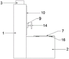
The utility model provides a manipulator equipment of polishing as shown in fig. 1-5, including cabinet 1 and the workstation 2 of setting in cabinet 1 bottom of polishing, cabinet 1's top of polishing is provided with controller 3, cabinet 1's front surface of polishing is provided with longitudinal movement subassembly 4, be provided with polishing subassembly 5 on the longitudinal movement subassembly 4, polishing subassembly 5's end connection has lateral shifting subassembly 6, lateral shifting subassembly 6 sets up on the internal surface at cabinet 1 top of polishing, 3 signal control longitudinal movement subassemblies 4 of controller, lateral shifting subassembly 6 and polishing subassembly 5, workstation 2's surface sliding ground is provided with loading board 7.
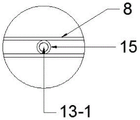
In this embodiment, the longitudinal movement assembly 4 includes the limiting frame 8, the electric slider 9 and the first slide rail 10 of setting on the cabinet 1 front surface of polishing of setting in the bottom of the limiting frame 8, the electric slider 9 slides the joint on the first slide rail 10 and with 3 signal connection of controller, the electric slider 9 can slide on the first slide rail 10, and can drive the limiting frame 8 along with the removal of electric slider 9 and move in vertical direction, thereby make the subassembly 5 of polishing advance in vertical plane.
In this embodiment, the lateral shifting subassembly 6 includes cylinder 11 and the electronic slider 9 of rigid coupling at cylinder 11 top, the bottom rigid coupling of cylinder 11 is the subassembly 5 of polishing, be provided with spout 12 on the internal surface at 1 top of cabinet of polishing, be provided with first slide rail 10 in the spout 12, the electronic slider 9 at cylinder 11 top slip joint on first slide rail 10 and with 3 signal connection of controller, the electronic slider 9 at cylinder 11 top can drive cylinder 11 and the subassembly 5 of polishing and transversely march, and cylinder 11 itself is under the drive of its piston rod 11-1, make the subassembly 5 of polishing can remove in vertical direction.
In the embodiment, the grinding assembly 5 comprises a grinding motor 13 and a grinding wheel 14 connected to an output shaft 13-1 of the grinding motor 13, the output shaft 13-1 of the grinding motor 13 penetrates through the limiting frame 8, the bottom of the air cylinder 11 is fixedly connected to a shell of the grinding motor 13, the controller 3 is in signal connection with the grinding motor 13, the grinding motor 13 is controlled through the switch matching controller 3 arranged outside, the switch can enable the mechanical switch to be a liquid crystal touch screen switch, the bearing 15 is arranged on the inner wall of the limiting frame 8, the output shaft 13-1 of the grinding motor 13 is connected with the bearing 15 in a penetrating mode, the output shaft 13-1 of the grinding motor 13 is connected in the bearing 15 in a penetrating mode, the stability of the grinding wheel 14 connected with the end portion of the grinding motor 13 is improved, and the condition that the grinding position of the grinding wheel 14 is inaccurate due to grinding vibration in the grinding process is avoided.
In this embodiment, the surface of the workbench 2 is provided with a second slide rail 16, the bearing plate 7 is clamped on the second slide rail 16 through a pulley, when the polishing work is performed, a workpiece is placed on the bearing plate 7, and the workpiece reaches a specified position by manually pushing the bearing plate 7 to operate.
When polishing, at first place the work piece of treating polishing on loading board 7, then say that loading board 7 pushes the position department of subassembly 5 of polishing, lateral shifting subassembly 6 and longitudinal movement subassembly 4 mutually support, make the subassembly 5 of polishing treat the work piece of polishing in the vertical plane and polish, specifically, the work piece is in on loading board 7, according to the height parameter that external switch set up, control the electronic slider 9 in the longitudinal movement subassembly 4 through controller 3, electronic slider 9 and the cylinder 11 in the lateral shifting subassembly 6 and the polishing motor 13 in the subassembly 5 of polishing work, polish the surface of work piece relevant position, the structure of lateral shifting subassembly 6 and longitudinal movement subassembly 4 is simpler and can realize the position shifting of subassembly 5 of polishing, it is comparatively convenient to operate and use.
Finally, it should be noted that: although the present invention has been described in detail with reference to the foregoing embodiments, it will be apparent to those skilled in the art that modifications and variations can be made in the embodiments or in part of the technical features of the embodiments without departing from the spirit and the scope of the invention.
Claims (7)
1. The utility model provides a manipulator equipment of polishing which characterized in that: including cabinet (1) and the setting of polishing workstation (2) of cabinet (1) bottom, the top of cabinet (1) of polishing is provided with controller (3), the front surface of cabinet (1) of polishing is provided with longitudinal movement subassembly (4), be provided with on the longitudinal movement subassembly (4) and polish subassembly (5), the end connection of polishing subassembly (5) has lateral shifting subassembly (6), lateral shifting subassembly (6) set up polish on the internal surface at cabinet (1) top, controller (3) signal control longitudinal movement subassembly (4), lateral shifting subassembly (6) with polish subassembly (5), the surface of workstation (2) is provided with loading board (7) with sliding.
2. The robot sharpening device of claim 1, wherein: the longitudinal moving assembly (4) comprises a limiting frame (8), an electric slider (9) arranged at the bottom of the limiting frame (8) and a first sliding rail (10) arranged on the front surface of the polishing cabinet (1), and the electric slider (9) is connected to the first sliding rail (10) in a sliding and clamping mode and is in signal connection with the controller (3).
3. The robot sharpening device of claim 2, wherein: the transverse moving assembly (6) comprises an air cylinder (11) and an electric sliding block (9) fixedly connected to the top of the air cylinder (11), and the bottom of the air cylinder (11) is fixedly connected with the grinding assembly (5).
4. The robot hand grinding apparatus according to claim 3, characterized in that: the polishing machine is characterized in that a sliding groove (12) is formed in the inner surface of the top of the polishing cabinet (1), a first sliding rail (10) is arranged in the sliding groove (12), and the electric sliding block (9) at the top of the air cylinder (11) is connected to the first sliding rail (10) in a sliding and clamping mode and is in signal connection with the controller (3).
5. The robot hand grinding apparatus according to claim 4, wherein: the grinding assembly (5) comprises a grinding motor (13) and a grinding wheel (14) connected to an output shaft (13-1) of the grinding motor (13), the output shaft (13-1) of the grinding motor (13) penetrates through the limiting frame (8), the bottom of the air cylinder (11) is fixedly connected to a shell of the grinding motor (13), and the controller (3) is in signal connection with the grinding motor (13).
6. The robot hand grinding apparatus according to claim 5, characterized in that: the inner wall of the limiting frame (8) is provided with a bearing (15), and an output shaft (13-1) of the grinding motor (13) is in through connection with the bearing (15).
7. The robot sharpening device of claim 1, wherein: the surface of the workbench (2) is provided with a second sliding rail (16), and the bearing plate (7) is clamped on the second sliding rail (16) through a pulley.
Priority Applications (1)
| Application Number | Priority Date | Filing Date | Title |
|---|---|---|---|
| CN202021803889.4U CN214519427U (en) | 2020-08-26 | 2020-08-26 | Manipulator equipment of polishing |
Applications Claiming Priority (1)
| Application Number | Priority Date | Filing Date | Title |
|---|---|---|---|
| CN202021803889.4U CN214519427U (en) | 2020-08-26 | 2020-08-26 | Manipulator equipment of polishing |
Publications (1)
| Publication Number | Publication Date |
|---|---|
| CN214519427U true CN214519427U (en) | 2021-10-29 |
Family
ID=78229023
Family Applications (1)
| Application Number | Title | Priority Date | Filing Date |
|---|---|---|---|
| CN202021803889.4U Active CN214519427U (en) | 2020-08-26 | 2020-08-26 | Manipulator equipment of polishing |
Country Status (1)
| Country | Link |
|---|---|
| CN (1) | CN214519427U (en) |
-
2020
- 2020-08-26 CN CN202021803889.4U patent/CN214519427U/en active Active
Similar Documents
| Publication | Publication Date | Title |
|---|---|---|
| CN105538111A (en) | Automatic grinding and polishing device and processing method thereof | |
| CN210909279U (en) | Numerical control rotating table surface grinding machine | |
| CN205271668U (en) | Automatic burnishing and polishing device | |
| CN214519427U (en) | Manipulator equipment of polishing | |
| CN210818931U (en) | Artificial stone bathtub surface polishing system | |
| CN211277760U (en) | High efficiency edging processing equipment | |
| CN111659952B (en) | Casting polishing control system based on man-machine cooperation and control method thereof | |
| CN210024433U (en) | Automatic numerical control lathe polishes | |
| CN210255535U (en) | Precision grinding device is used in auto-parts processing | |
| CN210731366U (en) | Laser processing device of dielectric filter with workpiece surface cleaning function | |
| CN110142666B (en) | Vibration disc feeding device of numerically controlled grinder and using method of vibration disc feeding device | |
| CN211305729U (en) | Numerical control cutter grinding machine with cutter clamping stability is good | |
| CN209394510U (en) | A kind of directional-rotation automatic sander | |
| CN218461723U (en) | Die machined part corner grinding device | |
| CN110977721A (en) | Full-automatic grinding mechanism | |
| CN216542376U (en) | A grinding device for hardware fitting | |
| CN213106243U (en) | Hardware polishing device | |
| CN109290807A (en) | Double-station precise machining device | |
| CN214162443U (en) | Computer machine case processing equipment | |
| CN217071738U (en) | Super-large numerical control machine tool base plane fine grinding equipment | |
| CN203765397U (en) | Automatic reciprocating polishing machine | |
| CN220260407U (en) | Silicon wafer polishing device | |
| CN211867258U (en) | Horizontal milling and boring machine for producing spare parts of metallurgical machinery | |
| CN213225584U (en) | Pipe joint flatness processing equipment | |
| CN219380293U (en) | A polisher for panel beating surface polishing is polished |
Legal Events
| Date | Code | Title | Description |
|---|---|---|---|
| GR01 | Patent grant | ||
| GR01 | Patent grant |