CN213770472U - Sucking disc handling device of adjustable interval - Google Patents
Sucking disc handling device of adjustable interval Download PDFInfo
- Publication number
- CN213770472U CN213770472U CN202022862423.8U CN202022862423U CN213770472U CN 213770472 U CN213770472 U CN 213770472U CN 202022862423 U CN202022862423 U CN 202022862423U CN 213770472 U CN213770472 U CN 213770472U
- Authority
- CN
- China
- Prior art keywords
- sliding
- plate
- shaped
- shaft
- fixedly arranged
- Prior art date
- Legal status (The legal status is an assumption and is not a legal conclusion. Google has not performed a legal analysis and makes no representation as to the accuracy of the status listed.)
- Active
Links
Images


Abstract
The utility model belongs to the technical field of the processing production technique and specifically relates to an interval-adjustable's sucking disc handling device, comprising a base plate, the fixed a plurality of mounting panels that are equipped with in bottom plate one side, the fixed plate that is equipped with in bottom plate one side, the fixed deflector that is equipped with in fixed plate one side, the fixed backup pad that is equipped with in bottom plate one side, deflector one side fixed connection is on backup pad one side, bottom plate one side is equipped with U type carriage, U type carriage one side is equipped with automatic accurate slider, but the deflector slidable formula is connected inboard at U type carriage, deflector one side sliding connection is equipped with the sliding plate, U type carriage fixed connection is on sliding plate one side. The utility model discloses, through setting up bottom plate, backup pad, U type carriage, multiaxis lift cylinder, U type crane, slide bar, driving shaft, driven shaft, driving gear, driven gear, transmission, make it have functions such as automatic handling, accurate transport, automatically regulated, general.
Description
Technical Field
The utility model relates to a processing production technical field especially relates to an adjustable interval's sucking disc handling device.
Background
Industrial automation is a trend of widely adopting automatic control and automatic adjustment devices in industrial production to replace manual operation machines and machine systems for processing production, and many products such as current mobile phone shells are processed by automatic production lines, and the products need to be carried and moved during processing, and many carrying movements need to be carried out by using chuck type clamps.
In the prior art, a sucker type clamp has no adjusting function, cannot adjust the distance between suckers according to the size difference of workpieces, and has no general function, so that one clamp can only be suitable for one workpiece and is not suitable for small-batch production of multiple specifications.
Disclosure of Invention
The utility model aims at solving and having among the prior art sucking disc class anchor clamps and not having regulatory function, can't adjust the distance between the sucking disc according to the variation in size of work piece, no general function to make an anchor clamps can only be applicable to a work piece, be not suitable for the shortcoming of the production of many specifications of small batch, but an adjustable interval's sucking disc handling device who provides.
In order to achieve the above purpose, the utility model adopts the following technical scheme:
the designed interval-adjustable sucker carrying device comprises a bottom plate, wherein a plurality of mounting plates are fixedly arranged on one side of the bottom plate, a fixed plate is fixedly arranged on one side of the bottom plate, a guide plate is fixedly arranged on one side of the fixed plate, a supporting plate is fixedly arranged on one side of the bottom plate, one side of the guide plate is fixedly connected on one side of the supporting plate, a U-shaped sliding frame is arranged on one side of the bottom plate, an automatic precise sliding device is arranged on one side of the U-shaped sliding frame, the guide plate is slidably connected to the inner side of the U-shaped sliding frame, a sliding plate is slidably connected on one side of the guide plate, the U-shaped sliding frame is fixedly connected on one side of the sliding plate, a multi-shaft lifting cylinder is fixedly arranged on one side of the sliding plate, the multi-shaft lifting cylinder is required to be externally connected with an electromagnetic valve through an air pipe, a connecting plate is arranged on one side of the sliding plate, and the shaft ends of the multi-shaft lifting cylinder are fixedly connected on one side of the connecting plate, one side of the connecting plate is fixedly provided with a U-shaped lifting frame, one side of the U-shaped lifting frame is provided with two sliding rods in a sliding connection way, an automatic sliding adjusting device is arranged on one side of each sliding rod, a driving shaft is arranged on the two sides of each sliding rod far away from the sliding rod, a transmission device is arranged between the driving shaft and the sliding rod, a driven shaft is arranged on one side of the driving shaft, one side of the U-shaped lifting frame is provided with a plurality of through holes, the driving shaft and the driven shaft can be rotatably connected to the inner sides of the through holes, the outer sides of the driving shafts are all fixedly provided with driving gears, the outer sides of the driven shafts are all fixedly provided with driven gears, the driven gears are in meshing transmission connection with the driving gear, the outer sides of the driving shaft and the driven shaft are fixedly provided with rotating rods, dwang one side all is equipped with the through hole, the through hole inboard all is fixed and is equipped with vacuum chuck, vacuum chuck all needs to pass through the external vacuum generator of trachea.
Preferably, automatic accurate slider is including driving the piece, driving piece one side fixed connection is on U type carriage one side, the fixed servo motor that is equipped with in backup pad one side, servo motor need pass through the external drive controller of wire and power, backup pad one side is equipped with the connecting hole, the connecting hole inboard is equipped with the A threaded rod, A threaded rod one end and servo motor's axle head fixed connection, fixed plate one side is equipped with the mounting hole, A threaded rod rotatable coupling is inboard at the mounting hole, it is equipped with the screw hole to drive piece one side, the A threaded rod passes through the screw thread driven type and connects in the screw hole inboard.
Preferably, slide bar one side all is fixed and is equipped with T type gib block, U type crane one side is fixed and is equipped with two guide holders, guide holder one side all is equipped with T type groove, the equal sliding connection of T type gib block is inboard in T type groove.
Preferably, the automatic sliding adjusting device comprises a B threaded rod, a thread groove is formed in one side of the sliding rod, the B threaded rod is connected to the inner side of the thread groove in a thread transmission mode, an adjusting motor is fixedly arranged at one end of the B threaded rod, the adjusting motor needs to be connected with a power supply and a switch through a lead, an L-shaped hole frame is fixedly arranged on one side of the U-shaped lifting frame, and the adjusting motor is fixedly connected to one side of the L-shaped hole frame.
Preferably, the transmission device comprises a rack, one side of the rack is fixedly connected to one side of the sliding rod, a transmission gear is fixedly arranged on the outer side of the driving shaft, and the transmission gear is in transmission connection with the rack through meshing.
Preferably, two dust-proof plates are fixedly arranged on one side of the bottom plate.
The utility model provides a pair of adjustable interval's sucking disc handling device, beneficial effect lies in: by arranging the bottom plate, the mounting plate, the fixing plate, the guide plate, the support plate, the U-shaped sliding frame, the sliding plate, the multi-shaft lifting cylinder, the connecting plate, the U-shaped lifting frame, the automatic precise sliding device and the vacuum suckers, when a workpiece needs to be conveyed, the two vacuum suckers can be positioned above the workpiece through the U-shaped sliding frame and the automatic precise sliding device, then the multi-shaft lifting cylinder is controlled to retract, so that the vacuum suckers can be in contact with the workpiece and tightly suck the workpiece, then the multi-shaft lifting cylinder is controlled to extend out, then the workpiece can be automatically conveyed through the U-shaped sliding frame and the automatic precise sliding device, the automatic conveying device has an automatic conveying function and higher conveying precision, a plurality of workpieces can be simultaneously sucked through arranging the plurality of rotating rods and the vacuum suckers, so that the conveying efficiency is higher, and the distance between the vacuum suckers can be adjusted by rotating and adjusting the rotating rods, the automatic rotating rod adjusting mechanism has the advantages that the automatic rotating rod adjusting mechanism has an adjusting function, the distance between the vacuum suckers can be adjusted according to the size of a workpiece, the automatic rotating rod adjusting mechanism has a general function, and the automatic rotating rod adjusting mechanism can automatically rotate and adjust the rotating rod when the adjusting motor rotates by arranging the automatic sliding adjusting device, the sliding rod, the driving shaft, the driven shaft, the driving gear, the driven gear and the transmission device, so that the automatic rotating rod adjusting mechanism has an automatic adjusting function, has higher automation degree, is convenient to use, and has the functions of automatic carrying, accurate carrying, automatic adjusting, general use and the like.
Drawings
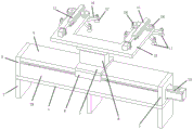
Fig. 1 is a schematic front axial view of a suction cup carrying device with adjustable spacing according to the present invention;
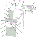
fig. 2 is a schematic view of a back axial measurement structure of the suction cup conveying device with adjustable spacing according to the present invention;
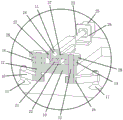
fig. 3 is a schematic front cut-away axial measurement structure diagram of the suction cup carrying device with adjustable spacing according to the present invention;
fig. 4 is a schematic side cut-away axial measurement structure diagram of the suction cup conveying device with adjustable spacing according to the present invention;
fig. 5 is a schematic front partial cutaway axial view structural diagram of the suction cup carrying device with adjustable spacing according to the present invention;
fig. 6 is a schematic side view of a partial cutaway axial view structure of the suction cup transporting device with adjustable spacing according to the present invention;
fig. 7 is the utility model provides a but interval regulation's sucking disc handling device's side part cuts open the axle and surveys the schematic diagram.
In the figure: the device comprises a base plate 1, a mounting plate 2, a fixing plate 3, a guide plate 4, a support plate 5, a sliding frame 6U-shaped, a sliding plate 7, a multi-shaft lifting cylinder 8, a connecting plate 9, a lifting frame 10U-shaped, a sliding rod 11, a driving shaft 12, a driven shaft 13, a driving gear 14, a driven gear 15, a rotating rod 16, a vacuum suction cup 17, a driving block 18, a servo motor 19, a threaded rod 20A, a guide strip 21T, a guide seat 22, a threaded rod 23B, a threaded groove 24, an adjusting motor 25, a perforated frame 26L-shaped, a rack 27, a transmission gear 28 and a dustproof plate 29.
Detailed Description
The technical solutions in the embodiments of the present invention will be described clearly and completely with reference to the accompanying drawings in the embodiments of the present invention, and it is obvious that the described embodiments are only some embodiments of the present invention, not all embodiments.
Referring to fig. 1-7, an interval-adjustable sucker transporting device comprises a bottom plate 1, a plurality of mounting plates 2 are fixedly arranged on one side of the bottom plate 1, a fixing plate 3 is fixedly arranged on one side of the bottom plate 1, a guide plate 4 is fixedly arranged on one side of the fixing plate 3, a support plate 5 is fixedly arranged on one side of the bottom plate 1, one side of the guide plate 4 is fixedly connected to one side of the support plate 5, a U-shaped sliding frame 6 is arranged on one side of the bottom plate 1, an automatic precision sliding device is arranged on one side of the U-shaped sliding frame 6, the guide plate 4 is slidably connected to the inner side of the U-shaped sliding frame 6, a sliding plate 7 is slidably connected to one side of the guide plate 4, the U-shaped sliding frame 6 is fixedly connected to one side of the sliding plate 7, a multi-shaft lifting cylinder 8 is fixedly arranged on one side of the sliding plate 7, the multi-shaft lifting cylinder 8 is externally connected with an electromagnetic valve through an air pipe, a connecting plate 9 is arranged on one side of the sliding plate 7, shaft ends of the multi-shaft lifting cylinder 8 are fixedly connected to one side of the connecting plate 9, a U-shaped lifting frame 10 is fixedly arranged on one side of a connecting plate 9, two sliding rods 11 are slidably connected and arranged on one side of the U-shaped lifting frame 10, an automatic sliding adjusting device is arranged on one side of each sliding rod 11, a driving shaft 12 is arranged on each of two sides, far away from the sliding rods 11, of each sliding rod, a transmission device is arranged between each driving shaft 12 and each sliding rod 11, a driven shaft 13 is arranged on each side of each driving shaft 12, a plurality of through holes are formed in one side of the U-shaped lifting frame 10, the driving shafts 12 and the driven shafts 13 can be rotatably connected to the inner sides of the through holes, a driving gear 14 is fixedly arranged on the outer side of each driving shaft 12, driven gears 15 are fixedly arranged on the outer sides of the driven shafts 13, the driven gears 15 are connected with the driving gears 14 in a meshing transmission mode, the driving shafts 12, the outside of driven shaft 13 all fixedly is equipped with dwang 16, and dwang 16 one side all is equipped with the through hole, and the through hole inboard all fixedly is equipped with vacuum chuck 17, and vacuum chuck 17 all needs to pass through the external vacuum generator of trachea.
Concretely, automatic accurate slider is including driving piece 18, 18 one side fixed connection of driving piece is on 6 one side of U type carriage, 5 one side fixed servo motor 19 that is equipped with of backup pad, servo motor 19 need be through the external drive control ware of wire and power, 5 one side of backup pad is equipped with the connecting hole, the connecting hole inboard is equipped with A threaded rod 20, the axle head fixed connection of 20 one end of A threaded rod and servo motor 19, 3 one side of fixed plate is equipped with the mounting hole, A threaded rod 20 rotatable coupling is inboard at the mounting hole, it is equipped with the screw hole to drive 18 one side of piece, A threaded rod 20 passes through the screw thread driven type and connects at the screw hole inboard.
Specifically, 11 one sides of slide bar are all fixed and are equipped with T type gib block 21, and U type crane 10 one side is fixed and is equipped with two guide holders 22, and guide holder 22 one side all is equipped with T type groove, and the equal sliding connection of T type gib block 21 is inboard in T type groove.
Specifically, the automatic sliding adjusting device includes B threaded rod 23, and 11 one side of slide bar is equipped with thread groove 24, and B threaded rod 23 passes through thread drive formula to be connected at thread groove 24 inboardly, and the fixed accommodate motor 25 that is equipped with of B threaded rod 23 one end, accommodate motor 25 need be through wire external power supply and switch, and U type crane 10 one side is fixed to be equipped with L type area hole frame 26, and accommodate motor 25 fixed connection is on L type area hole frame 26 one side.
Specifically, the transmission device comprises a rack 27, one side of the rack 27 is fixedly connected to one side of the sliding rod 11, a transmission gear 28 is fixedly arranged on the outer side of the driving shaft 12, and the transmission gear 28 is in meshing transmission connection with the rack 27.
Specifically, two dust-proof plates 29 are fixedly arranged on one side of the bottom plate 1.
The utility model is provided with a bottom plate 1, a mounting plate 2, a fixing plate 3, a guide plate 4, a support plate 5, a U-shaped sliding frame 6, a sliding plate 7, a multi-shaft lifting cylinder 8, a connecting plate 9, a U-shaped lifting frame 10, an automatic precise sliding device and a vacuum sucker 17, when a workpiece needs to be transported, the two vacuum suckers 17 can be positioned above the workpiece through the U-shaped sliding frame 6 and the automatic precise sliding device, then the multi-shaft lifting cylinder 8 is controlled to retract, the vacuum sucker 17 is contacted with the workpiece, the workpiece is tightly sucked at the same time, then the multi-shaft lifting cylinder 8 is controlled to extend out, then the workpiece can be automatically transported through the U-shaped sliding frame 6 and the automatic precise sliding device, the workpiece has an automatic transporting function and higher transporting precision, and the workpiece can be simultaneously sucked through the arrangement of a plurality of rotating rods 16 and the vacuum suckers 17, thereby having higher transporting efficiency, and rotate and adjust the dwang 16, can adjust the distance between the vacuum chuck 17, make it have regulatory function, can adjust the distance between the vacuum chuck 17 according to the work piece size, make it have general function, through setting up the automatic sliding adjusting device, the slide bar 11, the driving shaft 12, the driven shaft 13, the driving gear 14, the driven gear 15, transmission, when adjusting the motor 25 and rotating, can make the dwang 16 rotate automatically and adjust, make it have the automatic regulating function, have higher degree of automation, convenient to use, have functions such as automatic handling, accurate transport, automatically regulated, general.
The above, only be the concrete implementation of the preferred embodiment of the present invention, but the protection scope of the present invention is not limited thereto, and any person skilled in the art is in the technical scope of the present invention, according to the technical solution of the present invention and the utility model, the concept of which is equivalent to replace or change, should be covered within the protection scope of the present invention.
Claims (6)
1. The sucking disc carrying device with the adjustable interval comprises a bottom plate (1) and is characterized in that a plurality of mounting plates (2) are fixedly arranged on one side of the bottom plate (1), a fixing plate (3) is fixedly arranged on one side of the bottom plate (1), a guide plate (4) is fixedly arranged on one side of the fixing plate (3), a supporting plate (5) is fixedly arranged on one side of the bottom plate (1), one side of the guide plate (4) is fixedly connected onto one side of the supporting plate (5), a U-shaped sliding frame (6) is arranged on one side of the bottom plate (1), an automatic accurate sliding device is arranged on one side of the U-shaped sliding frame (6), the guide plate (4) is connected to the inner side of the U-shaped sliding frame (6) in a sliding mode, a sliding plate (7) is arranged on one side of the guide plate (4) in a sliding mode, a multi-shaft lifting cylinder (8) is fixedly arranged on one side of the sliding plate (7), the multi-shaft lifting air cylinder (8) is externally connected with an electromagnetic valve through an air pipe, a connecting plate (9) is arranged on one side of the sliding plate (7), shaft ends of the multi-shaft lifting air cylinder (8) are fixedly connected to one side of the connecting plate (9), a U-shaped lifting frame (10) is fixedly arranged on one side of the connecting plate (9), two sliding rods (11) are slidably connected to one side of the U-shaped lifting frame (10), an automatic sliding adjusting device is arranged on one side of each sliding rod (11), a driving shaft (12) is arranged on two sides, far away from the sliding rods (11), a transmission device is arranged between the driving shaft (12) and the sliding rods (11), a driven shaft (13) is arranged on one side of the driving shaft (12), a plurality of through holes are formed in one side of the U-shaped lifting frame (10), and the driving shaft (12), all fixed driving gear (14) that is equipped with in driving shaft (12) outside, driven shaft (13) outside is all fixed and is equipped with driven gear (15), driven gear (15) all are connected through the meshing transmission with driving gear (14), all fixed dwang (16) that is equipped with in driving shaft (12), driven shaft (13) outside, dwang (16) one side all is equipped with the through hole, all fixed vacuum chuck (17) that are equipped with in through hole inboard, vacuum chuck (17) all need be through the external vacuum generator of trachea.
2. An adjustable pitch suction cup handling device according to claim 1, the automatic accurate sliding device comprises a driving block (18), one side of the driving block (18) is fixedly connected with one side of the U-shaped sliding frame (6), a servo motor (19) is fixedly arranged on one side of the supporting plate (5), the servo motor (19) is required to be externally connected with a driving controller and a power supply through a lead, one side of the supporting plate (5) is provided with a connecting hole, the inner side of the connecting hole is provided with an A threaded rod (20), one end of the A threaded rod (20) is fixedly connected with the shaft end of the servo motor (19), one side of the fixed plate (3) is provided with a mounting hole, the A threaded rod (20) is rotatably connected to the inner side of the mounting hole, and a threaded hole is formed in one side of the driving block (18), and the A threaded rod (20) is connected to the inner side of the threaded hole in a threaded transmission mode.
3. The interval-adjustable sucker conveying device as claimed in claim 1, wherein the sliding rod (11) is fixedly provided with a T-shaped guide strip (21) on one side, the U-shaped lifting frame (10) is fixedly provided with two guide seats (22) on one side, the guide seats (22) are provided with a T-shaped groove on one side, and the T-shaped guide strips (21) are slidably connected to the inner side of the T-shaped groove.
4. The interval-adjustable sucker conveying device according to claim 1, wherein the automatic sliding adjusting device comprises a B threaded rod (23), a threaded groove (24) is formed in one side of the sliding rod (11), the B threaded rod (23) is connected to the inner side of the threaded groove (24) in a threaded transmission mode, an adjusting motor (25) is fixedly arranged at one end of the B threaded rod (23), the adjusting motor (25) needs to be externally connected with a power supply and a switch through a lead, an L-shaped hole frame (26) is fixedly arranged on one side of the U-shaped lifting frame (10), and the adjusting motor (25) is fixedly connected to one side of the L-shaped hole frame (26).
5. The interval-adjustable sucker conveying device as claimed in claim 1, wherein the transmission device comprises a rack (27), one side of the rack (27) is fixedly connected to one side of the sliding rod (11), a transmission gear (28) is fixedly arranged on the outer side of the driving shaft (12), and the transmission gear (28) is in meshing transmission connection with the rack (27).
6. The adjustable-pitch sucker conveying device as claimed in claim 1, wherein two dust-proof plates (29) are fixedly arranged on one side of the base plate (1).
Priority Applications (1)
| Application Number | Priority Date | Filing Date | Title |
|---|---|---|---|
| CN202022862423.8U CN213770472U (en) | 2020-12-03 | 2020-12-03 | Sucking disc handling device of adjustable interval |
Applications Claiming Priority (1)
| Application Number | Priority Date | Filing Date | Title |
|---|---|---|---|
| CN202022862423.8U CN213770472U (en) | 2020-12-03 | 2020-12-03 | Sucking disc handling device of adjustable interval |
Publications (1)
| Publication Number | Publication Date |
|---|---|
| CN213770472U true CN213770472U (en) | 2021-07-23 |
Family
ID=76895729
Family Applications (1)
| Application Number | Title | Priority Date | Filing Date |
|---|---|---|---|
| CN202022862423.8U Active CN213770472U (en) | 2020-12-03 | 2020-12-03 | Sucking disc handling device of adjustable interval |
Country Status (1)
| Country | Link |
|---|---|
| CN (1) | CN213770472U (en) |
Cited By (1)
| Publication number | Priority date | Publication date | Assignee | Title |
|---|---|---|---|---|
| CN113441611A (en) * | 2021-07-26 | 2021-09-28 | 深圳鑫宏力精密工业有限公司 | Numerical control programming and automatic processing control device for mobile phone mold forming part |
-
2020
- 2020-12-03 CN CN202022862423.8U patent/CN213770472U/en active Active
Cited By (1)
| Publication number | Priority date | Publication date | Assignee | Title |
|---|---|---|---|---|
| CN113441611A (en) * | 2021-07-26 | 2021-09-28 | 深圳鑫宏力精密工业有限公司 | Numerical control programming and automatic processing control device for mobile phone mold forming part |
Similar Documents
| Publication | Publication Date | Title |
|---|---|---|
| WO2022262076A1 (en) | Conveying type loading and unloading robot and loading and unloading method | |
| CN213770472U (en) | Sucking disc handling device of adjustable interval | |
| CN111204613A (en) | Unloading mechanism in transmission for full-automatic wire winding production line | |
| CN111993133A (en) | Intelligent robot for machining automobile parts and use method thereof | |
| CN210339517U (en) | Plate processing production line for centralized blanking | |
| CN209240757U (en) | A kind of plate automation machining production line | |
| CN215357430U (en) | Feeding and discharging device of waterwheel type machine tool | |
| CN106985221B (en) | Numerical control table top mechanism with multi-section feeding, powerful elliptic sucker and servo clamping hand | |
| CN112264865A (en) | Full-automatic plate-shaped workpiece automatic grinding line | |
| CN210436886U (en) | Multi-head numerical control engraving and milling machine capable of achieving circular processing | |
| CN110587359A (en) | Automatic detect material feeding unit of automatic troubleshooting | |
| CN217097806U (en) | Automatic feeding manipulator | |
| CN217141911U (en) | Automatic workpiece polishing and punching device | |
| CN217143237U (en) | Automatic go up unloading processing lathe | |
| CN210501609U (en) | Embrace box transfer mechanism | |
| CN214212606U (en) | Multi-shaft double-channel intelligent engraving and milling machine | |
| CN211337554U (en) | Rapid lifting and conveying device for machining | |
| CN210818642U (en) | Automatic detect material feeding unit of automatic troubleshooting | |
| CN211440338U (en) | Blanking device of five-surface processing center | |
| CN210818639U (en) | Automatic feeding and discharging device for CNC engraving and milling machine | |
| CN209337615U (en) | A kind of production line convenient for the plate unified allocation of materials to lower units | |
| CN112719609A (en) | Multi-shaft double-channel intelligent engraving and milling machine | |
| CN215746707U (en) | Feeding device and pipe cutting machine | |
| CN215150628U (en) | Small component trimmer | |
| CN109079656A (en) | A kind of support device for thin-walled parts polishing |
Legal Events
| Date | Code | Title | Description |
|---|---|---|---|
| GR01 | Patent grant | ||
| GR01 | Patent grant |