CN212333780U - A conveyer for different granularity abrasive materials - Google Patents
A conveyer for different granularity abrasive materials Download PDFInfo
- Publication number
- CN212333780U CN212333780U CN202020625973.5U CN202020625973U CN212333780U CN 212333780 U CN212333780 U CN 212333780U CN 202020625973 U CN202020625973 U CN 202020625973U CN 212333780 U CN212333780 U CN 212333780U
- Authority
- CN
- China
- Prior art keywords
- car
- motor
- lifting
- transport
- lifting frame
- Prior art date
- Legal status (The legal status is an assumption and is not a legal conclusion. Google has not performed a legal analysis and makes no representation as to the accuracy of the status listed.)
- Active
Links
Images


Abstract
The utility model discloses a conveyer for abrasive materials with different granularities, which comprises a vertical frame, a transverse frame arranged above the vertical frame, a charging car and material bins arranged at the two sides of the vertical frame, wherein the vertical frame is provided with a chain and a transmission mechanism, a lifting rod is fixed on the chain, the transverse frame comprises a transverse track and a transport car walking on the transverse track, the lower part of the transport car is glidingly arranged on the transverse track through two groups of track wheels, the bottom of the transport car is provided with an opening and closing bottom plate, the lifting rod is provided with a lifting frame and a turnover mechanism, the lifting mechanism is started to drive the charging car to lift, when the charging car rises to the vicinity of the transport car, the turnover mechanism is started, the abrasive materials are poured into the transport car, the transport car moves along the track under the driving of the track wheels and stops on the corresponding material bins, a cylinder is started, the opening and, the grinding materials are poured into the corresponding storage bins, the whole process does not need to consume manpower, and the production efficiency is improved.
Description
Technical Field
The utility model relates to the field of mechanical equipment, more specifically say that it relates to a conveyer that is used for different granularity abrasive materials.
Background
Abrasives are used in a very wide range of industrial applications, in particular in the machining of high-precision or low-roughness parts or particularly hard parts, and are indispensable for grinding. The granularity of the abrasive refers to the grain size of the abrasive, in the production and manufacturing process of the abrasive product, the processed abrasive product needs to be subjected to granularity screening, and the screened abrasives with different granularities are respectively stored in different bins.
In the existing abrasive production line, the abrasives need to be manually transported and poured after being screened, and because the weight of the abrasives is large, the granularity classification is multiple, the manual transportation process is time-consuming and labor-consuming, and the efficiency is low, an automatic abrasive transporting device is designed to make up the defects of manual transportation.
SUMMERY OF THE UTILITY MODEL
Not enough to prior art exists, the utility model aims to provide a conveyer for different granularity abrasive materials, it is through setting up the skip, the transport vechicle, elevating system and tilting mechanism, and the abrasive material that will put into the skip transports near the transport vechicle above the feed bin through elevating system to turn over the abrasive material through tilting mechanism and deliver to the transport vechicle, under the conveying of rail wheel, the abrasive material in the transport vechicle is delivered to the feed bin, and whole process realizes automaticly, avoids manual operation's numerous and diverse.
In order to achieve the above purpose, the utility model provides a following technical scheme:
a conveying device for abrasive materials with different particle sizes comprises a vertical rack, a transverse rack arranged above the vertical rack, a charging car for bearing the abrasive materials with different particle sizes, and a storage bin arranged on two sides of the vertical rack and located below the transverse rack, wherein a chain moving up and down and a transmission mechanism for driving the chain to move are arranged in the height direction of the center of the vertical rack;
the horizontal rack comprises two horizontal rails arranged in parallel and a transport vehicle which reciprocates on the horizontal rails, the lower part of the transport vehicle is arranged on the horizontal rails in a sliding way through two groups of rail wheels, one group of rail wheels are driving wheels, the bottom of the transport vehicle is provided with an opening and closing bottom plate, and the opening and closing bottom plate of the transport vehicle is driven by a cylinder; the lifting rod is provided with a lifting frame used for clamping the charging car, and a turnover mechanism used for turning over the charging car and pouring the grinding materials into the transport car, and the initial position of the transport car is positioned right above the lifting frame.
According to the technical scheme, the lifting mechanism is started, the lifting mechanism drives the chain to further drive the loading car on the lifting frame to lift in the vertical direction, the pulley and the slide rail are matched to provide a certain acting force for lifting of the lifting frame, the lifting frame can lift smoothly, and the lifting frame can lift without deviating from the direction.
The utility model discloses further set up to: the transmission mechanism comprises a first gear set and a first motor for driving the gear set to rotate, the first motor is fixed to the upper end of the vertical rack, the gear set comprises a driving gear and a driven gear, the driving gear is coaxially fixed with an output shaft of the first motor, the driven gear is rotatably supported at the lower end of the vertical rack, and the chain is lapped on the driving gear and the driven gear.
Starting the first motor, the gear set drives the chain to rotate on the gear set, and then the lifting frame is driven to lift in the vertical direction.
The utility model discloses further set up to: tilting mechanism includes dwang and drive dwang along its axle center pivoted motor two, motor two is fixed on the lifter, the one end of dwang and motor two's output shaft coaxial fixation, and the rocking arm and the crane fixed connection of dwang.
When the charging car filled with the grinding materials ascends to the position near the transport car, the second motor is started, and the rotating rod drives the lifting frame to rotate, so that automatic material pouring is realized.
The utility model discloses further set up to: the inner side wall of the lifting frame is provided with a guide groove, and the outer side wall of the charging car is provided with a clamping part corresponding to the guide groove.
The clamping part and the guide groove are clamped together, so that the charging car filled with the grinding materials can be fixed on the lifting frame, and the charging car can be conveniently detached from the lifting frame at any time.
The utility model discloses further set up to: the crane is provided with an extension hopper, and the side edge of the extension hopper is abutted to the opening of the transport vehicle.
When the charging car rises to the position near the transport car along with the lifting frame, the second motor is started, and the grinding materials in the charging car are poured into the transport car along the hopper, so that the grinding materials are more conveniently transported.
The utility model discloses further set up to: wheels are fixedly connected to the lower portion of the charging car.
The wheels are arranged to facilitate the charging car to convey the screened abrasive to the lifting frame.
To sum up, the utility model discloses following beneficial effect has:
(1) the second motor is fixed on the lifting rod through the arrangement of the turnover mechanism, one end of the rotating rod is connected with the second motor, the rotating arm of the rotating rod is fixedly connected with the lifting frame, the second motor is started, and the rotating rod drives the lifting frame to rotate, so that automatic material pouring can be realized;
(2) the guide groove is formed in the inner side wall of the lifting frame, the clamping portion corresponding to the guide groove is arranged on the outer side wall of the charging car, and the clamping portion and the guide groove are clamped together to fix the charging car filled with the grinding materials on the lifting frame and facilitate the charging car to be detached from the lifting frame at any time;
(3) through the below fixed connection wheel at the charging car, the setting up of wheel makes things convenient for the transport vechicle to transport the abrasive material that sieves to the crane.
Drawings
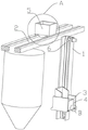
Fig. 1 is a first overall schematic diagram of the present invention;
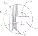
fig. 2 is a second overall schematic diagram of the present invention;
FIG. 3 is a schematic structural view of the lifting frame and the lifting mechanism;
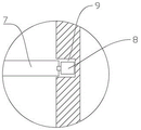
FIG. 4 is an enlarged view taken at A in FIG. 2;
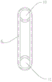
FIG. 5 is a schematic structural view of a pulley and a slide rail;
FIG. 6 is a schematic view of the gear set and chain configuration;
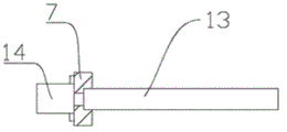
FIG. 7 is a schematic structural view of the turnover mechanism and the lifting rod;
fig. 8 is an enlarged view at B in fig. 2.
Reference numerals: 1. a vertical frame; 2. a transverse frame; 3. a lifting frame; 4. charging a car; 5. a transport vehicle; 6. a chain; 7. a lifting rod; 8. a pulley; 9. a guide rail; 10. a driving gear; 11. a driven gear; 12. a first motor; 13. rotating the rod; 14. a second motor; 15. a guide groove; 16. a clamping part; 17. an extension hopper; 18. a wheel; 19. transverse rails 20 and an opening and closing bottom plate.
Detailed Description
The present invention will be described in detail with reference to the accompanying drawings.
Example (b): a transport device for abrasives of different particle sizes is used for transporting abrasives of different particle sizes over a silo for holding abrasives. As shown in fig. 1 and 2, the grinding device comprises a vertical frame 1, a transverse frame 2 arranged above the vertical frame 1, a charging car 4 for loading grinding materials with different particle sizes, and bins arranged at two sides of the vertical frame 1 and below the transverse frame 2. Referring to fig. 3, a chain 6 moving up and down and a transmission mechanism for driving the chain 6 to move are arranged in the height direction of the center of the vertical frame 1, and a lifting rod 7 is fixed on the chain 6. Referring to fig. 4, the transverse frame 2 includes two parallel transverse rails 19 and a transport vehicle 5 that travels on the transverse rails 19 in a reciprocating manner, the lower portion of the transport vehicle 5 is slidably mounted on the transverse rails 19 through two sets of rail wheels, one set of rail wheels is a driving wheel, an opening and closing bottom plate 20 is disposed at the bottom of the transport vehicle 5, the opening and closing bottom plate 20 of the transport vehicle 5 is driven by a cylinder to open and close, the specific structure can be realized through the prior art, and those skilled in the art can understand the structure and implement the structure, which will not be described in detail herein. The lifting rod 7 is provided with a lifting frame 3 for clamping the charging car 4 and a turnover mechanism for turning over the charging car 4 and pouring the grinding materials into the transport car 5, and the initial position of the transport car 5 is positioned right above the lifting frame 3. The lifting mechanism is started, the lifting mechanism drives the chain 6 to further drive the charging car 4 on the lifting frame 3 to lift in the vertical direction, when the charging car 4 rises to the position near the transport car 5, the turnover mechanism is started, the grinding materials in the charging car 4 are poured into the transport car 5, the transport car 5 moves along the rail under the driving of the rail wheels and stops on the corresponding storage bin, the air cylinder is started, the opening and closing bottom plate 20 is opened, the transport car 5 pours the grinding materials into the corresponding storage bin, the whole process does not need to consume manpower, the complexity of manual operation is eliminated, and the production efficiency is improved.
Referring to fig. 5, in order to make the lifting frame 3 rise and fall smoothly and ensure that the lifting frame 3 does not deviate from the lifting direction, pulleys 8 are arranged at two ends of the lifting rod 7, a guide rail 9 matched with the pulleys 8 is arranged on the vertical rack 1, the pulleys 8 are slidably arranged in the guide rail 9, and the lifting rod 7 is connected with the turnover mechanism.
Referring to fig. 6, the transmission mechanism includes a gear set and a first motor 12 for driving the gear set to rotate, the gear set is set to a driving gear 10 and a driven gear 11, the driving gear 10 rotates and is supported at the upper end of the rack, the driven gear 11 rotates and is supported at the lower end of the vertical rack 1, the chain 6 is lapped on the driving gear 10 and the driven gear 11, a first motor 12 is started, the driving gear 10 drives the driven gear 11 to rotate and then drives the chain 6 to rotate on the gear, and the gear further drives the lifting frame 3 to lift in the vertical direction.
Referring to fig. 3 and 7, the turnover mechanism includes a rotating rod 13 and a second motor 14 for driving the rotating rod 13 to rotate along the axis thereof, the second motor 14 is fixed on the lifting rod 7, one end of the rotating rod 13 is coaxially fixed with an output shaft of the second motor 14, and the rotating arm of the rotating rod 13 is fixedly connected with the lifting frame 3. When the charging car 4 ascends to the vicinity of the transport car 5 along with the crane 3, the second motor 14 is started, the rotating rod 13 rotates by taking the axis of the rotating rod 13 as an axis, and the grinding materials in the charging car 4 are poured into the transport car 5.
Referring to fig. 8, a guide groove 15 is arranged on the inner side wall of the lifting frame 3, a clamping part 16 corresponding to the guide groove 15 is arranged on the outer side wall of the charging car 4, and the clamping part 16 and the guide groove 15 are clamped together to fix the charging car 4 filled with the grinding materials on the lifting frame 3. The lifting frame 3 is provided with the extension hopper 17, the side edge of the extension hopper 17 is abutted to the opening of the transport cart 5, when the charge car 4 rises to the position near the transport cart 5 along with the lifting frame 3, the second motor 14 is started, and the grinding materials in the charge car 4 are poured into the transport cart 5 along the hopper, so that the grinding materials are more conveniently transported. In order to facilitate the conveying of the screened abrasive material to the lifting frame 3 by the charging car 4, wheels 18 are fixedly connected below the charging car 4.
During operation, the first motor 12 is started, the driving gear 10 drives the driven gear 11 to rotate so as to drive the chain 6 to rotate on the gear, the gear further drives the lifting frame 3 to lift in the vertical direction, when the loading car 4 rises to the position near the transport car 5 along with the lifting frame 3, the second motor 14 is started, abrasive materials in the loading car 4 are poured into the transport car 5, the transport car 5 moves along the rail under the driving of the rail wheels and stops on the corresponding storage bin, the air cylinder is started, the opening and closing bottom plate is opened, and the transport car 5 pours the abrasive materials into the corresponding storage bin.
It is above only the utility model discloses a preferred embodiment, the utility model discloses a scope of protection does not only confine above-mentioned embodiment, the all belongs to the utility model discloses a technical scheme under the thinking all belongs to the utility model discloses a scope of protection. It should be noted that, for those skilled in the art, various modifications and decorations can be made without departing from the principle of the present invention, and these modifications and decorations should also be regarded as the protection scope of the present invention.
Claims (6)
1. The conveying device for the abrasives with different granularities is characterized by comprising a vertical rack (1), a transverse rack (2) arranged above the vertical rack (1), a charging car (4) used for bearing the abrasives with different granularities, and a storage bin which is arranged at two sides of the vertical rack (1) and is positioned below the transverse rack (2), wherein a chain (6) moving up and down and a transmission mechanism for driving the chain (6) to move are arranged in the height direction of the center of the vertical rack (1), a lifting rod (7) is fixed on the chain (6), pulleys (8) are arranged at two ends of the lifting rod (7), guide rails (9) matched with the pulleys (8) are arranged on the inner walls of two sides of the vertical rack (1), and the pulleys (8) are slidably installed in the guide rails (9);
the horizontal rack (2) comprises two horizontal rails (19) arranged in parallel and a transport vehicle (5) which travels on the horizontal rails (19) in a reciprocating manner, the lower part of the transport vehicle (5) is slidably mounted on the horizontal rails (19) through two groups of rail wheels, one group of rail wheels are driving wheels, an opening and closing bottom plate (20) is arranged at the bottom of the transport vehicle (5), and the opening and closing bottom plate (20) of the transport vehicle is driven by a cylinder;
the lifting rod (7) is provided with a lifting frame (3) used for clamping the charging car (4) and a turnover mechanism used for turning over the charging car (4) and pouring the grinding materials into the transport car (5), and the initial position of the transport car (5) is positioned right above the lifting frame (3).
2. The conveying device for the grinding materials with different particle sizes as claimed in claim 1, wherein the transmission mechanism comprises a gear set and a first motor (12) for driving the gear set to rotate, the first motor (12) is fixed at the upper end of the vertical rack (1), the gear set comprises a driving gear (10) and a driven gear (11), the driving gear (10) is coaxially fixed with an output shaft of the first motor (12), the driven gear (11) is rotatably supported at the lower end of the vertical rack (1), and the chain (6) is lapped on the driving gear (10) and the driven gear (11).
3. The conveying device for the grinding materials with different particle sizes as claimed in claim 1, wherein the turnover mechanism comprises a rotating rod (13) and a second motor (14) which drives the rotating rod (13) to rotate along the axis of the rotating rod, the second motor (14) is fixed on the lifting rod (7), one end of the rotating rod (13) is coaxially fixed with an output shaft of the second motor (14), and the rotating arm of the rotating rod (13) is fixedly connected with the lifting frame (3).
4. The conveying device for the grinding materials with different particle sizes as claimed in claim 1, wherein a guide groove (15) is arranged on the inner side wall of the lifting frame (3), and a clamping part (16) corresponding to the guide groove (15) is arranged on the outer side wall of the charging car (4).
5. The conveying device for the grinding materials with different particle sizes as claimed in claim 1 is characterized in that an extension hopper (17) is arranged on the lifting frame (3), and the side edge of the extension hopper (17) is abutted with the opening of the conveying vehicle (5).
6. The device for transporting abrasive materials of different granulometry according to claim 1, characterized in that wheels (18) are fixedly connected under said charging carriage (4).
Priority Applications (1)
| Application Number | Priority Date | Filing Date | Title |
|---|---|---|---|
| CN202020625973.5U CN212333780U (en) | 2020-04-23 | 2020-04-23 | A conveyer for different granularity abrasive materials |
Applications Claiming Priority (1)
| Application Number | Priority Date | Filing Date | Title |
|---|---|---|---|
| CN202020625973.5U CN212333780U (en) | 2020-04-23 | 2020-04-23 | A conveyer for different granularity abrasive materials |
Publications (1)
| Publication Number | Publication Date |
|---|---|
| CN212333780U true CN212333780U (en) | 2021-01-12 |
Family
ID=74074130
Family Applications (1)
| Application Number | Title | Priority Date | Filing Date |
|---|---|---|---|
| CN202020625973.5U Active CN212333780U (en) | 2020-04-23 | 2020-04-23 | A conveyer for different granularity abrasive materials |
Country Status (1)
| Country | Link |
|---|---|
| CN (1) | CN212333780U (en) |
-
2020
- 2020-04-23 CN CN202020625973.5U patent/CN212333780U/en active Active
Similar Documents
| Publication | Publication Date | Title |
|---|---|---|
| CN110789953B (en) | Automatic equipment for loading and unloading goods in railway transportation | |
| CN212333780U (en) | A conveyer for different granularity abrasive materials | |
| CN211870802U (en) | Automatic feeding device for crushing vehicle | |
| CN210286040U (en) | Stacking assembly of loading robot | |
| CN214732074U (en) | Automatic AGV dolly of unloading | |
| CN212355377U (en) | Belt feeder mechanical transmission | |
| CN210735136U (en) | Bidirectional loading gate | |
| CN209849046U (en) | Silicon raw material processing system | |
| CN209777744U (en) | cross fortune material slip table discharge apparatus | |
| CN109019078B (en) | Automatic loading and unloading car system device | |
| CN210212179U (en) | A get meal device for takeaway car | |
| CN206842588U (en) | A kind of material is unloaded conveying arrangement | |
| CN117088141B (en) | Powder unloading system | |
| CN111268384A (en) | Automobile part processing system | |
| CN220617578U (en) | Combined conveying device for powder and aggregate | |
| CN216805981U (en) | Tubular sealant automatic storage and transportation line | |
| CN220702653U (en) | Loading device for bulk cargo finished products of production line | |
| CN212049410U (en) | Two-degree-of-freedom sealed unloading device | |
| CN216104358U (en) | Vertical double-screw unloader | |
| CN220765636U (en) | Charging tray feeding and discharging lifting structure | |
| CN110451291B (en) | Palletizing assembly of loading robot | |
| CN211594276U (en) | Rotary movable loading and unloading conveyor | |
| CN215590765U (en) | Auxiliary transportation device for mining machinery | |
| CN210366036U (en) | Movable spiral feeding weighing system | |
| CN210392955U (en) | Sign indicating number material assembly with rotation function |
Legal Events
| Date | Code | Title | Description |
|---|---|---|---|
| GR01 | Patent grant | ||
| GR01 | Patent grant |