CN212291900U - Door type conveying mechanism with different clamping specifications for vehicle door integrated forming processing - Google Patents
Door type conveying mechanism with different clamping specifications for vehicle door integrated forming processing Download PDFInfo
- Publication number
- CN212291900U CN212291900U CN202021534639.5U CN202021534639U CN212291900U CN 212291900 U CN212291900 U CN 212291900U CN 202021534639 U CN202021534639 U CN 202021534639U CN 212291900 U CN212291900 U CN 212291900U
- Authority
- CN
- China
- Prior art keywords
- conveying mechanism
- gear
- fixedly connected
- type conveying
- door type
- Prior art date
- Legal status (The legal status is an assumption and is not a legal conclusion. Google has not performed a legal analysis and makes no representation as to the accuracy of the status listed.)
- Active
Links
Images

Landscapes
- Automobile Manufacture Line, Endless Track Vehicle, Trailer (AREA)
Abstract
The utility model discloses a door type conveying mechanism for clamping different specifications for the integrated forming processing of vehicle doors, which comprises a supporting plate, wherein one end of the supporting plate is fixedly connected with a first motor base, one side of the first motor base is fixedly provided with a first reciprocating motor, the output end of the first reciprocating motor is in transmission connection with one end of a first transmission shaft, the other end of the first transmission shaft passes through the supporting plate and is fixedly connected with one side of a rotating disc, the middle part of the rotating disc is fixedly provided with a first gear, one side of the first gear is in meshing connection with one side of a second gear, the second gear is fixedly arranged at the middle part of a first rotating cylinder, the utility model discloses a door type conveying mechanism for the integrated forming processing of vehicle doors, the structure of the whole device is simpler, the door type conveying mechanism is beneficial to the daily maintenance and the repair work of workers to the device, the height of the whole device and the position of the clamp can be adjusted to adapt to the vehicle doors with different specifications.
Description
Technical Field
The utility model relates to a centre gripping conveying mechanism, in particular to door integrated into one piece processing is with different specification gate-type conveying mechanism of centre gripping belongs to industrial technology field.
Background
Along with the degree of chinese industrialization is higher and higher, more and more people need the car, the car price is also lower and lower simultaneously, the output of car is also higher and higher, the door is the important spare part of car, the processing of door needs centre gripping conveying mechanism, but general centre gripping conveying mechanism structure is comparatively complicated, be unfavorable for the daily maintenance of staff and maintenance work, and can only the door of centre gripping same specification, be unfavorable for improving work efficiency, therefore we make the improvement to this, propose a door type conveying mechanism of different specifications of centre gripping for door integrated into one piece processing.
SUMMERY OF THE UTILITY MODEL
The utility model aims at providing a door type conveying mechanism of different specifications of centre gripping is used in door integrated into one piece processing to solve general centre gripping conveying mechanism structure that proposes in the above-mentioned background art comparatively complicated, be unfavorable for staff's daily maintenance and maintenance work, can only the door of centre gripping same kind of specification moreover, be unfavorable for improving work efficiency's problem.
In order to achieve the above object, the utility model provides a following technical scheme: a door type conveying mechanism for clamping door type conveying of different specifications for vehicle door integrated forming machining comprises a supporting plate, wherein one end of the supporting plate is fixedly connected with a first motor base, one side of the first motor base is fixedly provided with a first reciprocating motor, the output end of the first reciprocating motor is in transmission connection with one end of a first transmission shaft, the other end of the first transmission shaft penetrates through the supporting plate and is fixedly connected with one side of a rotating disc, the middle of the rotating disc is fixedly provided with a first gear, one side of the first gear is in meshing connection with one side of a second gear, the second gear is fixedly arranged in the middle of a first rotating cylinder, the bottom of the first rotating cylinder is in rotating connection with a rotating groove formed in the top of a connecting disc, the bottom of the connecting disc is fixedly connected with the top of the supporting plate, and the top of the first rotating cylinder is fixedly connected with a, the top of second transmission shaft and the bottom fixed connection of connecting box, the one end fixed mounting of connecting box has the reciprocal motor of second, the output of the reciprocal motor of second passes the connecting box and is connected with the one end transmission of screw shaft, the middle part slip of screw shaft is provided with the holder, the bottom of holder and the top fixed connection of link, the bottom of link passes the sliding tray that the connecting box bottom was seted up and the top fixed connection of anchor clamps.
As a preferred technical scheme of the utility model, the equal fixed mounting in four corners of backup pad bottom has electronic hydraulic stem, one of them connecting rod fixedly connected with conveying mechanism is passed through to one side of electronic hydraulic stem.
As the utility model discloses a preferred technical scheme, conveying mechanism comprises conveyer belt base and conveyer belt, the equal fixed mounting in both ends of conveyer belt has conveyer belt base.
As a preferred technical scheme of the utility model, the soft cushion of one side fixedly connected with of anchor clamps bottom, a plurality of archs of opposite side fixedly connected with of anchor clamps bottom.
Compared with the prior art, the beneficial effects of the utility model are that: the utility model relates to a door integrated into one piece processing is with different specification gate-type conveying mechanism of centre gripping, whole device structure is comparatively simple, is favorable to the staff to the routine maintenance and the maintenance work of device, improves the working life of whole device, can adapt to the door of different specifications with this through the position of adjusting the height of whole device and anchor clamps.
Drawings
Fig. 1 is a schematic structural view of the present invention;
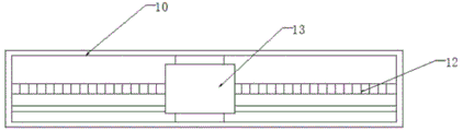
fig. 2 is a top view of the connection box of the present invention.
In the figure: 1. a support plate; 2. a first motor base; 3. a first reciprocating motor; 4. a first drive shaft; 5. rotating the disc; 6. a first gear; 7. a second gear; 8. a first rotating cylinder; 9. a second drive shaft; 10. a connecting box; 11. a second reciprocating motor; 12. a threaded shaft; 13. a holder; 14. a connecting frame; 15. a clamp; 16. a conveyor belt; 17. an electro-hydraulic lever.
Detailed Description
The technical solutions in the embodiments of the present invention will be described clearly and completely with reference to the accompanying drawings in the embodiments of the present invention, and it is obvious that the described embodiments are only some embodiments of the present invention, not all embodiments. Based on the embodiments in the present invention, all other embodiments obtained by a person skilled in the art without creative work belong to the protection scope of the present invention.
Referring to fig. 1-2, the utility model provides a door type conveying mechanism for integrally forming and processing doors with different clamping specifications, which comprises a supporting plate 1, wherein one end of the supporting plate 1 is fixedly connected with a first motor base 2, one side of the first motor base 2 is fixedly provided with a first reciprocating motor 3, the output end of the first reciprocating motor 3 is in transmission connection with one end of a first transmission shaft 4, the other end of the first transmission shaft 4 passes through the supporting plate 1 and is fixedly connected with one side of a rotary disk 5, the middle part of the rotary disk 5 is fixedly provided with a first gear 6, one side of the first gear 6 is in meshing connection with one side of a second gear 7, the second gear 7 is fixedly arranged at the middle part of a first rotary cylinder 8, the bottom of the first rotary cylinder 8 is rotatably connected with a rotary groove arranged at the top of a connecting disk, the bottom of the connecting disk is fixedly connected with the top of the supporting plate 1, the top of the first, the top of second transmission shaft 9 and the bottom fixed connection of connecting box 10, the one end fixed mounting of connecting box 10 has second reciprocating motor 11, the output of second reciprocating motor 11 passes connecting box 10 and is connected with the one end transmission of threaded shaft 12, the middle part of threaded shaft 12 slides and is provided with holder 13, the bottom of holder 13 and the top fixed connection of link 14, the sliding tray that link 14's bottom was seted up is passed to the bottom of connecting box 10 and is connected with the top fixed connection of anchor clamps 15.
Preferably, four corners of the bottom of the supporting plate 1 are fixedly provided with electric hydraulic rods 17, one side of one electric hydraulic rod 17 is fixedly connected with a conveying mechanism through a connecting rod, and the height of the whole device can be adjusted, so that the clamping of vehicle doors of different specifications is facilitated.
Preferably, conveying mechanism comprises conveyer belt base and conveyer belt 16, and the equal fixed mounting in both ends of conveyer belt 16 has the conveyer belt base, and fixture is after the door centre gripping, then steady putting on conveyer belt 16, carries the door through conveyer belt 16 at last.
Preferably, one side of the bottom of the clamp 15 is fixedly connected with a soft rubber cushion, and the other side of the bottom of the clamp 15 is fixedly connected with a plurality of protrusions, so that the painted side of the vehicle door can be prevented from being scratched, and the clamping force of the clamp 15 can be enhanced.
When the door type conveying mechanism is used, firstly, the whole device is opened through an external switch, the first reciprocating motor 3 starts to work to sequentially drive the first transmission shaft 4, the rotary disk 5, the first gear 6, the second gear 7 and the first rotary cylinder 8 to rotate and then drive the second transmission shaft 9 and the connecting box 10, when the gripper 13 grips the door through the control clamp 15, the first reciprocating motor 3 starts to rotate reversely to sequentially drive the first transmission shaft 4, the rotary disk 5, the first gear 6, the second gear 7 and the first rotary cylinder 8 to rotate and then drive the second transmission shaft 9 and the connecting box 10 to rotate reversely, the gripper 15 stably puts the gripped door on the conveyor belt 16, and finally, the door is conveyed through the conveyor belt 16, when the doors with different specifications are met, the whole device can be lifted by the electric hydraulic rod 17 at the bottom of the device, the second reciprocating motor 11 drives the threaded shaft 12 to rotate, and the position of the clamp 13 and the position of the clamp 15 are adjusted, so that different specifications of the vehicle door can be adapted.
In the description of the present invention, it should be understood that the indicated orientation or positional relationship is based on the orientation or positional relationship shown in the drawings, and is only for convenience of description and simplification of description, and does not indicate or imply that the indicated device or element must have a particular orientation, be constructed and operated in a particular orientation, and thus should not be construed as limiting the present invention.
In the present invention, unless otherwise explicitly specified or limited, for example, it may be fixedly connected, detachably connected, or integrated; can be mechanically or electrically connected; they may be directly connected or indirectly connected through an intermediate medium, and may be connected through the inside of two elements or in an interaction relationship between two elements, unless otherwise specifically defined, and the specific meaning of the above terms in the present invention will be understood by those skilled in the art according to specific situations.
Although embodiments of the present invention have been shown and described, it will be appreciated by those skilled in the art that changes, modifications, substitutions and alterations can be made in these embodiments without departing from the principles and spirit of the invention, the scope of which is defined in the appended claims and their equivalents.
Claims (4)
1. The door type conveying mechanism comprises a supporting plate (1) and is characterized in that one end of the supporting plate (1) is fixedly connected with a first motor base (2), one side of the first motor base (2) is fixedly provided with a first reciprocating motor (3), the output end of the first reciprocating motor (3) is in transmission connection with one end of a first transmission shaft (4), the other end of the first transmission shaft (4) penetrates through the supporting plate (1) and is fixedly connected with one side of a rotating disc (5), the middle of the rotating disc (5) is fixedly provided with a first gear (6), one side of the first gear (6) is in meshing connection with one side of a second gear (7), the second gear (7) is fixedly arranged in the middle of a first rotating cylinder (8), the bottom of the first rotating cylinder (8) is rotatably connected with a rotating groove formed in the top of a connecting disc, the bottom of connection pad and the top fixed connection of backup pad (1), the top fixedly connected with second transmission shaft (9) of first rotatory cylinder (8), the top of second transmission shaft (9) and the bottom fixed connection of connecting box (10), the one end fixed mounting of connecting box (10) has second reciprocating motor (11), the output of second reciprocating motor (11) passes connecting box (10) and is connected with the one end transmission of screw spindle (12), the middle part slip of screw spindle (12) is provided with holder (13), the bottom of holder (13) and the top fixed connection of link (14), the bottom of link (14) passes the sliding tray that connecting box (10) bottom was seted up and the top fixed connection of anchor clamps (15).
2. The door type conveying mechanism for clamping different specifications for the integrated forming and processing of the vehicle door as claimed in claim 1 is characterized in that: four corners of backup pad (1) bottom are all fixed mounting have electronic hydraulic stem (17), one of them one side of electronic hydraulic stem (17) is through connecting rod fixedly connected with conveying mechanism.
3. The door type conveying mechanism for clamping different specifications for the integrated forming and processing of the vehicle door as claimed in claim 2, is characterized in that: conveying mechanism comprises conveyer belt base and conveyer belt (16), the equal fixed mounting in both ends of conveyer belt (16) has the conveyer belt base.
4. The door type conveying mechanism for clamping different specifications for the integrated forming and processing of the vehicle door as claimed in claim 1 is characterized in that: one side fixedly connected with soft cushion of anchor clamps (15) bottom, the opposite side fixedly connected with of anchor clamps (15) bottom is a plurality of archs.
Priority Applications (1)
| Application Number | Priority Date | Filing Date | Title |
|---|---|---|---|
| CN202021534639.5U CN212291900U (en) | 2020-07-29 | 2020-07-29 | Door type conveying mechanism with different clamping specifications for vehicle door integrated forming processing |
Applications Claiming Priority (1)
| Application Number | Priority Date | Filing Date | Title |
|---|---|---|---|
| CN202021534639.5U CN212291900U (en) | 2020-07-29 | 2020-07-29 | Door type conveying mechanism with different clamping specifications for vehicle door integrated forming processing |
Publications (1)
| Publication Number | Publication Date |
|---|---|
| CN212291900U true CN212291900U (en) | 2021-01-05 |
Family
ID=73938568
Family Applications (1)
| Application Number | Title | Priority Date | Filing Date |
|---|---|---|---|
| CN202021534639.5U Active CN212291900U (en) | 2020-07-29 | 2020-07-29 | Door type conveying mechanism with different clamping specifications for vehicle door integrated forming processing |
Country Status (1)
| Country | Link |
|---|---|
| CN (1) | CN212291900U (en) |
Cited By (1)
| Publication number | Priority date | Publication date | Assignee | Title |
|---|---|---|---|---|
| CN112875619A (en) * | 2021-01-26 | 2021-06-01 | 祝天晗 | Strong adaptability's spacing conveying mechanism in batches for filling production |
-
2020
- 2020-07-29 CN CN202021534639.5U patent/CN212291900U/en active Active
Cited By (1)
| Publication number | Priority date | Publication date | Assignee | Title |
|---|---|---|---|---|
| CN112875619A (en) * | 2021-01-26 | 2021-06-01 | 祝天晗 | Strong adaptability's spacing conveying mechanism in batches for filling production |
Similar Documents
| Publication | Publication Date | Title |
|---|---|---|
| CN212291900U (en) | Door type conveying mechanism with different clamping specifications for vehicle door integrated forming processing | |
| CN110181265B (en) | Ball valve body and valve cover manufacturing device | |
| CN211030050U (en) | Pneumatic control workpiece grabbing robot | |
| CN213316239U (en) | Wisdom is high efficiency goods letter sorting machine people for commodity circulation | |
| CN210735526U (en) | High-efficient machine that moves that carries | |
| CN218428240U (en) | A manipulator structure for transmission shaft processing | |
| CN111891740A (en) | Door type conveying mechanism with different clamping specifications for vehicle door integrated forming processing | |
| CN218927806U (en) | Automatic control device for mechanical arm | |
| CN212608073U (en) | Stereo set transport mechanism | |
| CN213290268U (en) | Rotary positioning manipulator | |
| CN215848260U (en) | Solar panel terminal box self-adaptation manipulator | |
| CN210476980U (en) | Automobile parts processing robot | |
| CN211003476U (en) | Battery core clamping and feeding device | |
| CN210451174U (en) | Cutting device is used in aluminium alloy processing | |
| CN110281200B (en) | Automatic assembly system for film making clamp assembly | |
| CN208413249U (en) | A kind of robot manipulator structure of numerically-controlled machine tool | |
| CN216328302U (en) | Manipulator for electric automatization | |
| CN220077817U (en) | Sucking and rotating mechanism for products | |
| CN218398117U (en) | Automatic change manipulator | |
| CN219542944U (en) | Hardware processing positioning device | |
| CN204431039U (en) | Multi-station processing equipment pick and place materials device | |
| CN217451869U (en) | Double-station flexible stamping manipulator | |
| CN220375742U (en) | Mechanical automation grabbing device for assembly line | |
| CN211990749U (en) | Efficient energy-saving electric screw forging press | |
| CN216837053U (en) | Novel automatically controlled torsion spiral cover machine |
Legal Events
| Date | Code | Title | Description |
|---|---|---|---|
| GR01 | Patent grant | ||
| GR01 | Patent grant |