CN211776079U - Building body greenhouse building with photovoltaic shutter and solar chimney for double power generation - Google Patents
Building body greenhouse building with photovoltaic shutter and solar chimney for double power generation Download PDFInfo
- Publication number
- CN211776079U CN211776079U CN201922462196.7U CN201922462196U CN211776079U CN 211776079 U CN211776079 U CN 211776079U CN 201922462196 U CN201922462196 U CN 201922462196U CN 211776079 U CN211776079 U CN 211776079U
- Authority
- CN
- China
- Prior art keywords
- heat
- chimney
- building
- building body
- heat collecting
- Prior art date
- Legal status (The legal status is an assumption and is not a legal conclusion. Google has not performed a legal analysis and makes no representation as to the accuracy of the status listed.)
- Active
Links
Images


Classifications
-
- Y—GENERAL TAGGING OF NEW TECHNOLOGICAL DEVELOPMENTS; GENERAL TAGGING OF CROSS-SECTIONAL TECHNOLOGIES SPANNING OVER SEVERAL SECTIONS OF THE IPC; TECHNICAL SUBJECTS COVERED BY FORMER USPC CROSS-REFERENCE ART COLLECTIONS [XRACs] AND DIGESTS
- Y02—TECHNOLOGIES OR APPLICATIONS FOR MITIGATION OR ADAPTATION AGAINST CLIMATE CHANGE
- Y02B—CLIMATE CHANGE MITIGATION TECHNOLOGIES RELATED TO BUILDINGS, e.g. HOUSING, HOUSE APPLIANCES OR RELATED END-USER APPLICATIONS
- Y02B10/00—Integration of renewable energy sources in buildings
- Y02B10/10—Photovoltaic [PV]
-
- Y—GENERAL TAGGING OF NEW TECHNOLOGICAL DEVELOPMENTS; GENERAL TAGGING OF CROSS-SECTIONAL TECHNOLOGIES SPANNING OVER SEVERAL SECTIONS OF THE IPC; TECHNICAL SUBJECTS COVERED BY FORMER USPC CROSS-REFERENCE ART COLLECTIONS [XRACs] AND DIGESTS
- Y02—TECHNOLOGIES OR APPLICATIONS FOR MITIGATION OR ADAPTATION AGAINST CLIMATE CHANGE
- Y02B—CLIMATE CHANGE MITIGATION TECHNOLOGIES RELATED TO BUILDINGS, e.g. HOUSING, HOUSE APPLIANCES OR RELATED END-USER APPLICATIONS
- Y02B10/00—Integration of renewable energy sources in buildings
- Y02B10/30—Wind power
-
- Y—GENERAL TAGGING OF NEW TECHNOLOGICAL DEVELOPMENTS; GENERAL TAGGING OF CROSS-SECTIONAL TECHNOLOGIES SPANNING OVER SEVERAL SECTIONS OF THE IPC; TECHNICAL SUBJECTS COVERED BY FORMER USPC CROSS-REFERENCE ART COLLECTIONS [XRACs] AND DIGESTS
- Y02—TECHNOLOGIES OR APPLICATIONS FOR MITIGATION OR ADAPTATION AGAINST CLIMATE CHANGE
- Y02E—REDUCTION OF GREENHOUSE GAS [GHG] EMISSIONS, RELATED TO ENERGY GENERATION, TRANSMISSION OR DISTRIBUTION
- Y02E10/00—Energy generation through renewable energy sources
- Y02E10/40—Solar thermal energy, e.g. solar towers
- Y02E10/47—Mountings or tracking
-
- Y—GENERAL TAGGING OF NEW TECHNOLOGICAL DEVELOPMENTS; GENERAL TAGGING OF CROSS-SECTIONAL TECHNOLOGIES SPANNING OVER SEVERAL SECTIONS OF THE IPC; TECHNICAL SUBJECTS COVERED BY FORMER USPC CROSS-REFERENCE ART COLLECTIONS [XRACs] AND DIGESTS
- Y02—TECHNOLOGIES OR APPLICATIONS FOR MITIGATION OR ADAPTATION AGAINST CLIMATE CHANGE
- Y02E—REDUCTION OF GREENHOUSE GAS [GHG] EMISSIONS, RELATED TO ENERGY GENERATION, TRANSMISSION OR DISTRIBUTION
- Y02E10/00—Energy generation through renewable energy sources
- Y02E10/50—Photovoltaic [PV] energy
-
- Y—GENERAL TAGGING OF NEW TECHNOLOGICAL DEVELOPMENTS; GENERAL TAGGING OF CROSS-SECTIONAL TECHNOLOGIES SPANNING OVER SEVERAL SECTIONS OF THE IPC; TECHNICAL SUBJECTS COVERED BY FORMER USPC CROSS-REFERENCE ART COLLECTIONS [XRACs] AND DIGESTS
- Y02—TECHNOLOGIES OR APPLICATIONS FOR MITIGATION OR ADAPTATION AGAINST CLIMATE CHANGE
- Y02E—REDUCTION OF GREENHOUSE GAS [GHG] EMISSIONS, RELATED TO ENERGY GENERATION, TRANSMISSION OR DISTRIBUTION
- Y02E10/00—Energy generation through renewable energy sources
- Y02E10/70—Wind energy
- Y02E10/72—Wind turbines with rotation axis in wind direction
-
- Y—GENERAL TAGGING OF NEW TECHNOLOGICAL DEVELOPMENTS; GENERAL TAGGING OF CROSS-SECTIONAL TECHNOLOGIES SPANNING OVER SEVERAL SECTIONS OF THE IPC; TECHNICAL SUBJECTS COVERED BY FORMER USPC CROSS-REFERENCE ART COLLECTIONS [XRACs] AND DIGESTS
- Y02—TECHNOLOGIES OR APPLICATIONS FOR MITIGATION OR ADAPTATION AGAINST CLIMATE CHANGE
- Y02E—REDUCTION OF GREENHOUSE GAS [GHG] EMISSIONS, RELATED TO ENERGY GENERATION, TRANSMISSION OR DISTRIBUTION
- Y02E10/00—Energy generation through renewable energy sources
- Y02E10/70—Wind energy
- Y02E10/728—Onshore wind turbines
Abstract
The utility model provides a building body greenhouse building of two electricity generations of photovoltaic tripe and solar energy chimney which characterized in that: the sunward side of the building body 1 is provided with a side heat collecting shed 2, the top of the building body is provided with a top heat collecting shed 3, the top of the top heat collecting shed 3 is connected with a chimney 4, a turbine generator 5 is arranged in the chimney 4, the bottom of the side heat collecting shed 2 is provided with an air inlet 6, heat dissipation and heat insulation integrated photovoltaic panel shutters 7 are arranged in the side heat collecting shed 2 and the top heat collecting shed 3, and the sunward side of the room of the building body 1 is a multi-layer transparent plate full-lighting floor wall window 8. The building body greenhouse building with the photovoltaic panel and the solar chimney double power generation, which is nearly perfect in various aspects such as ventilation, heat preservation, sun shading, full utilization of solar energy and the like, is provided by combining the large windowing and heat preservation technology of a sunlight greenhouse, the heat dissipation and heat insulation integrated photovoltaic panel louver and building body solar chimney power generation technology, the phase change energy storage technology which is easy to replace and the total heat exchange ventilation and loss reduction technology.
Description
Technical Field
The utility model relates to a solar greenhouse building.
Background
1. With the development of social productivity, energy shortage, greenhouse effect and environmental pollution have become global problems. The search for new clean energy utilization technology has become one of the hot technologies of the world research. Solar energy is almost inexhaustible as a clean renewable energy source for human beings. Among various renewable energy sources, solar energy is the most important basic energy source, and biomass energy, wind energy, water energy and tidal energy are all derived from solar energy. At present, the solar energy utilization technology is mature, and the solar energy utilization technology forms an industry which belongs to solar water heaters and solar energy power generation, and the photovoltaic power generation and solar chimney power generation in the solar energy power generation technology have wide prospects. A common solar chimney power station (also called a solar hot air flow power station) is composed of 3 basic parts, namely a solar heat collection shed, a solar chimney and a turbine generator set. The solar heat collection shed is arranged on the ground with strong solar radiation and better heat insulation performance, a certain gap is formed between the heat collection shed and the ground, and ambient air can enter the system: a chimney is arranged in the middle of the heat collecting shed at a certain distance from the ground, a turbine is arranged at the bottom of the chimney, sunlight irradiates the heat collecting shed, the ground below the heat collecting shed absorbs solar radiation energy penetrating through the covering layer and heats air between the ground and the covering layer of the heat collecting shed, so that the temperature of air in the heat collecting shed is increased, the density of the air is reduced, the air is caused to rise along the chimney, and meanwhile, cold air around the heat collecting shed continuously enters a system for supplement, and therefore air circulation flow is formed. When the air in the heat collecting shed flows to the bottom of the chimney, strong air flow is formed in the chimney due to the chimney effect, and the strong air flow is used for pushing a turbine arranged at the bottom of the chimney to drive a generator to generate electricity. In the air flow process, the air is heated first, and the solar energy is converted into the internal energy of the air, along with three energy conversion processes: the internal energy is converted into kinetic energy due to the rising flow of air in the chimney; when air flows to the turbine, the air flow pushes the turbine rotor to rotate, and the kinetic energy is converted into the required electric energy. The solar chimney power generation technology has the following characteristics: compared with other power generation technologies, the device is simple, the operation cost is low, the solar energy source is wide, the device is more suitable for areas with few population, the environment effect is good, the environment is not polluted, and the ventilation environment of the building is improved and adjusted. Compared with the common solar hot air power station, the building surface and top solar hot air power station has the following advantages: the method has the advantages that new land occupation is not required to be approved, the light and thin metal frame paving glass is fixed on the existing building, the cost is low, a tall chimney which occupies main cost, is high in maintenance cost and has collapse danger is not required to be built, the building and maintenance cost is lower, the operation is safer, the building can be paved regardless of the size, and the maintenance is simple.
2. The existing human-living building has huge energy consumption, the proportion of the building energy consumption in the total human energy consumption is nearly 40 percent, the reason is that the heat preservation is insufficient, the wall body heat preservation is not enough, the most serious is a window, a thin layer of glass and a thin layer of glass can not play much heat preservation effect at all, the boiler is continuously burnt, the radiator continuously heats a room, the thin window exhales hot air outwards in a calling way (like a person wears a large cotton wadded jacket but is open in cold winter)! Secondly, modern buildings almost have no sun-shading measures, sunlight passes through a balcony window to heat a room in summer, and the room can be cooled only by an air conditioner. Statistically, the energy dissipated by a building through a window accounts for about 30% of the energy consumed by the building. The heat preservation tripe of certain thickness in the current product solves the heat preservation and the sunshade two problems of window body simultaneously, but the facade of the heat preservation tripe of certain thickness (more than 30 millimeters) has blockked some sunshine and has got into indoor when window body daylighting in winter, not only influences the sight but also has increased the heating expense.
3. Even in cold winter, the temperature in the greenhouse is higher than 30 ℃ at minus ten degrees outdoors in sunny days, sometimes, a part of heat needs to be artificially discharged due to overhigh temperature, the temperature is rapidly reduced to 5-10 ℃ at night due to the absence of heat storage facilities, the heat in the daytime is wasted in vain, and the temperature at night is less than 10 ℃. Although the temperature can be raised by heating with fuel at night, the running cost is very high due to the large consumption of the fuel. The surplus heat in the daytime and the deficiency of heat at night are outstanding contradictions in greenhouse environment control, and one idea for solving the contradictions is to store the surplus heat in the daytime and release the surplus heat to a greenhouse for heating at night.
4. Generally, the photoelectric conversion efficiency of a photovoltaic cell is 10% -20%, and in the operation process, most of solar radiation energy which is not utilized except for part of reflected energy is absorbed by the cell and converted into heat energy; if the absorbed heat cannot be removed in time, the temperature of the battery is gradually increased, the power generation efficiency is reduced (according to statistics, the generated power is attenuated by 0.4% when the temperature of the battery assembly rises by 1 ℃), and the photovoltaic battery can be rapidly aged and the service life of the photovoltaic battery is shortened when the photovoltaic battery works at a high temperature for a long time. Present battery cooling technique is mainly the improvement of backplate material and structure, and current backplate material is generally formed by several kinds of macromolecular material complex, if adopt TPT, TPE, FPE isotructure, nevertheless because macromolecular material's coefficient of heat conductivity is generally all lower unable effective heat dissipation for the heat that the subassembly operation produced can not effectual derivation, leads to the heat accumulation. The photovoltaic cell heat dissipation method includes passive heat dissipation and active heat dissipation. The former takes away the battery heat by the natural flow of the atmosphere, and the latter drives a fan or a pump by electric power to force air, water or other fluids to flow through a heat dissipation device artificially arranged on the solar battery assembly to strengthen the heat dissipation process of the battery, or only adds the heat dissipation device on the solar battery assembly to strengthen the natural convection heat dissipation. Because the concentrated solar cell module works under several to tens of suns, the temperature of the cell can reach thousands of degrees when the heat dissipation is not enhanced, and the module is damaged, so the concentrated solar cell module adopts the enhanced heat dissipation measure, for example, the chinese patent CN101145743 solar cell high-efficiency power generation heat dissipation system adds a heat conduction sheet and a heat dissipation component at the lower part of the solar cell module to enhance the heat dissipation to the atmosphere, the chinese patent CN201000896 water-cooled photovoltaic power generation system bonds a heat conduction water pipe below the solar cell module by heat conduction silica gel, and the water in the pipe circulates and flows to cool the concentrated solar cell. In addition, in the solar photovoltaic thermal comprehensive utilization, for example, chinese patent CN1716642, hybrid photoelectric photo-thermal collector, chinese patent CN1563844 solar cogeneration device, and chinese patent CN1988183 solar cell electric heating combination device all utilize water to circulate through the back of the solar cell module to extract heat energy, and simultaneously play a role in reducing the temperature of the solar cell. For a common flat-plate solar cell module, it is generally considered that setting a complex heat dissipation system is not significant, basically, no special consideration is given to the heat dissipation problem, and the working temperature of the flat-plate solar cell module is usually over 50 ℃. The best heat dissipation effect at present is a heat dissipation technology of a micro heat pipe (thermal conductivity is 5000 times that of aluminum and 200 times that of graphene) flat plate attached backboard-CN 200810239002.0 photovoltaic cell heat dissipation device: one side of the micro heat pipe radiating flat plate is attached to the back of the photovoltaic cell panel, the radiating flat plate is of a hollow structure, a large number of micro-hole pipe groups or micro-groove groups are arranged in the radiating flat plate in the same direction, working media such as methanol are filled in the micro-hole pipe groups or the micro-groove groups, the micro-hole pipe groups or the micro-groove groups naturally form the micro heat pipe structure, one side of the radiating flat plate, which is attached to the photovoltaic cell panel, is a heat absorbing surface, and part or all of the rest side. The heat dissipation effect is very good, but the price is 1-2 times of that of the photovoltaic panel. For these components, it is the direction to reduce their working temperature by simple and effective heat dissipation measures, for example, by using all-metal back sheets (ZL 200820200742.9, CN 201120084141.8), but the requirement of back sheet material for long-term insulation cannot be met well by relying on surface oxide layers alone, so that the components face the safety problem in the practical process, and the too thick metal layer adopted is not favorable for component transportation and cost reduction.
In the search of Chinese and foreign patents, designs of solar hot air flow power stations on the surfaces and tops of buildings are some, like energy-saving buildings and the like with cooling structures in Chinese patent 2011103396740, the design in the ventilation aspect is good, but the heat preservation and sun shading of the buildings and the full utilization of solar energy are not in place. And the 2013205658475 solar chimney power station greenhouse building (improving the heat insulation and power generation efficiency and improving the power generation efficiency).
Disclosure of Invention
The utility model discloses be promptly to sunlight greenhouse's big window daylighting thermal-arrest and heat preservation technique, heat dissipation thermal-insulated integrative photovoltaic board tripe and building body solar energy chimney power generation technique, easily change phase transition energy storage technique and full heat exchange ventilation and loss reduction technique merge together, provide one kind in ventilation, heat preservation, sunshade of building to and solar energy make full use of etc. many-sided photovoltaic board that all is close to perfect and the building body greenhouse building of two electricity generations of solar energy chimney. The technical scheme of the utility model is that: the utility model provides a building body greenhouse building of two electricity generations of photovoltaic board and solar chimney, includes building body 1, side thermal-arrest canopy 2, top thermal-arrest canopy 3, chimney 4, turbogenerator 5, air intake 6, the thermal-insulated integrative photovoltaic board tripe 7 of heat dissipation, the full daylighting of multilayer transparent plate falls to ground wall window 8, characterized in that: the sunward side of the building body 1 is provided with a side heat collecting shed 2, the top of the building body is provided with a top heat collecting shed 3, the top of the top heat collecting shed 3 is connected with a chimney 4, a turbine generator 5 is arranged in the chimney 4, the bottom of the side heat collecting shed 2 is provided with an air inlet 6, heat dissipation and heat insulation integrated photovoltaic panel shutters 7 are arranged in the side heat collecting shed 2 and the top heat collecting shed 3, and the sunward side of the room of the building body 1 is a multi-layer transparent plate full-lighting floor wall window 8. When sunshine is used in winter, the heat dissipation and heat insulation integrated photovoltaic panel shutter (hereinafter referred to as shutter) is erected to be approximately parallel to the sunshine, part of the sunshine is injected into a room from a shutter gap to form a part of sunshine power generation and heat heating of the room, the floor, the wall and the furniture in the room store heat (better, the paved phase change energy storage floor 9 stores more heat), at the moment, the heat dissipation structure of the shutter quickly heats the air flowing through the shutter to cool the shutter, the density of the air is lowered due to heating, buoyancy is generated to flow upwards to generate ascending airflow, the ascending airflow of the sunny side of the whole building is converged to a chimney on the top of the building and pushes a turbine generator to generate power, and after the sunshine is cooled down, the shutter is laid flat to become a heat insulation board; in summer sunshine, the louver is adjusted to a position which is approximately at a right angle with the sunshine to generate electricity, meanwhile, the louver shields the sunshine and prevents the sunshine from being emitted into a room, so that the room can be as cool as a tree shadow, and years of practice prove that: in the areas north of Yangtze river in China, as long as the heat insulation of the house is qualified, sunlight cannot be directly irradiated into a room from the south window, an air conditioner can be basically omitted, at the moment, the heat dissipation structure of the louver rapidly heats the air flowing through the heat dissipation structure to cool the louver, the density of the air is reduced due to heating, buoyancy is generated to flow upwards, and the ascending air flow of the whole building facing to the sun surface is collected to a chimney on the top of the building and pushes a turbine generator to generate electricity.
The utility model has the advantages that: the solar chimney power generation technology and the photovoltaic power generation technology which are simplest and lowest in cost are grafted to the conventional building, meanwhile, the large windowing and heat preservation technology of the sunlight greenhouse changes the conventional building into the greenhouse building capable of storing solar energy, the shortcoming of the conventional building on insufficient sunlight utilization is overcome, and the building can be opened in cold days to collect the cheapest and greenest energy to the maximum extent-solar energy! (note: the conventional building only has windows on the south wall for lighting, the sunlight injection amount in cold days is very limited, but the greenhouse building can fully light on the south wall and the west wall, the sunlight can fully warm the indoor, and after the sunlight is cooled down, the heat dissipation and insulation integrated photovoltaic plate shutter full heat preservation window body can be closed), so that the heating is basically omitted; and the heat dissipation and insulation integrated photovoltaic panel shutter can shield sunlight from being injected into a room while generating power in summer, so that an air conditioner is omitted. Air conditioning and heating are main energy consumption of commercial buildings, the two items are omitted, and when sunlight is sufficient, electricity generated by photovoltaic and chimney can completely meet daily electricity consumption of residents (televisions, computers, lighting, kitchen and bathroom electrical appliances).
Drawings
The invention will be further described with reference to the following figures and examples:
fig. 1 is a schematic structural diagram of the present invention.
Fig. 2 is a schematic structural diagram of the present invention.
Fig. 3 is a schematic structural diagram of the present invention.
Fig. 4 is a schematic structural diagram of the present invention.
Fig. 5 is a schematic structural diagram of the present invention.
Fig. 6 is a schematic structural diagram of the present invention.
Fig. 7 is a schematic structural diagram of the present invention.
Fig. 8 is a schematic structural diagram of the present invention.
Fig. 9 is a schematic structural diagram of the present invention.
Fig. 10 is a schematic structural diagram of the present invention.
Fig. 11 is a schematic structural diagram of the present invention.
In the figure, 1, a building body, 2, a side heat collection shed, 3, a top heat collection shed, 4, a chimney, 5, a turbine generator, 6, an air inlet door, 7, a heat dissipation and heat insulation integrated photovoltaic panel louver, 8, a multilayer transparent panel full-daylighting floor wall window, 9, a phase change energy storage floor, 10, a bagged phase change material, 11, an ultrathin sound-insulation and light-transmission partition wall, a heat insulation board composite fin metal back board, b, a conventional fin, c, a hook pin fin, d, a row hole channel, e, a surface board, f, a photovoltaic cell, g, a heat insulation board, g1. hollow microsphere matrix laminate, g2, aerogel, h, a barb hook pin, i, an electric heating wire, an x, a surface yarn layer, a y. surface yarn layer, z. spacing yarn, z', spacing yarn resin connecting ribs, A, a micro-heat tube board, B, a heat insulation layer, C, a photovoltaic cell, a D, micro-groove group, E, F, a heat dissipation device, a G, micro-heat working medium end pressing, I. the back plate, J.
Detailed Description
In fig. 1, a building structure without a heat dissipation and insulation integrated photovoltaic panel louver 7 is shown, a side heat-collecting shed 2 is arranged on four sides (at least south and west sunny sides) of the building 1, a top heat-collecting shed 3 is arranged on the top of the building, the top of the top heat-collecting shed 3 is connected with a chimney 4, a turbine generator 5 is arranged in the chimney 4, and an air inlet 6 is arranged on the lower portion of the side heat-collecting shed 2.
In fig. 2, a building structure with a heat dissipation and insulation integrated photovoltaic panel louver 7 is shown, four surfaces (at least south and west two sunny surfaces) of a building 1 are provided with side heat-collecting sheds 2, the top of each side heat-collecting shed is provided with a top heat-collecting shed 3, the top of each top heat-collecting shed 3 is connected with a chimney 4, a turbine generator 5 is arranged in each chimney 4, the lower part of each side heat-collecting shed 2 is provided with an air inlet 6, and the middle part of the too high building side heat-collecting shed is additionally provided with the air inlet to introduce cool air for cooling and insulation of the heat dissipation integrated photovoltaic. The side heat collecting sheds 2 and the top heat collecting sheds 3 are internally provided with heat dissipation and insulation integrated photovoltaic panel shutters 7, and the sunny side of the room of the building body 1 is a multi-layer transparent plate full-lighting floor-falling wall window 8 (which is shielded by the shutters, and can be seen in fig. 3). When sunshine is used in winter, the heat dissipation and heat insulation integrated photovoltaic panel shutter (hereinafter referred to as shutter) is erected to be approximately parallel to the sunshine, part of the sunshine is injected into a room from a shutter gap to form a part of sunshine power generation and heat heating of the room, the floor, the wall and the furniture in the room store heat (better, the paved phase change energy storage floor 9 stores more heat), at the moment, the heat dissipation structure of the shutter quickly heats the air flowing through the shutter to cool the shutter, the density of the air is lowered due to heating, buoyancy is generated to flow upwards to generate ascending airflow, the ascending airflow of the sunny side of the whole building is converged to a chimney on the top of the building and pushes a turbine generator to generate power, and after the sunshine is cooled down, the shutter is laid flat to become a heat insulation board; in summer sunshine, the louver is adjusted to a position which is approximately at a right angle with the sunshine to generate electricity, meanwhile, the louver shields the sunshine and prevents the sunshine from being emitted into a room, so that the room can be as cool as a tree shadow, and years of practice prove that: in the areas north of Yangtze river in China, as long as the heat insulation of the house is qualified, sunlight cannot be directly irradiated into a room from the south window, an air conditioner can be basically omitted, at the moment, the heat dissipation structure of the louver rapidly heats the air flowing through the heat dissipation structure to cool the louver, the density of the air is reduced due to heating, buoyancy is generated to flow upwards, and the ascending air flow of the whole building facing to the sun surface is collected to a chimney on the top of the building and pushes a turbine generator to generate electricity.
In fig. 3, a part of a room is cut out to show the application state of the louver in summer and winter sunshine, the upper drawing shows that in winter sunshine, the louver 7 (louver for short later) of the heat dissipation and heat insulation integrated photovoltaic panel is erected to be approximately parallel to the sunshine, part of the sunshine is made to penetrate into the room through the multi-layer transparent plate full-lighting floor-falling wall window 8 from the gap of the louver to form part of sunshine power generation and part of the sunshine to heat the room, the wall, furniture and the phase change energy storage floor 9 in the room store heat, and after the sunshine is cooled down, the louver is laid flat to become a whole-face heat insulation board heat preservation room; in the lower graph, when sunlight is in summer, the louver is adjusted to be at a position close to a right angle with the sunlight to generate electricity, and meanwhile, the louver shields the sunlight from being emitted into a room, so that the room is cool like a tree under shade. If the outdoor temperature is too high, the louver can be flatly placed, so that the louver can isolate the contact between the window body and the external hot air, and the louver does not influence the power generation while shading and insulating the sun. The wider the louver, the better the heat preservation effect, the width of the louver in the figure is close to the layer height, and the sight of people is not influenced after the louver is opened.
In fig. 4, the structure of the heat dissipation and insulation integrated photovoltaic panel louver single sheet is shown: the composite fin metal back plate a is a composite plate formed by arranging a plurality of conventional fins b and hook pin fins c on a surface plate e at intervals, the hook pin fins c are connected with a heat insulation plate g and are formed with the surface plate e, the composite fin metal back plate a is connected and isolated into a plurality of row hole channels d by the hook pin fins c, and a photovoltaic cell f is attached to the surface plate e of the composite fin metal back plate a. Therefore, when the photovoltaic cell f works, the generated heat is rapidly transferred to the surface plate e tightly attached to the photovoltaic cell f, the surface plate e transfers the heat to the conventional fin b and the hook fin c, the conventional fin and the hook fin transfer the heat to the air around the fin, the air in the exhaust channel d becomes low in density due to heating, and the airflow upwards flows due to buoyancy to generate a chimney effect, so that the heat generated by the photovoltaic cell is carried to the air from the small chimney of the exhaust row, the temperature of the cell is reduced, and the heat in the exhaust hole is blocked and transferred downwards by the heat insulation plate. The heat insulation board g is thin and light hollow microsphere matrix laminate or aerogel board or the combination of the hollow microsphere matrix laminate and the aerogel board. The hollow microsphere matrix layer (the American national aviation and space agency, a novel space adiabatic reflective ceramic layer developed in 90 s in the 20 th century for solving the problem of heat transfer control of a space vehicle, the ceramic layer material is composed of a plurality of tiny ceramic hollow particles suspended in inert latex, the material is an environment-friendly material with high solar reflectance, high hemispherical emissivity, low thermal conductivity coefficient, low heat storage coefficient and other thermal properties, the adiabatic reflective material is subjected to technical transformation from the aerospace field to the industry and the construction industry abroad, and from a thick layer to a thin layer, and the adiabatic reflective material is more and more applied to buildings and industrial facilities all over the world at present). The aerogel (the thermal conductivity coefficient is as low as 0.015-0.018W/m.k, namely the same heat insulation effect can be achieved by using the thickness of a traditional heat insulation material 1/3-1/10. As the lightest solid in the world, the density of the new material is only 0.04-0.12 g/cm3, and is only 2.75 times of the air density.
In fig. 5, it is shown that a heat insulation board is a heat dissipation and insulation integrated photovoltaic tile of hollow micro-beads of a three-dimensional fabric reinforced framework and an aerogel composite heat insulation board, a pin fin c distributed in a dotted manner is grafted on a conventional fin after a barb pin h, and the specific process is as follows: the barb hook feet h are distributed and welded on the conventional fin b of the extruded aluminum radiating fin in a point-like mode through ultrasonic welding (or spot welding), then the barb hook feet and the hollow micro-beads of the three-dimensional fabric reinforced framework and the aerogel composite heat-insulating plate are overlapped and placed under a flat press, under the action of strong pressure of the press, the barb hook feet i penetrate into the hollow micro-beads and the aerogel composite heat-insulating plate of the three-dimensional fabric reinforced framework, the fin metal back plate and the hollow micro-beads of the three-dimensional fabric reinforced framework and the aerogel composite heat-insulating plate are hung in a multi-point mode to form a whole, and the detailed structure of the hollow micro-beads of the three-.
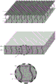
In fig. 6, the hollow bead and aerogel composite insulation board of the three-dimensional fabric reinforced framework is shown, the upper small graph is the three-dimensional fabric reinforced framework before the resin is impregnated and the aerogel is filled, the middle small graph is the three-dimensional fabric reinforced framework hollow bead and aerogel composite insulation board tile after the resin is impregnated and the aerogel is filled, and the lower small graph is a partial enlarged view in a dotted line circle of the middle small graph. The process comprises the following steps: 1. weaving a three-dimensional fabric by adopting a three-dimensional weaving technology (two layers of warp and weft yarns are interwoven to form a veil layer x and y, and then the two layers of veil layers are interwoven to bind the two layers of veil layers into a whole by a spacing yarn z), 2, impregnating the three-dimensional fabric by using a diluted glass fiber reinforced plastic resin, curing to form a double-layer breathable fiber resin plate which takes countless spacing yarn resin connecting ribs z' as a support and is connected with the support, 3, preparing an alcosol (the molar ratio of ethyl orthosilicate, absolute ethyl alcohol, deionized water and hydrochloric acid water solution with the mass concentration of 0.1mol/L is 1: 10: 6: 0.012; adjusting the pH of a mixed precursor solution to 3.5, stirring and hydrolyzing for 8 hours at 45 ℃ to fully hydrolyze the mixed precursor solution to obtain sol), 4, carrying out in-situ synthesis of aerogel (the three-dimensional spacing fabric is vertically placed into 100mL of alcosol and cooled to room temperature, dropwise adding 75mL of 0.5mol/L ammonia water solution, and stirring for 3 min; forming alcogel in water bath at 45 ℃ for 10 min. Standing and aging the wet gel in a water bath at 45 ℃ for 8 h; after aging, soaking the alcogel in n-hexane for exchange twice, 6h each time; carrying out surface modification by using a mixed solution of trimethylchlorosilane and n-hexane with the volume fraction of 15% to improve the porosity, and modifying for 24 hours under the water bath condition of 50 ℃; soaking and washing the modified wet gel in normal hexane to remove a surface modifier and other reaction products, and repeatedly rinsing with deionized water for two times; and finally, respectively drying the glass fiber three-dimensional woven spacer fabric filled with the silicon dioxide aerogel for 12 hours at 60 ℃, 80 ℃ and 120 ℃ by adopting a normal pressure gradient drying method, 5. carrying out sand blasting treatment on the surface of the plate tile to remove the aerogel on the surface of the resin plate, 6, brushing air holes on the surface of the hollow microsphere glass fiber reinforced plastic resin closed fiber resin plate on the surface of the plate tile, and curing the resin to obtain the hollow microsphere and aerogel composite heat-insulating plate taking the glass fiber three-dimensional woven spacer fabric filled with the silicon dioxide aerogel as a reinforced framework.
In fig. 7, a structure of a micro-heat tube plate heat dissipation and heat insulation integrated photovoltaic tile suitable for being paved on a roof is shown, a heat insulation layer B is a hollow micro-bead matrix layer, a micro-heat tube plate a is an anodized aluminum alloy hollow flat plate, a large number of micro-groove groups D (in a small edge cut open at the lower left corner in the figure) are arranged in the micro-heat tube plate a in the same direction, working medium E methanol (a corrugated liquid surface in a window at the right side in the figure) is filled in the micro-heat tube plate a, G is a micro-heat tube plate end press seal line, each micro-groove naturally forms a micro-heat tube structure, the hollow micro-bead matrix layer B and a photovoltaic cell C are respectively compounded on two surfaces of the micro-heat tube plate a, the upper end of the micro-heat tube plate a extends to the outside of a plate width of a photovoltaic. Therefore, heat generated by the photovoltaic cell C during operation is transferred to the micro-heating tube plate A, when the temperature of the heated micro-heating tube plate rises to a certain temperature, the working medium E methanol (with the boiling point of 64.7 ℃) in the micro-heating tube plate is changed into a gas state from a liquid state, phase change heat absorption is generated, the temperature of the micro-heating tube plate at the evaporation position is rapidly reduced, the rising gas working medium is changed into a liquid state after being cooled at the top end (provided with the heat dissipation device F) of the micro-heating tube plate, phase change heat dissipation is generated, then the liquid methanol flows back to the bottom of the micro-heating tube plate under the action of gravity, the working medium circularly and repeatedly carries heat to the top of the micro-heating tube. The heat insulation layer B isolates the heat transfer, and the invasion of outdoor heat in summer and the loss of indoor heat in winter are avoided. The heat radiator F in the figure is a water-cooled metal tube with inner fins, the flat surface of the metal tube is tightly attached to the upper end of a micro-heating tube plate extending to the outside of the plate width of the photovoltaic cell panel, when the heat radiator F works, liquid flows through the metal tube, the micro-heating tube is taken away, the liquid is transferred to working media of the heat radiator to generate phase change heat radiation, and then the heat is transferred to water in a roof water tank to provide hot water for residents.
In fig. 8, a phase change energy storage floor 9 with a calandria bag structure is shown, and the biggest problem of the greenhouse building is that when sunlight is sufficient at noon in winter, the outdoor temperature is below zero and over 30 degrees, the indoor temperature is above zero and 10 degrees in the early morning, and the temperature difference between day and night is too large! And adopt the phase change energy storage floor of calandria bagging structure, the high-efficient heat that absorbs midday sunshine makes the temperature in the room be unlikely to overheated to the heat that stores at midday shifts to release evening, makes night, early morning be unlikely to too cold, thereby has solved this problem effectively. When the sunlight is insufficient or the temperature is too low, the electric heating wire h (carbon fiber) is heated to generate heat, and the heat is efficiently transferred to the bagged phase-change material 10 in the calandria in a large area through the metal calandria. The service life of the phase change energy storage material is about ten years, and the calandria bag-packed structure can be conveniently taken out from the side of the building body for replacement.
In fig. 9, in winter, the south-direction window is opened, the ascending air flow enters the room through the adjustable shutter under the wind guiding effect of the heat dissipation and insulation integrated photovoltaic panel shutter 7 and the chimney effect of the solar chimney, then passes through the room to enter the sun-back surface, and then is pumped to the top chimney, so that the building realizes unpowered ventilation. The ventilation can be carried out by adopting a full heat exchange ventilation system in winter. The louver in the drawing is very narrow, has good sun-shading effect in summer and poor heat preservation effect in winter, and is suitable for tropical areas which do not need to be kept warm in winter.
In fig. 10, a building 1 is a steel framework, each layer of metal calandria phase change energy storage floor 9 is paved, bagged phase change materials 10 are installed in the metal calandria phase change energy storage floor 9, a plurality of layers of transparent plates are embedded and wrapped around the periphery (four sides and top) of the framework to completely collect light and floor wall 8, a heat dissipation and insulation integrated photovoltaic plate louver 7 is covered outside the multi-layer transparent plate completely collecting floor wall 8, a side heat collection shed 2 and a top heat collection shed 3 are arranged outside the heat dissipation and insulation integrated photovoltaic plate louver 7 on the four sides and the top of the building 1, the top of the top heat collection shed 3 is connected with a chimney 4, a turbine generator 5 is arranged in the chimney 4, an air inlet 6 is arranged at the bottom of the side heat collection shed 2, an ultrathin sound and light-proof partition wall 11 is a hollow micro-bead laminated core layer double-layer toughened glass partition wall (see fig. 11 in detail) with the replacement of heavy brick wall cement, and reduced daytime illumination of deep rooms. The air garden 12 is built under the top heat dissipation and heat insulation integrated photovoltaic panel shutter, the balcony 13 is also built on the big balcony which can be irradiated by sunlight on each layer, and as the two gardens are in the greenhouse, the garden can be in spring in four seasons even in northern severe cold regions, and the scene that the outdoor part of the cold region withers in winter can not appear. The filter screens can be arranged at the air inlet and the upper opening of the chimney, so that the invasion of dust and mosquitoes and flies is prevented, and the pollution of dust collection and pesticide on the surface of the photovoltaic shutter is reduced. The upper opening of the chimney can be provided with a ventilating top cap which can prevent rain, snow and dust from invading while ventilating.
In fig. 11, a front plate H and a rear plate I in a hollow bead laminated core plate are made of 5 cm frosted toughened glass, hollow beads K in a hollow bead laminated core layer J are made of 45-150 μm hollow glass beads, a piece of laminated explosion-proof sound-proof and heat-insulating glass with the thickness of 11 mm is adhered between the front plate H and the rear plate I by sandwiching the hollow bead laminated core layer J, and a plurality of hollow bead matrix layers in the hollow bead laminated core plate effectively block heat flow and sound conduction entering the plate. The light-weight sound insulation board is thin, light, sound-proof, light-transmitting, heat-insulating, moisture-proof, waterproof, fireproof, decoration-free, scrubbing-resistant, impact-resistant, long in service life, land-saving, environment-friendly, waste-utilizing, convenient to construct and low in cost, and transportation cost is reduced.
The overground part of the building can be completely free of cement which is bricks and tiles, the assembly and the disassembly are quick, all materials can be recycled, almost no construction pollution is caused, no construction waste is generated, no decoration pollution is caused, the energy is basically self-sufficient, and the real green building is realized.
Claims (1)
1. The utility model provides a building body greenhouse building of two electricity generations of photovoltaic tripe and solar chimney, includes building body (1), side thermal-arrest canopy (2), top thermal-arrest canopy (3), chimney (4), turbogenerator (5), air intake (6), thermal-insulated integrative photovoltaic board tripe (7) of heat dissipation, multilayer transparent plate daylighting wall window (8) that fall to the ground, characterized in that entirely: the solar heat collecting and heat insulating integrated wall comprises a building body (1), wherein a side heat collecting shed (2) is arranged on the sunny side of the building body, a top heat collecting shed (3) is arranged at the top of the top heat collecting shed (3), a chimney (4) is connected to the top of the top heat collecting shed (3), a turbine generator (5) is arranged in the chimney (4), an air inlet (6) is arranged at the bottom of the side heat collecting shed (2), heat dissipation and heat insulation integrated photovoltaic panel shutters (7) are arranged in the side heat collecting shed (2) and the top heat collecting shed (3), and a room sunny side of the building body (1.
Priority Applications (1)
| Application Number | Priority Date | Filing Date | Title |
|---|---|---|---|
| CN201922462196.7U CN211776079U (en) | 2019-12-31 | 2019-12-31 | Building body greenhouse building with photovoltaic shutter and solar chimney for double power generation |
Applications Claiming Priority (1)
| Application Number | Priority Date | Filing Date | Title |
|---|---|---|---|
| CN201922462196.7U CN211776079U (en) | 2019-12-31 | 2019-12-31 | Building body greenhouse building with photovoltaic shutter and solar chimney for double power generation |
Publications (1)
| Publication Number | Publication Date |
|---|---|
| CN211776079U true CN211776079U (en) | 2020-10-27 |
Family
ID=72889873
Family Applications (1)
| Application Number | Title | Priority Date | Filing Date |
|---|---|---|---|
| CN201922462196.7U Active CN211776079U (en) | 2019-12-31 | 2019-12-31 | Building body greenhouse building with photovoltaic shutter and solar chimney for double power generation |
Country Status (1)
| Country | Link |
|---|---|
| CN (1) | CN211776079U (en) |
-
2019
- 2019-12-31 CN CN201922462196.7U patent/CN211776079U/en active Active
Similar Documents
| Publication | Publication Date | Title |
|---|---|---|
| CN100547184C (en) | Photovoltaic passive heating wall | |
| CN102787701B (en) | Photovoltaic controllable heat collection wall combined with Hui-style architecture sunshade eaves | |
| CN102776959B (en) | Energy-saving solar energy combined modular split phase-changing house energy-saving system | |
| CN101705751B (en) | Solar energy integration buildinghouse | |
| CN110984625A (en) | Building body greenhouse building with photovoltaic shutter and solar chimney for double power generation | |
| CN201050898Y (en) | Solar air heat-collecting tile | |
| CN106013536A (en) | Trombe curtain wall suitable for subtropical area | |
| CN204494579U (en) | The solar heating integrated with building roof and ventilation energy composite energy system | |
| CN211774865U (en) | Energy-conserving photovoltaic curtain system | |
| CN201874169U (en) | Novel solar heat collection enclosing structure | |
| CN202039451U (en) | Energy-saving and water-saving building | |
| CN1991254A (en) | Refrigerating and heat-producing device utilizing architecture structure as heat exchanger | |
| CN202787558U (en) | Photovoltaic controllable collectorheat-collection wall combined with sunshading eave of Huizhou architecture | |
| CN202300098U (en) | Solar power generation and heat recovery/insulation indoor building energy saving system | |
| CN205224350U (en) | Tripe formula photovoltaic building facade and tripe formula photovoltaic curtain wall | |
| CN211776079U (en) | Building body greenhouse building with photovoltaic shutter and solar chimney for double power generation | |
| CN217460885U (en) | Solar photovoltaic decorative structure and building | |
| CN207960378U (en) | A kind of photovoltaic and photothermal alliance window body component designed based on perception outside architecture indoor | |
| CN208563680U (en) | A kind of architecture-integral photovoltaic and photothermal alliance component based on the design of indoor and outdoor perception | |
| CN202081703U (en) | Energy-saving water-saving building | |
| CN102110733A (en) | Device integrating photovoltaic use with photothermal use of solar energy | |
| CN114622745A (en) | Heat dissipation and heat insulation integrated photovoltaic panel energy storage greenhouse box body | |
| CN108457406A (en) | A kind of architecture-integral photovoltaic and photothermal alliance component based on the design of indoor and outdoor perception | |
| CN110230457A (en) | A kind of photovoltaic and photothermal alliance window body component designed based on perception outside architecture indoor | |
| CN201567806U (en) | Solar energy integration house |
Legal Events
| Date | Code | Title | Description |
|---|---|---|---|
| GR01 | Patent grant | ||
| GR01 | Patent grant |