CN211774865U - Energy-conserving photovoltaic curtain system - Google Patents
Energy-conserving photovoltaic curtain system Download PDFInfo
- Publication number
- CN211774865U CN211774865U CN201921971974.9U CN201921971974U CN211774865U CN 211774865 U CN211774865 U CN 211774865U CN 201921971974 U CN201921971974 U CN 201921971974U CN 211774865 U CN211774865 U CN 211774865U
- Authority
- CN
- China
- Prior art keywords
- photovoltaic
- energy
- curtain wall
- wall body
- curtain
- Prior art date
- Legal status (The legal status is an assumption and is not a legal conclusion. Google has not performed a legal analysis and makes no representation as to the accuracy of the status listed.)
- Active
Links
Images


Classifications
-
- Y—GENERAL TAGGING OF NEW TECHNOLOGICAL DEVELOPMENTS; GENERAL TAGGING OF CROSS-SECTIONAL TECHNOLOGIES SPANNING OVER SEVERAL SECTIONS OF THE IPC; TECHNICAL SUBJECTS COVERED BY FORMER USPC CROSS-REFERENCE ART COLLECTIONS [XRACs] AND DIGESTS
- Y02—TECHNOLOGIES OR APPLICATIONS FOR MITIGATION OR ADAPTATION AGAINST CLIMATE CHANGE
- Y02B—CLIMATE CHANGE MITIGATION TECHNOLOGIES RELATED TO BUILDINGS, e.g. HOUSING, HOUSE APPLIANCES OR RELATED END-USER APPLICATIONS
- Y02B10/00—Integration of renewable energy sources in buildings
- Y02B10/10—Photovoltaic [PV]
-
- Y—GENERAL TAGGING OF NEW TECHNOLOGICAL DEVELOPMENTS; GENERAL TAGGING OF CROSS-SECTIONAL TECHNOLOGIES SPANNING OVER SEVERAL SECTIONS OF THE IPC; TECHNICAL SUBJECTS COVERED BY FORMER USPC CROSS-REFERENCE ART COLLECTIONS [XRACs] AND DIGESTS
- Y02—TECHNOLOGIES OR APPLICATIONS FOR MITIGATION OR ADAPTATION AGAINST CLIMATE CHANGE
- Y02E—REDUCTION OF GREENHOUSE GAS [GHG] EMISSIONS, RELATED TO ENERGY GENERATION, TRANSMISSION OR DISTRIBUTION
- Y02E10/00—Energy generation through renewable energy sources
- Y02E10/50—Photovoltaic [PV] energy
Landscapes
- Load-Bearing And Curtain Walls (AREA)
- Photovoltaic Devices (AREA)
Abstract
The utility model provides an energy-conserving photovoltaic curtain wall system, includes building wall, curtain frame cell and photovoltaic board, and the curtain frame cell is fixed in the wall body outside with self tapping bolt, photovoltaic board and curtain frame cell connection to and the wall body between vacuole formation, the cavity top sets up the air suction pipeline, sets up the fan in the air suction pipeline, and wind has the air outlet through the pipe connection. The utility model discloses utilize the sensitive surface of wall body, furthest must utilize solar energy to realize light and heat and photoelectric conversion. The photovoltaic power generation system has the advantages that the photovoltaic power generation function is met, the requirements of building heating and ventilation are met by effectively utilizing waste heat generated by the photovoltaic panel, resources are saved, and the development trend of current new energy buildings is met.
Description
Technical Field
The utility model relates to a photovoltaic curtain technical field, in particular to energy-conserving photovoltaic curtain system.
Background
With the ever-decreasing consumption of fossil fuels, solar energy has become an important component of energy used by humans and is constantly being developed. Solar energy is used as renewable clean energy and has incomparable superiority with other energy sources. The photovoltaic curtain wall combines the solar power generation technology with the building curtain wall, and the light receiving surface of the building wall is fully utilized to realize photoelectric conversion. Summer is the season of peak power consumption, and is also the period that sunshine volume is the biggest, photovoltaic system generated energy is the most, and photovoltaic curtain wall can play the peak regulation effect to the electric wire netting, can reduce the building energy consumption effectively, promotes society and mankind to get into the era of energy saving pollution abatement.
However, when the existing photovoltaic curtain wall generates electricity under the irradiation of sunlight, the photovoltaic back plate generates a large amount of heat and the temperature rises, which greatly reduces the photoelectric conversion rate and the service life, and leads to the indoor temperature rise in summer.
Disclosure of Invention
For overcoming the deficiencies of the prior art, the utility model aims at providing an energy-conserving photovoltaic curtain wall system, make the temperature of photovoltaic board maintain a lower level, improve the generating efficiency to that partial heat of recycle photovoltaic board temperature rise carries out indoor heating in order to realize energy-conservation.
In order to realize the purpose, the utility model discloses a technical scheme is:
the utility model provides an energy-conserving photovoltaic curtain wall system, includes building wall 1, curtain frame cell 2 and photovoltaic board 3, curtain frame cell 2 sets up in the wall body 1 outside, photovoltaic board 3 is connected with curtain frame cell 2 to and wall body 1 between form cavity 4, 4 tops of cavity set up air suction pipe 5, set up fan 6 in the air suction pipe 5, fan 6 has air outlet 7 through the pipe connection.
The curtain wall frame unit 2 is fixed on the outer side of the wall body 1 through self-tapping bolts.
The photovoltaic panel 3 is preferably a strong, durable, high transparency photovoltaic panel.
The vertical keels and the transverse keels are arranged at equal intervals.
The cavity 4 is a cavity which is through from top to bottom.
And a bypass 8 is arranged on the air suction pipeline 5.
The invention has the beneficial effects that:
compared with the prior art, the utility model discloses utilize the sensitive surface of photovoltaic curtain, realize photovoltaic power generation's function to the waste heat that effectively utilizes the photovoltaic board to produce satisfies the demand of building heating and ventilation. The utility model discloses furthest utilizes solar energy to realize light and heat and photoelectric conversion, and resources are saved accords with the trend of current new forms of energy building development.
Drawings
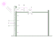
Fig. 1 is a schematic view of an energy-saving photovoltaic curtain wall structure provided by the embodiment of the utility model.
Fig. 2 is an application scene schematic diagram of the photovoltaic curtain wall structure provided by the embodiment of the utility model.
Fig. 3 is an application scene schematic diagram of another structure of the photovoltaic curtain wall provided by the embodiment of the present invention.
Detailed Description
The present invention will be described in further detail with reference to the accompanying drawings.
Referring to fig. 1, the energy-saving photovoltaic curtain wall system comprises a building wall body 1, a curtain wall frame unit 2 and photovoltaic panels 3, wherein the curtain wall frame unit 2 is fixed on the outer side of the wall body 1 through self-tapping bolts, and the photovoltaic panels 3 are connected with the curtain wall frame unit 2 and form a cavity 4 with the wall body 1. The top of the cavity 4 is provided with an air suction pipeline 5, a fan 6 is arranged in the air suction pipeline 5, and the fan 6 is connected with an air outlet 7 through a pipeline.
The structure of the present invention is further explained below with reference to the working principle.
Referring to fig. 2, in winter, under the irradiation of the sun, the photovoltaic panel converts light energy into electric energy for users to use. Outdoor air flows into the cavity 4 through an air inlet at the bottom of the photovoltaic panel, the temperature of the air in the cavity 4 rises due to the large amount of heat generated by the operation of the photovoltaic panel 3, the air rises under the double actions of the fan 6 and the hot pressing, enters the air suction pipeline 5 and is then sent to each indoor space through the air outlet 7. In the process, after the outdoor air absorbs the heat generated by the photovoltaic panel, the outdoor air enters the room through the ventilation system, the indoor heating and ventilation requirements are met, the indoor air quality is improved, and energy is saved.
Referring to fig. 3, in summer, when the outdoor air temperature is higher than the indoor temperature, the valve at the connection of the air duct 5 and the cavity 4 is closed, and the outdoor hot air flows in from the air inlet at the bottom of the cavity 4 and flows out from the air outlet at the upper part, so that the heat cannot enter the indoor. The ventilation interlayer formed by the cavity 4 is beneficial to taking away heat generated by the photovoltaic panel in the flowing process of air, improves the power generation efficiency of the photovoltaic panel and also enables the wall body to achieve the purposes of heat insulation and temperature reduction. When the outdoor air temperature is lower than the indoor temperature, the bypass 8 on the air duct 5 is opened, and the outdoor air is delivered to the indoor space under the action of the fan 6.
Claims (5)
1. An energy-saving photovoltaic curtain wall system is characterized by comprising a building wall body (1), a curtain wall frame unit (2) and a photovoltaic panel (3), wherein the curtain wall frame unit (2) is arranged on the outer side of the wall body (1), the photovoltaic panel (3) is connected with the curtain wall frame unit (2) and forms a cavity (4) with the wall body (1), an air suction pipeline (5) is arranged at the top of the cavity (4), a fan (6) is arranged in the air suction pipeline (5), and the fan (6) is connected with an air outlet (7) through a pipeline;
the curtain wall frame unit (2) is fixed on the outer side of the wall body (1) by self-tapping bolts;
curtain frame unit (2) mainly comprise vertical keel and horizontal fossil fragments, and photovoltaic board (3) are installed on vertical keel.
2. Energy-saving photovoltaic curtain wall system according to claim 1, characterized in that said photovoltaic panels (3) are preferably strong, durable and transparent.
3. The energy-saving photovoltaic curtain wall system as claimed in claim 1, wherein the vertical keels and the transverse keels are arranged at equal intervals.
4. The energy-saving photovoltaic curtain wall system as claimed in claim 1, wherein the cavity (4) is a cavity which is through from top to bottom.
5. The energy-saving photovoltaic curtain wall system as claimed in claim 1, wherein a bypass (8) is arranged on the air suction pipeline (5).
Priority Applications (1)
| Application Number | Priority Date | Filing Date | Title |
|---|---|---|---|
| CN201921971974.9U CN211774865U (en) | 2019-11-15 | 2019-11-15 | Energy-conserving photovoltaic curtain system |
Applications Claiming Priority (1)
| Application Number | Priority Date | Filing Date | Title |
|---|---|---|---|
| CN201921971974.9U CN211774865U (en) | 2019-11-15 | 2019-11-15 | Energy-conserving photovoltaic curtain system |
Publications (1)
| Publication Number | Publication Date |
|---|---|
| CN211774865U true CN211774865U (en) | 2020-10-27 |
Family
ID=72963667
Family Applications (1)
| Application Number | Title | Priority Date | Filing Date |
|---|---|---|---|
| CN201921971974.9U Active CN211774865U (en) | 2019-11-15 | 2019-11-15 | Energy-conserving photovoltaic curtain system |
Country Status (1)
| Country | Link |
|---|---|
| CN (1) | CN211774865U (en) |
Cited By (3)
| Publication number | Priority date | Publication date | Assignee | Title |
|---|---|---|---|---|
| JP2021147965A (en) * | 2020-03-23 | 2021-09-27 | ミサワホーム株式会社 | Photovoltaic generation heat collection system |
| CN113530041A (en) * | 2021-08-26 | 2021-10-22 | 曹黄旭 | Photovoltaic system curtain wall of energy-saving building |
| CN114525871A (en) * | 2022-03-08 | 2022-05-24 | 盐城电力设计院有限公司 | Breathing type photovoltaic curtain wall |
-
2019
- 2019-11-15 CN CN201921971974.9U patent/CN211774865U/en active Active
Cited By (4)
| Publication number | Priority date | Publication date | Assignee | Title |
|---|---|---|---|---|
| JP2021147965A (en) * | 2020-03-23 | 2021-09-27 | ミサワホーム株式会社 | Photovoltaic generation heat collection system |
| JP7296333B2 (en) | 2020-03-23 | 2023-06-22 | ミサワホーム株式会社 | Photovoltaic heat collection system |
| CN113530041A (en) * | 2021-08-26 | 2021-10-22 | 曹黄旭 | Photovoltaic system curtain wall of energy-saving building |
| CN114525871A (en) * | 2022-03-08 | 2022-05-24 | 盐城电力设计院有限公司 | Breathing type photovoltaic curtain wall |
Similar Documents
| Publication | Publication Date | Title |
|---|---|---|
| CN100547184C (en) | Photovoltaic passive heating wall | |
| CN201129040Y (en) | Energy-saving environment-friendly building | |
| CN211774865U (en) | Energy-conserving photovoltaic curtain system | |
| CN204555418U (en) | A kind of wind-light storage hot type cooling heating and power generation system | |
| CN101942892A (en) | Photovoltaic array wind cooling system integrated with building roof | |
| CN106091478A (en) | A kind of photovoltaic curtain wall based on architectural exterior-protecting construction and residual heat pump utilize system | |
| CN205742648U (en) | A kind of solar-powered photovoltaic curtain wall | |
| CN205619578U (en) | Solar water heating system of building | |
| CN110984625A (en) | Building body greenhouse building with photovoltaic shutter and solar chimney for double power generation | |
| CN201628398U (en) | Building solar water heater | |
| CN201754568U (en) | Integral solar heat collecting power generating device | |
| CN203687175U (en) | Solar energy and wind power comprehensive utilization water supply and air-conditioning energy saving system for high-rise buildings | |
| CN210486133U (en) | Solar heating air supply and water supply system located on outer vertical surface of building | |
| CN205783877U (en) | A kind of solar electrical energy generation heating system | |
| CN204460555U (en) | Bus stop Evaporative Cooling Air-conditioning System | |
| CN207990769U (en) | A kind of solar energy heating type heating system | |
| CN205980441U (en) | Photovoltaic curtain wall and waste heat heat pump utilize system based on building envelope | |
| CN215167336U (en) | Natural tile type solar roof with electricity generation, heat supply, ventilation and air exchange functions | |
| CN202024492U (en) | Solar photovoltaic cogeneration application system | |
| CN207184421U (en) | A kind of BIPV system | |
| CN201817985U (en) | Photovoltaic array air cooling system integrated with building roofing | |
| CN112050282A (en) | Intelligent sensing heat recovery solar heating roof system | |
| CN208777493U (en) | A kind of heating Solar wall of combination photovoltaic power generation | |
| CN211776079U (en) | Building body greenhouse building with photovoltaic shutter and solar chimney for double power generation | |
| CN212253028U (en) | Fresh air ventilation system with solar energy supply |
Legal Events
| Date | Code | Title | Description |
|---|---|---|---|
| GR01 | Patent grant | ||
| GR01 | Patent grant |