CN211458027U - Garlic harvester with preposed cutting table - Google Patents
Garlic harvester with preposed cutting table Download PDFInfo
- Publication number
- CN211458027U CN211458027U CN201922433118.4U CN201922433118U CN211458027U CN 211458027 U CN211458027 U CN 211458027U CN 201922433118 U CN201922433118 U CN 201922433118U CN 211458027 U CN211458027 U CN 211458027U
- Authority
- CN
- China
- Prior art keywords
- garlic
- chain
- wheel
- cutting
- transmission
- Prior art date
- Legal status (The legal status is an assumption and is not a legal conclusion. Google has not performed a legal analysis and makes no representation as to the accuracy of the status listed.)
- Expired - Fee Related
Links
Images






Landscapes
- Harvesting Machines For Root Crops (AREA)
Abstract
The utility model relates to a garlic harvester of header forward type, including power device with install the connecting device at the power device front end, install excavating gear on the connecting device, be located the conveyor of excavating gear discharge side and be located the cutting device in excavating gear the place ahead, still install the power transmission device who is connected with excavating gear, conveyor, cutting device transmission on the connecting device. The utility model can effectively complete the digging task of the cut garlic bulbs by vibrating the digging device, and can shake soil during the transportation process and gather together and remove at the tail end; the depth wheel part is provided with depth limiting scales which can be accurately adjusted; the garlic seedling feeding, cutting and throwing-off tasks can be effectively completed, and the missing cutting rate is low; the garlic shoot separating device has the advantages that the garlic shoots are separated through the metal head protector and the protective cover, the garlic shoots are guided and fed through the garlic shoot guiding strips and the garlic shoot guiding belts, the garlic shoots are stirred by the chain II to rotate, the driving quantity is reduced, and the structural arrangement is more convenient.
Description
Technical Field
The utility model relates to the field of agricultural machinery, in particular to a front header type garlic harvester.
Background
The garlic has more than 2000 years of cultivation and planting history in China, and the cultivation history is long, the cultivation area is large, and the yield is high. The garlic planting area is wide in China, the labor intensity is high, however, the garlic harvesting is an agricultural product with strong seasonality, the workload is high, and the garlic harvesting is centralized. At present, garlic harvesting in China is still in a semi-mechanized state, the working efficiency is low, and the labor cost is high. The garlic harvesting machine has the advantages that harvesting time is short, the field working environment is relatively complex, the operation of a new agricultural machine is not skilled, accidents of the garlic harvesting machine which works frequently occur, mechanical harvesting cannot be performed on the condition that garlic falls down due to artificial factors after excessive bolting or natural reasons such as seasons, rainfall and the like, planting agricultural requirements of various places are not uniform, the spacing and the row spacing of planted plants are different, the field adaptability of the garlic harvesting machine is poor due to the various factors, the damage rate and the loss rate are high, and therefore, the garlic harvesting machine which is strong in field adaptability, simple in structure and strong in practicability is developed urgently.
Although the garlic harvesters in the market at present are divided into two types, namely a sectional type garlic harvester and a combined type garlic harvester, the sectional type garlic harvester is relatively simple in structure, but low in working efficiency, poor in field adaptability, free of seedling and whisker cutting functions, poor in harvested garlic quality, high in damage rate and impurity content rate, large in processing requirement in the later period, and high in labor intensity; the garlic combine harvester has a relatively complex structure, agricultural workers are not easy to quickly get on the garlic in a short time, the garlic seedling uprightness requirement is high for a clamping seedling cutting type harvesting mode, and harvesting of lodging garlic cannot be realized.
Disclosure of Invention
In order to solve the problem, the utility model provides a garlic harvester of header forward type can cut field garlic stem rapidly through leading header, and rearmounted excavating gear can dig out the garlic and tremble soil and carry, gathers together the discharge with the garlic at last, and orderly range is on a straight line. The utility model discloses a cutting the seedling earlier, the results mode that the back was excavated, the transmission is reasonable, guarantees to dig with the profile modeling limit for depth, and excavating gear is fixed with the fuselage, and through reasonable connected mode, the vibration excavation operation can not influence the ride comfort that the harvester went. This cutting excavation type's results operation, field adaptability is stronger, and stability is high, and the results operation is synchronous with rearmounted tractor, and is efficient, simple structure, convenient operation, job stabilization has stronger popularization nature.
The utility model discloses a through following technical scheme realizes, provides a garlic harvester of header forward type, include power device and install the connecting device at the power device front end, the last excavating gear of installing of connecting device, the conveyor who is located the excavating gear discharge side and the cutting device who is located the excavating gear the place ahead of being located of connecting device still install the power transmission device who is connected with excavating gear, conveyor, cutting device transmission on the connecting device.
According to the scheme, the garlic harvester has the advantages that the cutting device is arranged in the front, the digging device is arranged in the rear, and the dug garlic is conveyed through the conveying device, so that the garlic is convenient to intensively process; each part is connected with the power device through the connecting device, so that the installation and the maintenance are convenient, and the power device can adopt an agricultural tractor; the garlic harvester receives power through the power transmission device and transmits the power to the digging device, the conveying device and the cutting device, and the digged garlic is conveyed backwards by the conveying device along with the forward advancing of the whole garlic harvester, so that the harvesting operation efficiency is improved.
Preferably, the connecting device comprises a vehicle body connecting frame fixedly connected to the front end of the power device and two oppositely arranged connecting plates I hinged to the vehicle body connecting frame through transverse pin shafts, and the connecting plates I are located in front of the vehicle body connecting frame. This optimized scheme's connecting device passes through the automobile body link and connects at the power device front end, and connecting plate I can rotate around the round pin axle, consequently can adjust each part height of installing on connecting plate I to conveniently excavate the adjustment at degree of depth and buried inclination.
Preferably, the excavating device is a vibration excavating device which comprises a rotating shaft and a plurality of eccentric wheels, wherein the rotating shaft is connected to the two connecting plates I in a shaft connection mode, the eccentric wheels are distributed along the axial direction and fixedly connected with the rotating shaft, a transmission frame is sleeved on each eccentric wheel, and each transmission frame comprises a circular ring sleeved on each eccentric wheel and a transmission rod fixedly connected with the circular ring; the front of the rotating shaft is provided with a connecting rod which is in shaft connection with the two connecting plates I, the connecting rod is fixedly provided with a scraper knife rest which extends downwards and corresponds to each eccentric wheel, the lower part of the scraper knife rest is hinged with a corresponding transmission rod, and the bottom end of the scraper knife rest is fixedly provided with a scraper blade. When the optimized scheme is used, the rotating shaft rotates to drive the eccentric wheel to rotate, and the eccentric wheel drives the circular ring to do eccentric motion when rotating, so that the transmission rod is driven to do reciprocating motion back and forth periodically, the shovel blade rest and the shovel blade are driven to do reciprocating motion around the connecting rod, finally, the function of vibrating soil loosening and excavating is realized, and the device can adapt to complex geological conditions; adopt vibrations excavating gear to excavate the garlic, improved excavation effect and efficiency.
Preferably, a plurality of guide strips fixedly connected with the connecting plate I are arranged behind the shovel blades, and guide channels opposite to the gaps of the adjacent shovel blades are formed between the adjacent guide strips. According to the optimized scheme, the guide strips are arranged, so that the excavated garlic is moved to the conveying device along the guide channel, and the moving directionality of the garlic is improved.
Preferably, the conveying device comprises a conveying belt in transmission connection with the power transmission device and two gathering plates arranged oppositely on the upper surface of the conveying belt, a garlic channel is formed between the two gathering plates, and the distance between the two gathering plates is gradually reduced along the conveying direction. According to the optimized scheme, the excavated garlic is conveyed backwards by utilizing the rotation of the transmission belt, and the garlic on the transmission belt is gathered and guided by utilizing the gathering plate in the conveying process so as to realize the concentrated discharge of the garlic.
Furthermore, the conveyer belt is provided with mesh holes with the size smaller than that of the garlic bulbs. This optimization scheme is through setting up the net hole on the conveyer belt, and in transportation process, the soil that more does benefit to the garlic adhesion drops along with the rotation of conveyer belt to make the soil that drops spill from the net hole, reduced the garlic and carried soil.
Furthermore, the end, with the larger distance, of each of the two gathering plates is hinged to the connecting plate I through a vertical hinge, the two connecting plates I are fixedly connected through a cross beam, and two fixing rods which downwards extend to the side faces, away from the two gathering plates, of the two gathering plates are fixedly arranged on the cross beam. The gathering plates are hinged with the connecting plate I through hinges, so that the included angle between the two gathering plates can be conveniently adjusted, and the garlic is prevented from being blocked when more garlic is used; the fixing rod is arranged and used for limiting the gathering plate to rotate outwards.
As optimization, the device also comprises depth limiting devices positioned on two sides in front of the vibration excavating device, each depth limiting device comprises a square pipe I fixedly connected with the connecting device and a square pipe II penetrating out of the square pipe I, and a locking bolt jacking to the square pipe II is in threaded connection on the side wall of the square pipe I; and a wheel part rotating shaft is fixedly connected to the square tube II, and a depth limiting wheel is installed on the wheel part rotating shaft. This optimization scheme can adjust the operation degree of depth through setting up the dark device of limit, when increaseing, loosens the locking bolt, and II side pipes of increase are stretched out the length of side pipe I, then screw up the locking bolt, when needing to reduce, loosen the locking bolt, reduce II side pipes of side and stretch out the length of side pipe I, then with the locking bolt screw up can.
As optimization, still include the dome of rigid coupling in I upper end in side pipe and the end cover of rigid coupling in II upper ends in side pipe to and pass the dome downwards and with dome threaded connection's crank, set up the through-hole that supplies the crank to pass on the end cover, the rigid coupling has to be located the through-hole below just is greater than the ball of through-hole size on the crank. This optimization scheme when carrying out the operation degree of depth adjustment, rotate the crank can, it is very convenient to operate, utilizes the threaded connection of crank and dome, makes the crank produce the displacement of direction of height, because the ball can't pass through the through-hole on the end cover, therefore square pipe II takes place the displacement of direction of height along with the crank.
Preferably, a graduated scale is fixedly arranged on the outer side face of the square tube II. This optimization scheme is through setting up the scale, and the balance of convenient calibration both sides limit for depth wheel and the demonstration of limit for depth degree regulation result.
As optimization, the cutting device comprises a support frame fixedly connected to the front end of the connecting device and a reciprocating cutting knife arranged on the support frame, and the reciprocating cutting knife is in transmission connection with the power transmission device; still install the chain II that is located reciprocating type cutting knife top and extends along harvester width direction on the support frame, chain II with power transmission device transmission is connected, and the lateral surface of chain II sets firmly dials the tooth. According to the optimized scheme, garlic seedlings are cut through the reciprocating type cutting knife, non-row-aligning harvesting quick cutting is achieved, the chain II rotates to drive the shifting teeth to move, the cut garlic seedlings move to one side of the device in the transverse direction and are discharged, the reciprocating type cutting knife and the chain II share the power transmission device, the structure is simplified, the cutting and the chain rotation are synchronously carried out, and the waste energy consumption is avoided.
Preferably, the support frame is fixedly connected with a plurality of protective covers extending forwards, the protective covers are distributed at intervals along the transverse direction, and garlic shoot channels are formed between adjacent protective covers; the seedling guide device is characterized in that a shifting wheel meshed with shifting teeth of the chain II is connected to the protective cover through a shaft, a belt pulley I is fixedly arranged on a wheel shaft of the shifting wheel, a belt pulley II in transmission connection with the belt pulley I through a guide strip belt is further connected to the protective cover through a shaft, and a plurality of seedling guide rods which extend outwards in the radial direction and are distributed along the circumferential direction are fixedly arranged on the guide strip belt. According to the optimized scheme, the garlic shoot channels are formed through the arranged protective covers, so that the garlic shoots are divided, and the garlic shoots are cut more orderly; the seedling guide rods are driven to move by the rotation of the guide belt, garlic seedlings are fed in a poking manner, and the cutting efficiency is improved; when the garlic seedlings are stirred to one side by the stirring teeth, the stirring wheel is stirred by the stirring teeth of the chain II, and then the belt pulley I and the guide strip belt are driven to rotate, so that the number of the driving devices is reduced, and the structure is more compact and reasonable.
Preferably, a metal protective head is fixedly arranged at the front end of the protective cover, and the front end of the metal protective head is a tip. This optimization scheme protects the safety cover front end through setting up the metal head to set up to most advanced through the front end with the metal head, further improve branch seedling effect.
As optimization, still the rigid coupling has to lead the seedling strip of leading of seedling stick return stroke side on the guard shield, lead the seedling strip and have radian and curved lateral surface and dial tooth place side towards, lead the distance that the seedling strip stretches out the safety cover and be greater than the distance that the seedling stick stretches out the safety cover. The return stroke side in the optimized scheme is that the seedling guide rod winds around the belt pulley I and then faces to one side where garlic seedlings to be cut move, the garlic seedlings are enabled to move on the outer arc surfaces of the seedling guide rods through the seedling guide strips, the garlic seedlings are guided, and meanwhile the garlic seedlings are limited in the front-back direction through the seedling guide strips, so that the garlic seedlings are prevented from being reversely stirred by the seedling guide belt.
As an optimization, a cutting force transmission device in transmission connection with the power transmission device is installed on the support frame, the cutting force transmission device comprises a commutator fixed on the support frame, a gear I fixedly installed on an input shaft of the commutator, and a gear II and an eccentric wheel fixedly installed on an output shaft of the commutator, a roller which is eccentrically arranged with the output shaft of the commutator and is in transmission connection with a reciprocating type cutting knife is coupled on the eccentric wheel, the gear II is connected with a gear III through a chain I, a gear IV is fixedly installed on a wheel shaft of the gear III, and the gear IV is meshed with the chain II and is connected with a chain wheel V through the chain II. The reverser of the optimized scheme can adopt bevel gear engagement for reversing, so that the power transmitted by the harvester can be conveniently received, the structural arrangement is more convenient, one circle center of the gear II and one circle center of the eccentric wheel are coaxially arranged, and when the gear II rotates, the eccentric wheel is driven to rotate, so that the rolling shaft is driven to rotate around the output shaft of the reverser, and the reciprocating cutting action is realized; when the gear II rotates, the chain I drives the gear III to rotate, and then drives the gear IV to rotate, finally drives the chain II to rotate, and realizes power transmission for the chain II.
And preferably, a gear VI is fixedly arranged on a wheel shaft of the gear III, the gear VI is connected with the chain wheel VII through a chain III, the chain III is positioned between the chain II and the reciprocating type cutting knife and is parallel to the chain II, and the outer side surface of the chain III is fixedly provided with shifting teeth. According to the optimized scheme, the chain III is driven to rotate by the rotation of the gear III, so that the garlic seedlings are driven to be stirred by the driving teeth, and the garlic seedlings are stirred simultaneously by the driving teeth on the chain II, and the lodging of the garlic seedlings is reduced.
Preferably, the reciprocating type cutting knife comprises a fixed blade and a locking block which are fixed relative to the support frame, and a movable blade which is in sliding connection with the fixed blade, wherein a locking groove extending along the cutting direction is formed in the locking block, the movable blade is fixedly connected to a movable blade fixing plate which is in sliding connection with the locking groove, a fixer is fixedly arranged on the movable blade fixing plate, a strip-shaped rolling groove extending along the advancing direction of the harvester is formed in the fixer, and a rolling shaft is inserted into the rolling groove. This optimization scheme is through setting up locking piece and locking groove, makes movable blade fixed plate can only follow the left and right sides direction and promptly the width direction of results festival remove, has guaranteed the reliability of cutting, and during the use, the roller bearing drives the fixer and removes along the cutting direction to along the length direction of rolling groove promptly fore-and-aft direction slide in the rolling groove, when the roller bearing rotated along the eccentric wheel, realized the reciprocating motion of movable blade.
The utility model has the advantages that: the digging task of the cut garlic bulbs can be effectively finished through the vibrating digging device, soil is shaken in the transportation process, and the garlic bulbs are gathered and removed at the tail ends; the vehicle body connecting frame and the connecting plate I adopt a pin shaft connecting mode, so that the influence of eccentric vibration on the running smoothness of the whole tractor is avoided; three groups of eccentric wheels of the excavating device have rotation angles which are 180 degrees different from each other, and the excavating shovel alternately moves back and forth to complete the soil loosening and excavating task, so that the excavating efficiency is improved; the depth wheel part is provided with depth limiting scales which can be accurately adjusted; the garlic seedling feeding, cutting and throwing-off tasks can be effectively completed, the efficiency is high, and the missing cutting rate is low; the garlic shoot separating device has the advantages that the garlic shoots are separated through the metal head protector and the protective cover, the garlic shoots are guided and fed through the garlic shoot guiding strips and the garlic shoot guiding belts, the garlic shoots are stirred to one side of the garlic shoot pushing device by the chain II, meanwhile, the stirring wheel is stirred to rotate, the purposes of reducing driving quantity and cost are achieved, and the structural arrangement is more convenient; the power transmission device is ingenious in arrangement, and the whole complex cutting process can be realized only by driving the gear at the right end of the commutator to rotate.
Drawings
FIG. 1 is an isometric view of the overall structure;
FIG. 2 is an isometric view of the cutting device;
FIG. 3 is a left side view of the cutting device;
FIG. 4 is a top view of the cutting device;
FIG. 5 is a rear view of the cutting device;
FIG. 6 is a view showing a structure of a transmission of an eccentric wheel portion;
FIG. 7 is a partial view of the race and holder driving the blade;
FIG. 8 is an enlarged view of a portion of the cutting device;
FIG. 9 is a schematic view of a seedling guide belt structure;
FIG. 10 is a schematic view of the structure of the rice seedling guide bar;
FIG. 11 is an isometric view of the digging implement;
FIG. 12 is a front view of the digging implement;
FIG. 13 is a left side view of the digging implement;
FIG. 14 is a top view of the digging implement;
FIG. 15 is a schematic view of the drive portion of the excavating device;
FIG. 16 is a cross-sectional view I of the digging implement;
FIG. 17 is a cross-sectional view II of the digging implement;
FIG. 18 is a schematic view of a depth stop configuration;
in the figure: 1. the cutting device, 2. digging device, 3. power device, 1001. gear I, 1002. commutator, 1003, gear II, 1004, gear III, 1005, gear IV, 1006, gear V, 1007, gear VI, 1008, gear VII, 1009, eccentric wheel, 1010, rolling shaft 1011, shaft groove 1012, fixer, 1013, moving blade fixing plate, 1014 locking groove, 1015 moving blade, 1016, fixed blade, 1017, fixed blade fixing plate, 1018, fixing nail, 1019, support frame, 1020, 1022I, 1021, chain II, chain III, 1023, metal shifting plate 1024, shifting wheel, 1025, guide belt guard, 1026, pulley I, 1027, pulley II, 1028, base plate, 1029, protective cover, 1030, metal protective head, 1031, bottom frame, 1032, support tube, 1033, guide bar, 1034, I, 1035, protective plate, 1036, protective plate, 1037, IV, 100. power transmission device, 200. The device comprises a connecting device, 300 vibration excavating devices, 400 depth limiting devices, 500 conveying devices, 101 hydraulic motors, 102 connecting frames, 103 fixing plates I and 104 fixing plates II and 105 chain wheels I and 106 chain wheels II and 107 chains I and 108 extending lugs, 109 chain boxes, 110 rotating shafts, 201 vehicle body connecting frames, 202 connecting plates I and 203 connecting plates II and 204 connecting plates III and 205 pin shafts, 206 pins, 207 guide plates, 208 hinges, 209 gathering plates, 210 rotating shaft fixers, 211 metal guide pipe rotating shafts, 212 guide pipe rotating shaft fixers, 213 tightness adjusters, 214 connecting rods, 215 fixing rods, 216 hydraulic rods, 301 eccentric wheels, 302 transmission frames, 303 knife rests, 304 fixing plates, 305 shovel blades, 306 fixing rings I and 307 fixing rings II and 308 guide strips, 309 loose wheel connecting frames, 309 fixing plates, a loose wheel connecting frame, 401. The device comprises a fastening strip, 402 round covers, 403 square tubes I, 404 square tubes II, 405 crank handles, 406 locking bolts, 407 graduated scales, 408 bearings, 409 depth limiting wheels, 410 wheel part rotating shafts, 501 chain wheels III, 502 chain wheels IV, 503 chain wheels V, 504 chain II, 505 metal guide pipe conveyor belts.
Detailed Description
In order to clearly illustrate the technical features of the present solution, the present solution is explained below by referring to fig. 1 to 18 through specific embodiments.
A garlic harvester with a front header comprises a power device 3 and a connecting device 200 arranged at the front end of the power device, wherein an excavating device 2, a conveying device 500 positioned at the discharge side of the excavating device and a cutting device 1 positioned in front of the excavating device are arranged on the connecting device, and the excavating device is a vibrating excavating device 300; the connecting device 200 is also provided with a power transmission device 100 which is in transmission connection with the digging device, the conveying device 500 and the cutting device.
The power device 3 is a common agricultural tractor, is provided with a complete set of hydraulic system, and is respectively connected with the hydraulic rod and the hydraulic motor through a conveying pipeline.
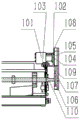
The power transmission device 100 comprises a hydraulic motor 101, a connecting frame 102, a fixing plate I103, a fixing plate II 104, a chain wheel I105, a chain wheel II 106, a chain I107, an extending nose 108, a chain box 109 and a rotating shaft 110. The I105 rotation of output sprocket of hydraulic pump output power drive hydraulic motor 101, through I107 power transmission in chain for sprocket II 106, sprocket II 106 drive concentric pivot 110 and rotate, provide power for vibrations excavating gear. The connecting frame 102 is welded with the frame, the hydraulic motor 101 is fixed through the fixing plate I103 and the fixing plate II 104, the connecting frame 102 is welded with the overhanging nose 108, and the chain box 109 is fixed on the overhanging nose 108.
The connecting device 200 comprises a vehicle body connecting frame 201, a connecting plate I202, a connecting plate II 203, a connecting plate III 204, a pin shaft 205, a pin 206, a guide plate 207, a hinge 208, a gathering plate 209, a rotating shaft fixer 210, a metal guide pipe rotating shaft 211, a guide pipe rotating shaft fixer 212, a tightness regulator 213, a connecting rod 214, a fixing rod 215 and a hydraulic rod 216.
The vehicle body connecting frame 201 is fixedly connected to the front end of the harvester through 6 bolts with different sizes, the harvester can adopt a tractor as a walking machine, and then the vehicle body connecting frame 201 is connected with the front end of the tractor. The connecting plates I202 are two oppositely arranged and are positioned on the two sides in front of the vehicle body connecting frame 201, the two connecting plates I are respectively hinged with the vehicle body connecting frame 201 through transverse pin shafts 205, the tail ends of the pin shafts 205 are locked through pins 206 to prevent the pin shafts 205 from shifting left and right and sliding out, the connecting plates I202, the connecting plates II 203 and the connecting plates III 204 are fixedly connected with each other through bolts, the connecting plates II 203 are positioned at the front ends of the connecting plates I202, a front end for installing limit for depth device, connecting plate III 204 is located connecting plate II 203, a support frame 1019 for rigid coupling cutting device, guide board 207 welds in I202 arc region of connecting plate, pipe pivot fixer 210 passes through the bolt and links to each other with I202 of connecting plate, front end pipe pivot fixer 210, be close to the built-in pipe pivot 211 of pipe pivot fixer 212 in I202 arc region of connecting plate, hinge 208 welds with I202 of connecting plate, overhanging board 209 of gathering together, it passes through dead lever 215 fixed position to gather together board 209.
The vibration excavating device 300 comprises an eccentric wheel 301, a transmission frame 302, a shovel frame 303, a fixing piece 304, a shovel blade 305, a fixing ring I306, a fixing ring II 307, a guide strip 308 and a tension wheel connecting frame 309.
Two ends of the rotating shaft 110 are respectively connected to the two connecting plates I202 in a shaft mode, three eccentric wheels 301 which are distributed along the axial direction are fixedly connected to the rotating shaft 110, and the deviation between the three eccentric wheels is 180 degrees. The eccentric wheel 301 is sleeved with a transmission frame 302, the transmission frame 302 of the embodiment comprises a circular ring sleeved on the eccentric wheel and a transmission rod fixedly connected with the circular ring, and the eccentric wheel 301 rotates to drive the transmission frame 302 to move back and forth. The rotating shaft 110 is also provided with a force transmission gear which is in transmission connection with a gear I1001 in the cutting device through chain transmission.
A connecting rod 214 which is connected with the two connecting plates I202 in a shaft coupling mode is arranged in front of the rotating shaft 110, a scraper frame 303 which extends downwards and corresponds to each eccentric wheel is fixedly arranged on the connecting rod 214, the lower portion of the scraper frame is hinged with a corresponding transmission rod, and a scraper blade is fixedly arranged at the bottom end of the scraper frame. Specifically, the transmission frame 302 is connected with the scraper frame 303 through a bolt, the upper end of the scraper frame 303 penetrates through the connecting rod 214, the left and the right sides of the upper end of the scraper frame 303 are locked by the fixing ring I306, the elastic wheel connecting frame 309 is fixed on the connecting rod 214 through the fixing ring II 307, the fixing plate 304 is installed at the bottom of the scraper frame 303, and the scraper blade 305 is installed above the fixing plate 304. A plurality of guide strips 308 fixedly connected with the connecting plate I202 are arranged behind the shovel blades, and guide channels opposite to the gaps of the adjacent shovel blades are formed between the adjacent guide strips. The eccentric wheel 301 rotates to push the transmission frame 302 to move back and forth, so as to drive the blade frame 302 and the blade 305 to rotate around the connecting rod 214, and thus, the function of soil loosening and digging is realized.
The conveying device 500 comprises a conveying belt in transmission connection with the power transmission device 100 and two oppositely arranged gathering plates 209 positioned on the upper surface of the conveying belt, wherein grid holes smaller than the garlic bulbs in size are formed in the conveying belt. A garlic channel is formed between the two gathering plates, and the distance between the two gathering plates is gradually reduced along the conveying direction. The end with larger distance between the two gathering plates is hinged with the connecting plate I202 through a vertical hinge 208, the two connecting plates I202 are fixedly connected through a cross beam, and two fixing rods 215 which extend downwards to the side faces, which are deviated from the two gathering plates, are fixedly arranged on the cross beam.
Specifically, conveyor 500 includes sprocket III 501, sprocket IV 502, sprocket V503, chain II 504, and metal duct belt 505. The left part of the rotating shaft 110 is provided with a chain wheel III 501 for transmitting power to a seedling cutting device, the right end of the rotating shaft 110 is provided with a chain wheel IV 502, the power is transmitted to a chain wheel V503 through a chain II 504, the chain wheel V503 drives the metal guide pipe conveyor belt 505 to rotate together, wherein 4 metal guide pipe rotating shafts 211 are provided, and the metal guide pipe rotating shaft 211 at the forefront has the function of adjusting the tightness of the metal guide pipe conveyor belt 505. The garlic dug up by the garlic digging device enters the metal guide pipe conveyor belt 505 along the guide strip 308 and the guide plate 207, and in the transportation process, the soil on garlic whiskers and the soil on the digging transmission can be separated and fall off along with the rotation of the metal guide pipe conveyor belt 505 and discharged in the grids of the conveyor belt 505, and the garlic is intensively discharged under the gathering action of the gathering plate 209.
The depth limiting device 400 is located on two sides in front of the vibration excavating device 300, and the depth limiting device 400 comprises a fastening strip 401, a round cover 402, a square tube I403, a square tube II 404, a crank 405, a locking bolt 406, a graduated scale 407, a bearing 408, a depth limiting wheel 409 and a wheel part rotating shaft 410.
The vertical setting of square pipe I403 and fix on connecting plate II 203 through fastening strip 401, and square pipe II 404 wears to establish in square pipe I403, and square pipe I403 is worn out downwards to the lower extreme of square pipe II, and threaded connection pushes up the locking bolt 406 to square pipe II 404 on the lateral wall of square pipe I403, and locking bolt 406 is used for the locking to fix the square pipe II 404 position in square pipe I403. And a graduated scale 407 is fixedly arranged on the outer side surface of the square tube II 404 and is used for calibrating the balance of the depth limiting wheels 409 at the two ends and displaying the depth limiting adjustment result. Square pipe II 404 lower extreme welding level sets up wheel portion pivot 410, install depth wheel 409 through bearing 408 on the wheel portion pivot 410, depth wheel one side is equipped with the boss location, and the opposite side is fixed through the gasket nut. The round cover 402 is welded to I403 upper end of square pipe, and II 404 upper end welding end covers are managed in the side, and the upright part of crank passes round cover 402 downwards and with round cover 402 threaded connection, sets up the through-hole that supplies the crank to pass on the end cover, and the rigid coupling has to be located on the crank the through-hole below just is greater than the ball of through-hole size, prevents that the crank upright part from II 404 roll-offs of side's pipe. The rotation of the crank 405 can be realized, and the square pipe II 404 is driven to move up and down through the internal thread matching with the round hole of the round cover 402, so that the depth limiting operation is realized.
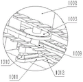
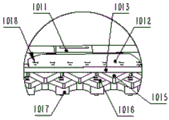
The cutting device 1 comprises a gear I1001, a commutator 1002, a gear II 1003, a gear III 1004, a gear IV 1005, a gear V1006, a gear VI 1007, a gear VII 1008, an eccentric wheel 1009, a roller 1010, a shaft groove 1011, a fixer 1012, a movable blade fixing plate 1013, a locking groove 1014, a movable blade 1015, a fixed blade 1016, a fixed blade fixing plate 1017, a fixing nail 1018, a supporting frame 1019, a chain I1020, a chain II 1021, a chain III 1022, a metal shifting plate 1023, a shifting wheel 1024, a guide belt 1025, a belt pulley I1026, a belt pulley II 1027, a bottom plate 1028, a protective cover 1029, a metal protective head 1030, a bottom frame 1031, a supporting pipe 1032, a seedling guide 1033, a protective plate I1034, a protective plate II 1035, a protective plate III 1036 and a protective plate IV 1037.
The support frame is provided with a cutting force transmission device and a reciprocating type cutting knife which are in transmission connection with the power transmission device, the reciprocating type cutting knife is connected with the cutting force transmission device, and the cutting force transmission device provides power for each part of the cutting device. Still install on the support frame and be located reciprocating type cutting knife top and follow II 1021 of chain that harvester width direction extended, II 1021 of chain with the transmission of cutting power transmission device is connected, and the lateral surface of chain II has set firmly and has dialled tooth 1023, dials tooth 1023 and is the metal plectrum, and II of chain and I1020 of chain are the endless chain, and width direction indicates and the harvester direction of travel vertically transversely.
The reciprocating type cutting knife comprises a fixed blade 1016 and a locking block which are fixedly arranged relative to a supporting frame, and a movable blade 1015 in sliding connection with the fixed blade, wherein a locking groove 1014 extending along the cutting direction is formed in the locking block, the movable blade is fixedly connected to a movable blade fixing plate 1013 in sliding connection with the locking groove, a fixer 1012 is fixedly arranged on the movable blade fixing plate 1013, a strip-shaped rolling groove 1011 extending along the advancing direction of the harvester is fixedly arranged on the fixer, and a rolling shaft 1010 is inserted into the rolling groove 1011. The roller slot 1011 in this embodiment is a straight slot parallel to the advancing direction, and the roller 1010 is inserted into the roller slot 1011 and can rotate back and forth in the roller slot 1011. The rolling slot 1011 is welded with the fixer 1012 into a whole, the fixer 1012 is fixedly connected with the movable blade fixing plate 1013, the movable blade 1015 is fixedly connected below the movable blade fixing plate 1013, and the movable blade fixing plate 1013 is fixedly connected with the movable blade 1015 through the fixing nail 1018.
A plurality of protective covers 1029 extending forwards are fixedly connected to the supporting frame, each protective cover 1029 is distributed at intervals along the transverse direction, garlic shoot channels are formed between adjacent protective covers, a metal head 1030 is fixedly arranged at the front end of each protective cover, and the front end of each metal head is a tip end.
The garlic seedling feeding device is characterized in that a shifting wheel 1024 meshed with the shifting teeth 1023 of the chain II is connected to the protective cover through a shaft, a belt pulley I1026 is fixedly arranged on a wheel shaft of the shifting wheel, a belt pulley II 1027 in transmission connection with the belt pulley I1026 through a guide strip belt 1025 is further connected to the protective cover through a shaft, a plurality of seedling guide rods which extend outwards in the radial direction and are distributed along the circumferential direction are fixedly arranged on the guide strip belt, the seedling guide rods are rubber rods, and the guide strip belt 1025 is provided with rubber rods capable of shifting garlic seedlings to be fed in the periphery compared with a common belt.
Still have through vertical bolt rigid coupling to lead the seedling strip 1033 of leading of seedling stick return stroke side on the guard shield, lead seedling strip 1033 and have the radian and lead the curved lateral surface of seedling strip and dial tooth 1023 place side towards, lead seedling strip place plane level, lead the distance that seedling strip 1033 stretches out the safety cover and be greater than the distance that leads the seedling stick and stretch out the safety cover. The return side of the embodiment is the side of the seedling guide rod moving towards the garlic seedlings to be cut after winding around the belt pulley I.
The cutting force transmission device comprises a commutator 1002 fixed on a support frame, a gear I1001 fixedly mounted on an input shaft of the commutator, a gear II 1003 and an eccentric wheel 1009 fixedly mounted on an output shaft of the commutator, the inside of the commutator is in bevel gear transmission, the eccentric wheel 1009 is positioned below the gear II and welded on the output shaft of the commutator, the gear II 1003 and the eccentric wheel 1009 have a larger circle and a same axle center, the eccentric wheel 1009 is in shaft connection with a roller 1010 extending downwards, the roller 1010 and the eccentric wheel 1009 have a smaller circle and a same axle center, the roller 1010 can rotate freely, and the roller 1010 and the output shaft of the commutator are eccentric and are in transmission connection with a reciprocating type cutting knife. The gear II 1003 is connected with a gear III 1004 through a chain I1020, a gear IV 1005 is fixedly arranged on a wheel axle of the gear III 1004, the gear IV 1005 is meshed with the chain II 1021, and is connected with a chain wheel V1006 through the chain II 1021. The gear II 1003 outputs power to drive the chain wheel set to rotate, the gear III 1004, the gear IV 1005 and the gear VI 1007 are concentric chain wheels, the gear IV 1005 drives the chain wheel V1006 to rotate through the chain II 1021, and the gear VI 1007 drives the chain wheel VII 1008 to rotate through the chain III 1022.
A gear VI 1007 is fixedly mounted on a wheel shaft of the gear III 1004, the gear VI 1007 is connected with a chain wheel VII 1008 through a chain III 1022, the chain III 1022 is located between the chain II 1021 and the reciprocating cutting knife and is parallel to the chain II 1021, and the outer side face of the chain III is fixedly provided with a shifting tooth 1023.
A metal shifting sheet on the chain II 1021 shifts a shifting wheel 1024 to rotate, a belt pulley I1026 is fixed below the shifting wheel 1024, and the belt pulley I1026 is connected with a belt pulley II 1027 through a guide strip belt 1025. The utility model discloses a garlic seedling separating machine, including bottom plate 1028, pulley I1026 and pulley II 1027 coupling, bottom plate 1028 and chassis 1031, stay tube 1032 welds with the cutting body frame 1019, lead seedling strip 1033 through bolted connection on the bottom plate 1028, lead the billet of seedling strip 1033 for having certain radian, bolt adjustable lead the elasticity condition of cooperation between seedling strip 1033 and the bottom plate 1028, thereby adjust and lead the angle between seedling strip 1033 and the bottom plate 1028, realize the garlic seedling drainage effect, prevent that lead strip belt 1025 from shifting garlic seedling reversely, safety cover 1029 is located the top of thumb wheel 1024, the front end of safety cover is equipped with metal head 1030 admittedly, can play the effect of dividing the seedling.
During seedling cutting, power is input to a gear I1001 from a gear on a rotating shaft of the digging device through a long chain in a connecting mode, after the gear I1001 receives the power, the force transmission direction is changed through a commutator 1002, the power is transmitted to a gear II 1003, an eccentric wheel 1009 welded below is driven to rotate along with the rotation of the gear II 1003, so that a roller 1010 is driven to rotate by taking the circle center of a large circle of the eccentric wheel 1009 as the circle center, the roller 1010 is driven downwards to be divided into two parts, one part of the movement is that the roller 1010 moves back and forth in a rolling groove 1011, the other part of the movement is that the roller 1010 drives the rolling groove 1011 to move left and right, a fixer 1012 and a movable blade fixing plate 1013 move left and right, and accordingly the movable blade. The locking block 1014 is connected with a fixed blade fixing plate 1017 through bolts to limit the movable blade 1015 and the movable blade fixing plate 1013 to move left and right, the fixed blade fixing plate 1017 is welded with the cutting main frame 1019, the fixed blade 1016 is arranged on the fixed blade fixing plate 1017 and is connected through a fixing nail 1018, and the movable blade and the fixed blade move relatively to form a reciprocating type cutting knife, so that the movable blade 1015 moves left and right to cut seedlings. The guard plate I1034, the guard plate II 1035, the guard plate III 1036 and the guard plate IV 1037 are connected with the support frame 1019 through bolts. The gear II 1003 drives the chain of the whole set to rotate, wherein metal shifting pieces are arranged on the chain II 1021 and the chain III 1022, garlic seedlings cut off by the shifting pieces are pulled to be discharged from the right side, the shifting pieces on the chain II 1021 pull the shifting wheel 1024 to rotate, the shifting wheel 1024 drives the belt pulley I1026 to be arranged below the shifting wheel 1024, the guide belt 1025 is driven to rotate, the guide belt 1025 rotates, the garlic seedlings 1033 are guided to flow, the garlic seedlings are pulled to be fed into the cutting area, and the garlic seedlings after being cut are discharged from the right side under the pulling effect of the metal shifting pieces of the chain. The chain is at the pivoted in-process, and the metal plectrum must can stir the thumb wheel 1024 and rotate through the middle part that the thumb wheel 1024 dialled the tooth, and the conveying is normally stirred at upper and lower plectrum to the garlic seedling after the shearing, can not influence the plectrum and stir the thumb wheel effect, and the moving speed of plectrum is fast, is convenient for in time derive the garlic seedling.
Before the harvesting machine works, the height of the depth limiting wheel of the digging device is adjusted, so that the overall working height of the garlic harvesting machine is adjusted, including the cutting height and digging depth of garlic seedlings; adjusting parts such as a fixing ring I of the excavating device, and adjusting the soil-entering inclination angle of the excavating shovel. When the harvesting machine works, garlic seedlings are guided into the cutting device under the matching of the guide belt and the seedling guide strips of the cutting device, under the matching action of the movable blade and the fixed blade, the garlic seedlings are cut orderly, and the garlic seedlings are thrown away from the right side under the stirring action of the chain metal shifting piece, so that the garlic seedlings are conveniently centralized. The garlic left in the soil is subjected to soil loosening and digging operation under the action of the vibrating digging device of the digging device, the garlic in the field can be guided into the conveying device, the soil can fall off along with the rotation of the metal guide pipe conveying belt in the conveying process, and under the gathering action of the gathering plate, the garlic after harvesting operation is linearly and orderly arranged in the field, so that the garlic can be conveniently collected and processed in the later period.
The harvester of the embodiment can efficiently complete the functions of cutting seedlings, throwing the seedlings, digging in limited depth, shaking soil, transporting and the like; the garlic seedling feeding, cutting and throwing-off tasks can be effectively completed, the efficiency is high, and the missing cutting rate is low; the digging task of the cut garlic bulbs can be effectively finished, soil is shaken in the transportation process, and the garlic bulbs are gathered at the tail ends and removed; the power device is a common agricultural tractor provided with a complete hydraulic system, can be completed by slightly modifying the original tractor, and is suitable for loading the equipment by most tractors; the connecting frame of the body of the excavating device is connected with the connecting plate I in a pin shaft connection mode, so that the influence of eccentric vibration on the running smoothness of the whole tractor is avoided; three groups of eccentric wheels of the excavating device have rotation angles which are 180 degrees different from each other, and the excavating shovel alternately moves back and forth to complete a soil loosening and excavating task; the depth limiting parts are provided with depth limiting graduated scales, and the depth limiting height can be accurately adjusted.
Of course, the above description is not limited to the above examples, and technical features of the present invention that are not described in the present application may be implemented by or using the prior art, and are not described herein again; the above embodiments and drawings are only used for illustrating the technical solutions of the present invention and are not intended to limit the present invention, and the present invention has been described in detail with reference to the preferred embodiments, and those skilled in the art should understand that changes, modifications, additions or substitutions made by those skilled in the art within the spirit of the present invention should also belong to the protection scope of the claims of the present invention.
Claims (10)
1. A garlic harvester with a front header is characterized in that: comprises a power device (3) and a connecting device (200) arranged at the front end of the power device, wherein the connecting device is provided with an excavating device (2), a conveying device (500) positioned at the discharge side of the excavating device and a cutting device (1) positioned in front of the excavating device,
the connecting device (200) is also provided with a power transmission device (100) which is in transmission connection with the digging device, the conveying device (500) and the cutting device.
2. A garlic harvester with a front header according to claim 1, wherein: the connecting device (200) comprises a vehicle body connecting frame (201) fixedly connected to the front end of the power device and two opposite connecting plates I (202) hinged to the vehicle body connecting frame (201) through a transverse pin shaft (205), and the connecting plates I (202) are located in front of the vehicle body connecting frame (201).
3. A garlic harvester with a front header according to claim 2, wherein: the excavating device (2) is a vibration excavating device (300), the vibration excavating device (300) comprises a rotating shaft (110) which is connected to the two connecting plates I (202) in a shaft connection mode and a plurality of eccentric wheels (301) which are distributed along the axial direction and fixedly connected with the rotating shaft, a transmission frame (302) is sleeved on each eccentric wheel (301), and each transmission frame comprises a circular ring sleeved on each eccentric wheel and a transmission rod fixedly connected with the circular ring;
the front of the rotating shaft (110) is provided with a connecting rod (214) which is in shaft connection with the two connecting plates I (202), the connecting rod (214) is fixedly provided with a scraper knife rest which extends downwards and corresponds to each eccentric wheel, the lower part of the scraper knife rest is hinged with a corresponding transmission rod, and the bottom end of the scraper knife rest is fixedly provided with a scraper knife blade.
4. A garlic harvester with a front header according to claim 2, wherein: the conveying device (500) comprises a conveying belt in transmission connection with the power transmission device (100) and two gathering plates (209) which are arranged on the upper surface of the conveying belt and oppositely arranged, a garlic channel is formed between the two gathering plates, and the distance between the two gathering plates is gradually reduced along the conveying direction.
5. A garlic harvester with a front header according to claim 4, wherein: the conveyer belt is provided with mesh holes with the size smaller than that of the garlic bulbs.
6. A garlic harvester with a front header according to claim 4, wherein: the end, with larger distance, of the two gathering plates is hinged with the connecting plate I (202) through a vertical hinge (208), the two connecting plates I (202) are fixedly connected through a cross beam, and two fixing rods (215) which downwards extend to the side faces, which are deviated from the two gathering plates, are fixedly arranged on the cross beam.
7. A garlic harvester with a front header according to claim 4, wherein: the device comprises a vibration excavating device (300) and depth limiting devices (400) which are arranged on two sides in front of the vibration excavating device, wherein each depth limiting device comprises a square pipe I (403) fixedly connected with a connecting device (200) and a square pipe II (404) penetrating out of the square pipe I (403) downwards, and a locking bolt (406) which is propped against the square pipe II (404) is in threaded connection on the side wall of the square pipe I (403); and a wheel part rotating shaft (410) is fixedly connected to the square tube II (404), and a depth limiting wheel (409) is installed on the wheel part rotating shaft (410).
8. A garlic harvester with a front header according to claim 7, wherein: still include dome (402) and the end cover of rigid coupling in square pipe I (403) upper end in square pipe II (404) upper end of rigid coupling to and pass dome (402) downwards and with dome (402) threaded connection's crank, set up the through-hole that supplies the crank to pass on the end cover, the rigid coupling has and is located on the crank the through-hole below just is greater than the ball of through-hole size.
9. A garlic harvester with a front header according to claim 1, wherein: the cutting device (1) comprises a support frame (1019) fixedly connected to the front end of the connecting device and a reciprocating cutting knife arranged on the support frame, and the reciprocating cutting knife is in transmission connection with the power transmission device; still install chain II (1021) that are located reciprocating type cutting knife top and extend along harvester width direction on the support frame, chain II (1021) with the power transmission device transmission is connected, and the lateral surface of chain II has set firmly and has dialled tooth (1023).
10. A garlic harvester with a front header according to claim 9, wherein: a plurality of protective covers (1029) extending forwards are fixedly connected to the supporting frame, the protective covers (1029) are distributed at intervals along the transverse direction, and garlic shoot channels are formed between adjacent protective covers; the utility model discloses a seedling raising machine, including the chain I, the chain II, the protection cover is last to have a coupling to have dialling wheel (1024) with the dialling tooth (1023) meshing of chain II, the epaxial belt pulley I (1026) that has set firmly of wheel of dialling, still the coupling on the protection cover have through conducting bar belt (1025) with belt pulley I (1026) transmission connection's belt pulley II (1027), set firmly on the conducting bar belt along radial outside extension and along a plurality of seedling bars that lead of circumference distribution.
Priority Applications (1)
| Application Number | Priority Date | Filing Date | Title |
|---|---|---|---|
| CN201922433118.4U CN211458027U (en) | 2019-12-30 | 2019-12-30 | Garlic harvester with preposed cutting table |
Applications Claiming Priority (1)
| Application Number | Priority Date | Filing Date | Title |
|---|---|---|---|
| CN201922433118.4U CN211458027U (en) | 2019-12-30 | 2019-12-30 | Garlic harvester with preposed cutting table |
Publications (1)
| Publication Number | Publication Date |
|---|---|
| CN211458027U true CN211458027U (en) | 2020-09-11 |
Family
ID=72358442
Family Applications (1)
| Application Number | Title | Priority Date | Filing Date |
|---|---|---|---|
| CN201922433118.4U Expired - Fee Related CN211458027U (en) | 2019-12-30 | 2019-12-30 | Garlic harvester with preposed cutting table |
Country Status (1)
| Country | Link |
|---|---|
| CN (1) | CN211458027U (en) |
Cited By (2)
| Publication number | Priority date | Publication date | Assignee | Title |
|---|---|---|---|---|
| CN111937598A (en) * | 2020-09-23 | 2020-11-17 | 黑龙江省农业机械工程科学研究院齐齐哈尔农业机械化研究所 | Onion picking and seedling cutting machine |
| CN114830909A (en) * | 2022-04-20 | 2022-08-02 | 南京农业大学 | Profiling stem-cutting seedling-discharging mechanism of non-row garlic combine harvester |
-
2019
- 2019-12-30 CN CN201922433118.4U patent/CN211458027U/en not_active Expired - Fee Related
Cited By (2)
| Publication number | Priority date | Publication date | Assignee | Title |
|---|---|---|---|---|
| CN111937598A (en) * | 2020-09-23 | 2020-11-17 | 黑龙江省农业机械工程科学研究院齐齐哈尔农业机械化研究所 | Onion picking and seedling cutting machine |
| CN114830909A (en) * | 2022-04-20 | 2022-08-02 | 南京农业大学 | Profiling stem-cutting seedling-discharging mechanism of non-row garlic combine harvester |
Similar Documents
| Publication | Publication Date | Title |
|---|---|---|
| CN211458025U (en) | Garlic head excavating and conveying device of garlic harvester | |
| WO2021092982A1 (en) | Compact potato combine harvester | |
| CN203608555U (en) | Combine harvester for mandulapalka | |
| CN211458027U (en) | Garlic harvester with preposed cutting table | |
| CN105165224A (en) | Small-sized self-propelled garlic combine harvester | |
| CN203340580U (en) | Potato harvester | |
| CN201004807Y (en) | Peanut combine | |
| CN204180488U (en) | Underground corps is sowed, apply fertilizer, spray insecticide, results power drive car | |
| CN102598949A (en) | Potato harvester | |
| CN107318342A (en) | Conveying device and the harvester for rhizome crops using the device | |
| CN201700152U (en) | Chinese yam plant harvest all-in-one machine | |
| CN110786123A (en) | Garlic harvester with residual film recycling function | |
| CN204707482U (en) | A kind of ratio of rhizome medicinal material reaping machine | |
| CN106612876B (en) | Mountain small-sized potato harvesting and seedling-vine separating combined machine | |
| CN210247533U (en) | Traction type rhizoma corydalis harvester | |
| CN104982137B (en) | A kind of mono-track Radix Notoginseng combined harvester | |
| CN204539917U (en) | A kind of block rhizome crop excavating harvester | |
| CN206821261U (en) | A kind of anti-garlic harvester assembly weighed wounded | |
| CN108575253B (en) | Deep rhizome crop harvester | |
| CN109429666B (en) | Segmented green Chinese onion harvester and harvesting method | |
| CN204392851U (en) | The self-propelled carrot combined harvester of duplicate rows | |
| CN204180536U (en) | The hydraulic pressure power-driven system of preposition driving harvester for peanut | |
| CN211580670U (en) | Garlic harvester with residual film recycling function | |
| CN204929638U (en) | Garlic gripping conveyor structure | |
| CN108684252B (en) | Nest planing machine for selenium sand melon |
Legal Events
| Date | Code | Title | Description |
|---|---|---|---|
| GR01 | Patent grant | ||
| GR01 | Patent grant | ||
| CF01 | Termination of patent right due to non-payment of annual fee |
Granted publication date: 20200911 Termination date: 20201230 |
|
| CF01 | Termination of patent right due to non-payment of annual fee |