CN106612876B - A small mountain potato harvesting and seedling and tendril separation combined machine - Google Patents

A small mountain potato harvesting and seedling and tendril separation combined machine Download PDF

Info

Publication number
CN106612876B
CN106612876B CN201710018214.5A CN201710018214A CN106612876B CN 106612876 B CN106612876 B CN 106612876B CN 201710018214 A CN201710018214 A CN 201710018214A CN 106612876 B CN106612876 B CN 106612876B
Authority
CN
China
Prior art keywords
vine
clamping
frame
chain
wheel
Prior art date
Legal status (The legal status is an assumption and is not a legal conclusion. Google has not performed a legal analysis and makes no representation as to the accuracy of the status listed.)
Active
Application number
CN201710018214.5A
Other languages
Chinese (zh)
Other versions
CN106612876A (en
Inventor
杜茂华
莫宁尧
Current Assignee (The listed assignees may be inaccurate. Google has not performed a legal analysis and makes no representation or warranty as to the accuracy of the list.)
Kunming University of Science and Technology
Original Assignee
Kunming University of Science and Technology
Priority date (The priority date is an assumption and is not a legal conclusion. Google has not performed a legal analysis and makes no representation as to the accuracy of the date listed.)
Filing date
Publication date
Application filed by Kunming University of Science and Technology filed Critical Kunming University of Science and Technology
Priority to CN201710018214.5A priority Critical patent/CN106612876B/en
Publication of CN106612876A publication Critical patent/CN106612876A/en
Application granted granted Critical
Publication of CN106612876B publication Critical patent/CN106612876B/en
Active legal-status Critical Current
Anticipated expiration legal-status Critical

Links

Images

Classifications

    • A—HUMAN NECESSITIES
    • A01—AGRICULTURE; FORESTRY; ANIMAL HUSBANDRY; HUNTING; TRAPPING; FISHING
    • A01D—HARVESTING; MOWING
    • A01D27/00—Machines with both topping and lifting mechanisms
    • A01D27/02—Machines with both topping and lifting mechanisms with rigid tools

Landscapes

  • Life Sciences & Earth Sciences (AREA)
  • Environmental Sciences (AREA)
  • Harvesting Machines For Root Crops (AREA)

Abstract

本发明涉及一种山地小型土豆收获及秧蔓分离联合机,属于农业机械设备技术领域。主要包括机架、支撑轮、限深轮装置等,限深轮装置用于保证挖掘铲装置达到适合挖掘深度及达到在地面行走时的适合高度,挖掘铲装置用于将土壤与土豆挖掘翻出地面,输送振动装置用于分离土豆和土,扶蔓装置用于将机械两侧及倒伏的秧蔓准确扶到夹蔓装置;夹蔓装置用于将接收的秧蔓输送给切割装置;蜗轮蜗杆调节装置用于带动夹蔓装置上下调节高度;切割装置用于准确切割夹蔓装置输送过来的秧蔓;传动系统用于为扶蔓装置、夹蔓装置、切割装置、输送振动装置提供传动动力。本发明能够适应复杂山地土豆收获,更好地解决秧蔓缠绕机器的问题,让收获的土豆更干净。
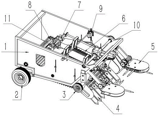
Figure 201710018214

The invention relates to a small mountain potato harvesting and seedling vine separation combined machine, which belongs to the technical field of agricultural machinery and equipment. It mainly includes frame, supporting wheel, depth-limiting wheel device, etc. The depth-limiting wheel device is used to ensure that the excavating shovel device reaches a suitable digging depth and a suitable height when walking on the ground. The excavating shovel device is used to dig out soil and potatoes. On the ground, the conveying vibrating device is used to separate potatoes and soil, and the vine-holding device is used to accurately support the vines and vines on both sides of the machine and the lodging vines to the clamping device; the vine clamping device is used to transport the received vines to the cutting device; the worm gear and worm The adjusting device is used to drive the vine clamping device to adjust the height up and down; the cutting device is used to accurately cut the seedlings and vines delivered by the vine clamping device; the transmission system is used to provide transmission power for the vine holding device, vine clamping device, cutting device, and conveying vibration device. The invention can adapt to potato harvesting in complex mountainous areas, better solve the problem of seedling and tendril winding machines, and make harvested potatoes cleaner.

Figure 201710018214

Description

一种山地小型土豆收获及秧蔓分离联合机A small mountain potato harvesting and seedling and tendril separation combined machine

技术领域technical field

本发明涉及一种山地小型土豆收获及秧蔓分离联合机,特别涉及到土豆收获机械中秧蔓或者杂草对机械缠绕问题的处理,属于农业机械设备技术领域。The invention relates to a small mountain potato harvesting and seedling and vine separation combined machine, in particular to the treatment of the mechanical entanglement of seedlings and weeds in the potato harvesting machine, and belongs to the technical field of agricultural machinery.

背景技术Background technique

土豆机械收获的过程中,需要将土豆秧蔓铲除,并且将土中土豆挖起翻出地面,如果秧蔓或者杂草没有进行事先的处理,很容易造成机器的缠绕和堵塞,影响土豆的正常分离,严重时还会造成机器的损坏,所以挖掘土豆时对秧蔓的处理是很有必要的。目前土豆机械的秧蔓铲除方法主要是运用铲前切除技术,在机械前端设计刀具,对站立秧蔓成段切除,切除的秧蔓料散落在地表,能够解决秧蔓杂草对收获机械的缠绕问题,但存在不足的是散落的秧蔓料与挖出的土豆块混合,对后续的土豆收获以及分类装袋带来更严重的问题;并且土豆秧蔓无法完全切除,更是不能分离出干净的土豆。During the mechanical harvesting of potatoes, it is necessary to remove the potato vines and dig the potatoes out of the ground. If the vines or weeds are not treated in advance, it is easy to cause entanglement and blockage of the machine and affect the normal operation of potatoes. Separation will cause damage to the machine in severe cases, so it is necessary to treat seedlings and vines when digging potatoes. At present, the method of removing seedlings and vines of potato machinery is mainly to use the technology of cutting before the shovel, and design a knife at the front end of the machine to cut off the standing seedlings and vines in sections. problem, but there are deficiencies in that the scattered vines and vines are mixed with the dug out potato pieces, which brings more serious problems to subsequent potato harvesting and sorting and bagging; and the potato vines cannot be completely removed, let alone separated cleanly. potatoes.

发明内容Contents of the invention

本发明要解决的技术问题是提供一种山地小型土豆收获及秧蔓分离联合机,是一种土豆收获机械上秧蔓处理的机械装置,其装置有能够对倒伏的秧蔓进行扶正,实现清除;秧蔓随夹持链25的夹紧被拔起进行输送切除,让土豆块更加干净分离出来;能够自锁的蜗轮蜗杆调节装置9,方便调节,适应山地复杂地形。The technical problem to be solved by the present invention is to provide a small mountain potato harvesting and seedling vine separation machine, which is a mechanical device for treating seedlings and vines on a potato harvesting machine. The seedlings and vines are pulled up with the clamping of the clamping chain 25 for conveying and cutting, allowing the potato pieces to be separated more cleanly; the self-locking worm gear adjustment device 9 is convenient for adjustment and adapts to the complex terrain of the mountain.

本发明采用的技术方案是:一种山地小型土豆收获及秧蔓分离联合机,包括机架1、支撑轮2、限深轮装置3、挖掘铲装置4、扶蔓装置5、夹蔓装置6、切割装置7、输送振动装置8、蜗轮蜗杆调节装置9、传动系统10、秧蔓入口箱11。The technical solution adopted in the present invention is: a small mountain potato harvesting and seedling vine separation combined machine, including a frame 1, a support wheel 2, a depth-limiting wheel device 3, an excavating shovel device 4, a vine holding device 5, and a vine clamping device 6 , cutting device 7, conveying vibration device 8, worm gear adjusting device 9, transmission system 10, seedling vine entrance box 11.

所述的支撑轮2安装在机架1后端,用于带动机械行走;限深轮装置3安装在机架1前端,用于保证挖掘铲装置4达到适合挖掘深度及达到在地面行走时的适合高度;挖掘铲装置4固定在机架1前端,用于将土壤与土豆挖掘翻出地面;输送振动装置8固定在机架1上且安装在挖掘铲装置4后方,输送振动装置8与传动系统10连接,用于分离土豆和土,并将分离出的土豆传送出机械外部;扶蔓装置5固定在机架1前端,用于将机械两侧及倒伏的秧蔓准确扶到夹蔓装置6;夹蔓装置6安装在机架1内部并与蜗轮蜗杆调节装置9连接,用于将接收的秧蔓输送给切割装置7;蜗轮蜗杆调节装置9固定在机架1上端两侧,用于带动夹蔓装置6上下调节高度;切割装置7与夹蔓装置6连接,用于准确切割夹蔓装置6输送过来的秧蔓;传动系统10安装在机架1上,分别与扶蔓装置5、夹蔓装置6、切割装置7、输送振动装置8连接,用于为扶蔓装置5、夹蔓装置6、切割装置7、输送振动装置8提供传动动力,机架1通过连杆与外部拖拉机连接,秧蔓入口箱11安装在夹蔓装置6上且位于切割装置7后端,用于将切割装置7切割后的秧蔓排放到机械外部。The supporting wheel 2 is installed on the rear end of the frame 1 to drive the machine to walk; the depth-limiting wheel device 3 is installed on the front end of the frame 1 to ensure that the excavating shovel device 4 reaches a suitable excavation depth and reaches the height when walking on the ground. Suitable height; the digging shovel device 4 is fixed on the front end of the frame 1, and is used to excavate the soil and potatoes out of the ground; the conveying vibration device 8 is fixed on the frame 1 and installed behind the digging shovel device 4, and the conveying vibration device 8 and the transmission The system 10 is connected to separate the potatoes from the soil, and to send the separated potatoes out of the machine; the vine support device 5 is fixed on the front end of the frame 1, and is used to accurately support the vines and vines on both sides of the machine and the lodging to the vine clamping device 6. The tendril clamping device 6 is installed inside the frame 1 and connected with the worm gear adjusting device 9 for transporting the received seedling tendrils to the cutting device 7; the worm gear adjusting device 9 is fixed on both sides of the upper end of the frame 1 for Drive clamping vine device 6 to adjust height up and down; Cutting device 7 is connected with clamping vine device 6, is used for accurately cutting the seedling vine that clamping vine device 6 conveys; The vine clamping device 6, the cutting device 7, and the conveying vibration device 8 are connected to provide transmission power for the vine holding device 5, the vine clamping device 6, the cutting device 7, and the conveying vibration device 8. The frame 1 is connected to an external tractor through a connecting rod The seedling vine inlet box 11 is installed on the vine clamping device 6 and is located at the rear end of the cutting device 7, and is used for discharging the seedlings and vines cut by the cutting device 7 to the outside of the machine.

具体地,所述的机架1后端设有用于安装支撑轮2轴承的圆孔,机架1两侧靠前处设计有与限深装置相配合连接的竖直方形导轨,其导轨上有两个螺纹孔,使用螺钉压紧可将机架1与限深轮装置3固定连接,挖掘铲装置4通过螺栓固定连接在机架1上,机架1前端设有安装支架,扶蔓装置5通过扶蔓锁紧螺钉13 固定在安装支架上,夹蔓装置6通过夹蔓锁紧螺钉14固定在机架1上,蜗轮蜗杆调节装置9通过螺栓与机架1上的螺纹孔连接。Specifically, the rear end of the frame 1 is provided with a round hole for installing the bearing of the support wheel 2, and the front of both sides of the frame 1 is designed with a vertical square guide rail matched with the depth-limiting device. Two threaded holes, the frame 1 can be fixedly connected with the depth-gauge wheel device 3 by screw compression, the excavating shovel device 4 is fixedly connected to the frame 1 by bolts, the front end of the frame 1 is provided with a mounting bracket, and the tendril device 5 Be fixed on the mounting bracket by supporting the vine locking screw 13, the clamping vine device 6 is fixed on the frame 1 by clamping the vine locking screw 14, and the worm gear adjusting device 9 is connected with the threaded hole on the frame 1 by bolts.

具体地,所述的限深轮装置3包括限深轮及与限深轮连接的限深架12,限深架12安装在机架1的竖直方形导轨里,可上下滑动调节。Specifically, the depth-gauge wheel device 3 includes a depth-gauge wheel and a depth-gauge frame 12 connected to the depth-gauge wheel. The depth-gauge frame 12 is installed in the vertical square guide rail of the frame 1 and can be slid up and down for adjustment.

具体地,所述的挖掘铲装置4包括若干个挖掘铲33,挖掘铲33上设有通孔,挖掘铲33通过穿过通孔的螺栓固定在机架1上。Specifically, the excavating shovel device 4 includes several excavating shovels 33, and through holes are arranged on the excavating shovels 33, and the excavating shovels 33 are fixed on the frame 1 by bolts passing through the through holes.

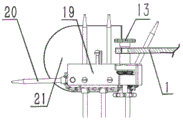
具体地,所述的扶蔓装置5包括扶秧器19、扶指20、扶秧盖21、链条,扶秧器19通过扶蔓锁紧螺钉13连接在机架1上,扶秧盖21通过螺钉固定在扶秧器19上,扶指20固定在扶秧器19内部的扶指链条上,传动链条 29与传动系统10连接并随传动系统10运动,传动链条29将动力传动至扶指链条,扶指20包括左扶指、右扶指,左扶指顺时针随链条同速传动,右扶指逆时针随链条同速传动,将前方秧蔓喂入夹蔓装置6。Specifically, the vine raising device 5 includes a seedling raising device 19, a finger 20, a seedling raising cover 21, and a chain. The seedling raising device 19 is connected to the frame 1 through the vine lifting locking screw 13, and the seedling raising cover 21 passes through the The screw is fixed on the seedling lifter 19, and the finger 20 is fixed on the finger chain inside the seedling lifter 19. The transmission chain 29 is connected with the transmission system 10 and moves with the transmission system 10. The transmission chain 29 transmits power to the finger chain , hold up finger 20 and comprise left hold up finger, right hold up finger, and left hold up finger clockwise with chain transmission at the same speed, right hold up finger anticlockwise with chain at the same speed transmission, the place seedling vine is fed into folder vine device 6.

具体地,所述的夹蔓装置6包括夹持架22、夹持链25、夹蔓链轮24、夹秧盖23,夹持架22两侧的竖立杆与蜗轮蜗杆调节装置9连接,夹蔓链轮24位于夹持架22 上且与传动系统10连接,夹持链25安装在夹蔓链轮24上按转动路径传动,夹持链25包括两侧的链条和中间的链条,两侧的链条逆时针传动,中间的链条顺时针转动,两侧的链条与中间的链条分别对应形成V型夹持口,夹秧盖23通过螺钉固定在夹持架22上,夹持架22两侧有螺纹孔,其与夹蔓锁紧螺钉14配合,将夹蔓装置6固定于机架1上。Specifically, the clamping vine device 6 includes a clamping frame 22, a clamping chain 25, a clamping vine sprocket 24, and a seedling clamping cover 23. The vertical rods on both sides of the clamping frame 22 are connected with the worm gear adjusting device 9, and the clamping The vine sprocket 24 is positioned on the clamping frame 22 and is connected with the transmission system 10. The clamping chain 25 is installed on the clamping vine sprocket 24 and drives according to the rotation path. The clamping chain 25 includes the chain on both sides and the chain in the middle. The chain in the middle is driven counterclockwise, and the chain in the middle rotates clockwise. The chains on both sides and the chain in the middle respectively form a V-shaped clamping opening. The seedling clamping cover 23 is fixed on the clamping frame 22 by screws. There are threaded holes, which cooperate with clamping vine locking screws 14 to fix the clamping vine device 6 on the frame 1 .

具体地,所述的蜗轮蜗杆调节装置9包括齿条30、摇杆34、蜗杆、蜗轮和箱体,摇动摇杆34带动蜗杆转动,蜗杆带动蜗轮运转,蜗轮带动同轴的齿轮一同转动,齿轮带动与其啮合的齿条30滑动而齿条30与夹蔓装置6焊接固定,从而带动夹蔓装置6移动,实现夹蔓装置6的上下调节,箱体上留有螺栓孔,可通过螺栓将其与机架1固定,扭松夹蔓锁紧螺钉14后摇动摇杆34可上下调节蜗轮蜗杆调节装置9。Specifically, the worm gear adjusting device 9 includes a rack 30, a rocking rod 34, a worm, a worm wheel and a casing, the rocking rod 34 drives the worm to rotate, the worm drives the worm to rotate, and the worm drives coaxial gears to rotate together, the gears Drive the rack 30 meshed with it to slide and the rack 30 is welded and fixed with the vine clamping device 6, thereby driving the vine clamping device 6 to move and realize the up and down adjustment of the vine clamping device 6. There are bolt holes on the box body, which can be fixed by bolts. Fixed with the frame 1, the worm gear adjusting device 9 can be adjusted up and down by shaking the rocking bar 34 after loosening the clamp locking screw 14.

具体地,所述的切割装置7包括刀盘31、刀片32、刀轴17、转动轴18,刀盘31位于刀轴17上,刀轴17、转动轴18都位于夹蔓装置6上,夹蔓装置6上设计有支撑刀轴17、转动轴18的轴承,刀轴17与转动轴18间通过斜齿轮啮合传递动力,转动轴18与传动系统(10)间用斜齿轮啮合传递动力。Specifically, the cutting device 7 includes a cutter head 31, a blade 32, a cutter shaft 17, and a rotating shaft 18. The cutter head 31 is located on the cutter shaft 17, and the cutter shaft 17 and the rotating shaft 18 are all located on the clamping device 6. The vine device 6 is designed with bearings supporting the cutter shaft 17 and the rotating shaft 18. The cutter shaft 17 and the rotating shaft 18 transmit power through helical gear engagement, and the rotating shaft 18 and the transmission system (10) transmit power through helical gear engagement.

具体地,所述的传动系统10包括安装在机架1上的万向轴连结器、变速输出的减速器28、可升降传动轴27、中间轴35,万向轴连结器一端连接拖拉机动力源,另一端连接减速器28,减速器28输出轴设有传动到输送振动装置8的链轮及传动到中间轴35的链轮,中间轴35上设有与减速器28上的链轮通过链条传动的链轮、与可升降传动轴27上齿轮啮合的斜齿轮、与扶蔓装置5连接的链轮,可升降传动轴27分别与夹蔓装置6、切割装置7连接,为夹蔓装置6、切割装置7提供动力。Specifically, the transmission system 10 includes a cardan shaft connector installed on the frame 1, a speed reducer 28 for variable speed output, a liftable transmission shaft 27, and an intermediate shaft 35. One end of the cardan shaft connector is connected to the power source of the tractor. , the other end is connected to the reducer 28, the output shaft of the reducer 28 is provided with a sprocket that is transmitted to the conveying vibration device 8 and a sprocket that is transmitted to the intermediate shaft 35, and the intermediate shaft 35 is provided with the sprocket on the reducer 28 through the chain The sprocket wheel of transmission, the helical gear meshed with the upper gear of the liftable drive shaft 27, the sprocket wheel connected with the holding device 5, the liftable drive shaft 27 is connected with the clamping device 6 and the cutting device 7 respectively, which is the clamping device 6 , The cutting device 7 provides power.

本发明收获土豆时机械运作过程为:When the present invention harvests potatoes, the mechanical operation process is:

拖拉机运行后输出动力,通过万向轴连结器传递动力到土豆收获机减速器28,并拖动机械向前运动收获作物,由减速器28输出动力,传动系统10分配动力到相关运动,挖掘铲33将土与作物铲出,随着机械向前运动,土块被挤压到输送振动筛16上,输送振动筛16机械运转,向后输送土块,同时振动轮26带动输送振动筛16振动,使得土与土豆分离,土落入地上,而土豆留在输送振动筛16上向后输送。After the tractor is running, it outputs power, and transmits the power to the potato harvester reducer 28 through the cardan shaft connector, and drives the machine forward to harvest crops. The reducer 28 outputs the power, and the transmission system 10 distributes the power to related movements. The excavation shovel 33. Shovel out the soil and crops. As the machine moves forward, the soil clods are squeezed onto the conveying vibrating screen 16. The conveying vibrating screen 16 is mechanically operated, and the soil clods are conveyed backward. At the same time, the vibrating wheel 26 drives the conveying vibrating screen 16 to vibrate. , so that the soil is separated from the potatoes, the soil falls on the ground, and the potatoes stay on the conveying vibrating screen 16 and are transported backward.

机械装置运行后,放置在收获机械上的秧蔓收割装置随机器同步前进,扶秧器19内左扶指顺时针随链条同速传动,右扶指逆时针随链条同速传动,将前方秧蔓喂入夹持链25的V形口,夹持链25将秧蔓杆夹持输送,过程中输送振动筛16将土豆、泥土以及秧蔓分离,夹持链25将秧蔓整颗夹持输送喂入秧蔓入口箱11,高速旋转的滚刀式饲草切碎刀盘31将喂入的秧蔓切碎,切碎的秧蔓随秧蔓入口箱11下方倾斜通道排放到机器右方田地中,实现肥料回田。After the operation of the mechanical device, the seedling and tendril harvesting device placed on the harvesting machine advances synchronously with the machine. The left hand finger in the seedling lifter 19 is driven clockwise with the chain at the same speed, and the right hand finger is driven counterclockwise with the chain at the same speed, so that the front seedlings are moved forward. The vines are fed into the V-shaped mouth of the clamping chain 25. The clamping chain 25 clamps and transports the vines and vines. Conveying and feeding seedlings and tendrils into the inlet box 11, the hob-type forage chopping cutterhead 31 rotating at high speed chops the fed seedlings and tendrils, and the chopped seedlings and tendrils are discharged to the right of the machine along the inclined passage below the seedlings and tendrils inlet box 11 In the field, the fertilizer is returned to the field.

此机械可挖掘土豆,挖掘部分类似于现有挖掘机械采用挖掘铲进行挖掘,土豆与泥土分离部分采用类似现有土豆收获机械的输送振动筛震动分离机构。This machine can excavate potatoes. The excavating part is similar to the existing excavating machine and uses a digging shovel to excavate. The separating part of potatoes and soil adopts the conveying vibrating screen vibrating separation mechanism similar to the existing potato harvesting machine.

在不工作时,挖掘铲33可通过调节限深轮装置3使挖掘33铲离开地面,从而方便机器运输。When not working, the digging shovel 33 can make the digging 33 shovel leave the ground by adjusting the depth gauge wheel device 3, thereby facilitating machine transportation.

秧蔓分离装置的动力源:通过万向轴连结器将动力传动到减速器28,减速器28输出轴上安装有链轮,通过链条传动到中间轴35,中间轴35上安装有传递动力到扶秧器19的链轮,通过链条传动到扶秧器19,扶秧器19从而工作;中间轴35与可升降传动轴27通过锥齿轮啮合连接,将动力传动到夹蔓装置6的夹蔓链轮24上,夹蔓链轮24带动夹持链25,从而实现夹持链25的运动,夹持输送装置从而工作。The power source of the seedling and tendril separation device: power transmission to the reducer 28 by the cardan shaft connector, a sprocket wheel is installed on the output shaft of the reducer 28, and is transmitted to the intermediate shaft 35 by a chain, and the transmission power to the intermediate shaft 35 is installed on the intermediate shaft 35. The sprocket of the seedling raising device 19 is transmitted to the seedling raising device 19 by a chain, and the seedling raising device 19 works thereby; the intermediate shaft 35 and the liftable transmission shaft 27 are meshed and connected by a bevel gear, and the power transmission is transmitted to the gripping tendril of the gripping device 6. On the sprocket 24, the clamping sprocket 24 drives the clamping chain 25, thereby realizing the movement of the clamping chain 25, and clamping the conveying device to work.

秧蔓切割刀类似现有切草机滚刀式饲草机切割刀设计,通过左侧可升降传动轴27上安装的锥齿轮,锥齿轮啮合方式传递到转动轴18,转动轴18与带动刀盘31的刀轴17通过锥齿啮合传递动力,设置合理传动比满足秧蔓切割刀的切割速度,切割装置7从而工作。Seedling vine cutting knife is similar to the design of existing lawn cutter hob type forage machine cutting knife, through the bevel gear installed on the left side liftable transmission shaft 27, the bevel gear meshing mode is transmitted to the rotating shaft 18, and the rotating shaft 18 and the driving knife The cutter shaft 17 of the disc 31 transmits power through the bevel gear engagement, and a reasonable transmission ratio is set to meet the cutting speed of the seedling and tendril cutting knife, so that the cutting device 7 works.

本发明的有益效果是:The beneficial effects of the present invention are:

(1)拥有扶蔓装置,减少倒伏秧蔓清除的遗漏。(1) Equipped with a vine support device to reduce the omission of lodging seedlings and vines.

(2)蜗轮蜗杆调节装置可形成自锁,可根据土豆秧蔓高矮不同进行调节,能够适应复杂山地土豆收获。(2) The worm gear adjustment device can form a self-locking mechanism, which can be adjusted according to the height of potato seedlings and vines, and can adapt to complex mountainous potato harvesting.

(3)该装置可以实现整颗秧蔓切除处理,更好解决秧蔓缠绕机器问题。(3) The device can realize the cutting of the whole seedling and tendril, and better solve the problem of seedling tendril winding machine.

(4)切碎的秧料排放到机器外,让土豆分离更干净。对后续山地小型土豆收获机实现分拣功能机械的研发提供更好条件。(4) The shredded seedling material is discharged out of the machine, so that the potatoes can be separated more cleanly. It provides better conditions for the research and development of the follow-up small mountain potato harvester to realize the sorting function.

(5)机械装置结构简单、紧凑,方便维护,可靠性强。(5) The structure of the mechanical device is simple and compact, easy to maintain and highly reliable.

附图说明Description of drawings

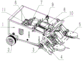
图1 为本发明的整体结构示意图;Fig. 1 is the overall structure schematic diagram of the present invention;

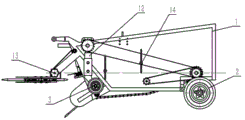
图2为本发明装配主视图;Fig. 2 is the assembly front view of the present invention;

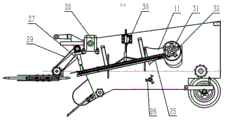
图3 为本发明装配左视图;Fig. 3 is the assembly left view of the present invention;

图4 为本发明装配俯视图;Fig. 4 is the assembled top view of the present invention;

图5为图3的E-E剖视图;Fig. 5 is the E-E sectional view of Fig. 3;

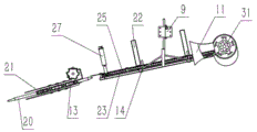
图6为本发明扶蔓装置5、夹蔓装置6、切割装置7、蜗轮蜗杆调节装置9装配俯视图;Fig. 6 is an assembly top view of the tendril holding device 5, the tendril clamping device 6, the cutting device 7, and the worm gear adjusting device 9 of the present invention;

图7为本发明扶蔓装置5、夹蔓装置6、切割装置7、蜗轮蜗杆调节装置9装配主视图;Fig. 7 is an assembly front view of the tendril-holding device 5, the tendril clamping device 6, the cutting device 7, and the worm gear adjusting device 9 of the present invention;

图8为夹蔓装置6与机架1连接图;Fig. 8 is a connection diagram between the clamping device 6 and the frame 1;

图9为扶蔓装置5与机架1连接图。Fig. 9 is a connection diagram between the tendril device 5 and the frame 1.

图中各标号为:1-机架, 2-支撑轮,3-限深轮装置,4-挖掘铲装置,5-扶蔓装置,6-夹蔓装置,7-切割装置,8-输送振动装置,9-蜗轮蜗杆调节装置,10-传动系统,11-秧蔓入口箱,12-限深架,13-扶蔓锁紧螺钉,14-夹蔓锁紧螺钉,15-输送筛主动轮,16-输送振动筛17-刀轴,18-转动轴,19-扶秧器,20-扶指,21-扶秧盖,22-夹持架,23-夹秧盖,24-夹蔓链轮,25-夹持链,26-振动轮,27-可升降传动轴,28-减速器,29-传动链条,30-齿条,31-刀盘,32-刀片,33-挖掘铲,34-摇杆,35-中间轴。The labels in the figure are: 1-frame, 2-supporting wheel, 3-deep-limiting wheel device, 4-excavating shovel device, 5-climbing device, 6-climbing device, 7-cutting device, 8-transporting vibration Device, 9-worm gear adjusting device, 10-transmission system, 11-seeding vine entrance box, 12-depth limit frame, 13-fu vine locking screw, 14-clip vine locking screw, 15-conveyor screen driving wheel, 16-conveying vibrating screen 17-knife shaft, 18-rotating shaft, 19-holding device, 20-supporting finger, 21-holding cover, 22-clamping frame, 23-clamping cover, 24-climbing sprocket , 25-clamping chain, 26-vibrating wheel, 27-liftable transmission shaft, 28-reducer, 29-transmission chain, 30-rack, 31-cutter, 32-blade, 33-excavation shovel, 34- rocker, 35-intermediate shaft.

具体实施方式Detailed ways

下面结合附图和具体实施方式,对本发明作进一步说明。The present invention will be further described below in conjunction with the accompanying drawings and specific embodiments.

实施例1:如图1-9所示,一种山地小型土豆收获及秧蔓分离联合机,包括机架1、支撑轮2、限深轮装置3、挖掘铲装置4、扶蔓装置5、夹蔓装置6、切割装置7、输送振动装置8、蜗轮蜗杆调节装置9、传动系统10、秧蔓入口箱11。Embodiment 1: As shown in Figures 1-9, a small-scale mountain potato harvesting and seedling vine separation combined machine includes a frame 1, a support wheel 2, a depth-limiting wheel device 3, an excavating shovel device 4, a vine-holding device 5, Clamping device 6, cutting device 7, conveying vibration device 8, worm gear adjusting device 9, transmission system 10, seedling vine inlet box 11.

所述的支撑轮2安装在机架1后端,用于带动机械行走;限深轮装置3安装在机架1前端,用于保证挖掘铲装置4达到适合挖掘深度及达到在地面行走时的适合高度;挖掘铲装置4固定在机架1前端,用于将土壤与土豆挖掘翻出地面;输送振动装置8固定在机架1上且安装在挖掘铲装置4后方,输送振动装置8与传动系统10连接,用于分离土豆和土,并将分离出的土豆传送出机械外部;扶蔓装置5固定在机架1前端,用于将机械两侧及倒伏的秧蔓准确扶到夹蔓装置6,即夹持链25的V口;夹蔓装置6安装在机架1内部并与蜗轮蜗杆调节装置9连接,用于将接收的秧蔓输送给切割装置7;蜗轮蜗杆调节装置9固定在机架1上端两侧,用于带动夹蔓装置6上下调节高度;切割装置7与夹蔓装置6连接,用于准确切割夹蔓装置6输送过来的秧蔓;传动系统10安装在机架1上,分别与扶蔓装置5、夹蔓装置6、切割装置7、输送振动装置8连接,用于为扶蔓装置5、夹蔓装置6、切割装置7、输送振动装置8提供传动动力,机架1通过连杆与外部拖拉机连接,秧蔓入口箱11安装在夹蔓装置6上且位于切割装置7后端,用于将切割装置7切割后的秧蔓排放到机械外部。The supporting wheel 2 is installed on the rear end of the frame 1 to drive the machine to walk; the depth-limiting wheel device 3 is installed on the front end of the frame 1 to ensure that the excavating shovel device 4 reaches a suitable excavation depth and reaches the height when walking on the ground. Suitable height; the digging shovel device 4 is fixed on the front end of the frame 1, and is used to excavate the soil and potatoes out of the ground; the conveying vibration device 8 is fixed on the frame 1 and installed behind the digging shovel device 4, and the conveying vibration device 8 and the transmission The system 10 is connected to separate the potatoes from the soil, and to send the separated potatoes out of the machine; the vine support device 5 is fixed on the front end of the frame 1, and is used to accurately support the vines and vines on both sides of the machine and the lodging to the vine clamping device 6, that is, the V port of the clamping chain 25; the vine clamping device 6 is installed inside the frame 1 and connected with the worm gear and worm adjustment device 9, and is used to transport the received seedlings and vines to the cutting device 7; the worm gear and worm adjustment device 9 is fixed on Both sides of the upper end of the frame 1 are used to drive the vine clamping device 6 to adjust the height up and down; the cutting device 7 is connected to the vine clamping device 6 for accurately cutting the seedlings and vines delivered by the vine clamping device 6; the transmission system 10 is installed on the frame 1 are respectively connected with the vine-holding device 5, the vine-clamping device 6, the cutting device 7, and the conveying vibration device 8, and are used to provide transmission power for the vine-holding device 5, the vine-clamping device 6, the cutting device 7, and the conveying vibration device 8. The frame 1 is connected with an external tractor through a connecting rod, and the seedling and tendril inlet box 11 is installed on the gripping device 6 and is located at the rear end of the cutting device 7, and is used for discharging the seedlings and tendrils cut by the cutting device 7 to the outside of the machine.

进一步地,所述的机架1后端设有用于安装支撑轮2轴承的圆孔,机架1两侧靠前处设计有与限深轮装置3相配合连接的竖直方形导轨,其导轨上有两个螺纹孔,使用螺钉压紧可将机架1与限深轮装置3固定连接,挖掘铲装置4通过螺栓固定在机架1上,机架1前端设有安装支架,扶蔓装置5通过扶蔓锁紧螺钉13固定在安装支架上,夹蔓装置6通过夹蔓锁紧螺钉14固定在机架1上,具体地,夹持架左右两端设计有螺纹孔,通过夹蔓锁紧螺钉14将夹持架22固定在机架1内,夹蔓装置6固定连接在机架1内部。蜗轮蜗杆调节装置9通过螺栓与机架1上的螺纹孔连接,其齿条30下端夹持架22焊接,摇动摇杆34,齿条30上下滑动,带动夹蔓装置6上下调节,切割装置7通过轴承座与夹蔓装置6的夹持架22相连接,跟随夹蔓装置6一起移动,准确切割夹蔓装置6输送过来的秧蔓。Further, the rear end of the frame 1 is provided with a round hole for installing the bearing of the support wheel 2, and the front of both sides of the frame 1 is designed with a vertical square guide rail matched with the depth-limiting wheel device 3, and the guide rail There are two threaded holes on it, and the frame 1 can be fixedly connected with the depth-limiting wheel device 3 by pressing with screws. The excavating shovel device 4 is fixed on the frame 1 by bolts. 5 is fixed on the mounting bracket by the vine locking screws 13, and the vine clamping device 6 is fixed on the frame 1 by the vine clamping screws 14. Specifically, threaded holes are designed at the left and right ends of the clamping frame, and the vine clamping device 6 is fixed on the frame 1 by the vine clamping lock screws 14. Tightening screws 14 fix the clamping frame 22 in the frame 1 , and the clamping device 6 is fixedly connected inside the frame 1 . The worm gear adjusting device 9 is connected with the threaded hole on the frame 1 by bolts, the clamping frame 22 at the lower end of the rack 30 is welded, the rocker 34 is shaken, the rack 30 slides up and down, and the clamping device 6 is driven to adjust up and down, and the cutting device 7 The bearing seat is connected with the clamping frame 22 of the vine clamping device 6 and moves together with the vine clamping device 6 to accurately cut the seedlings and vines delivered by the vine clamping device 6 .

进一步地,所述的限深轮装置3包括限深轮及与限深轮连接的限深架12,限深架12安装在机架1的竖直方形导轨里,可上下滑动调节。Further, the depth-gauge wheel device 3 includes a depth-gauge wheel and a depth-gauge frame 12 connected with the depth-gauge wheel. The depth-gauge frame 12 is installed in the vertical square guide rail of the frame 1 and can be slid up and down for adjustment.

进一步地,所述的挖掘铲装置4包括若干个挖掘铲33,挖掘铲33上设有通孔,挖掘铲33通过穿过通孔的螺栓固定在机架1上,本实施例中,共有挖掘铲8个,每个挖掘铲有3个通孔,通过螺栓连接固定在机架1上。Further, the excavating shovel device 4 includes several excavating shovels 33, the excavating shovels 33 are provided with through holes, and the excavating shovels 33 are fixed on the frame 1 by bolts passing through the through holes. There are 8 shovels, each excavating shovel has 3 through holes, and is fixed on the frame 1 through bolt connection.

进一步地,所述的扶蔓装置5包括扶秧器19、扶指20、扶秧盖21、链条,扶秧器19通过扶蔓锁紧螺钉13连接在机架1上,扶秧盖21通过螺钉固定在扶秧器19上,扶指20固定在扶秧器19内部的扶指链条上,传动链条29与传动系统10连接并随传动系统10运动,传动链条29将动力传动至扶指链条,具体地,扶蔓装置5上有一对斜齿轮啮合,扶蔓装置5的斜齿轮主动轮与传动链条29的从动轮同轴,扶蔓装置5的斜齿轮从动轮与扶指链条的主动链轮同轴,传动链条29为此能将动力从中间轴35传动到扶指链条上,扶蔓装置获得动力从而工作。扶指20包括左扶指、右扶指,左扶指顺时针随链条同速传动,右扶指逆时针随链条同速传动,将前方秧蔓喂入夹蔓装置6。Further, the vine raising device 5 includes a seedling raising device 19, a finger 20, a seedling raising cover 21, and a chain. The seedling raising device 19 is connected to the frame 1 through the vine lifting locking screw 13, and the seedling raising cover 21 passes through the The screw is fixed on the seedling lifter 19, and the finger lifter 20 is fixed on the finger lifter chain inside the seedling lifter 19. The transmission chain 29 is connected with the transmission system 10 and moves with the transmission system 10. The drive chain 29 transmits power to the finger lifter chain , specifically, a pair of helical gears are meshed on the vine device 5, the helical gear driving wheel of the vine device 5 is coaxial with the driven wheel of the transmission chain 29, and the driven wheel of the helical gear of the vine device 5 is connected to the driving chain of the finger chain. Wheel coaxial, transmission chain 29 can transfer power from intermediate shaft 35 to the finger chain for this reason, and the vine device obtains power to work thereby. Holding up finger 20 comprises left holding up finger, right holding up finger, and left holding up refers to clockwise transmission with the same speed of chain, and right hand up refers to anticlockwise transmission with chain at the same speed, and the seedling vine in front is fed into clamping vine device 6.

进一步地,所述的夹蔓装置6包括夹持架22、夹秧盖23、夹蔓链轮24、夹持链25,夹持架22两侧的竖立杆与蜗轮蜗杆调节装置9中的齿条30焊接连接,夹蔓链轮24位于夹持架22 上且与传动系统10中可升降传动轴27连接,夹持链25安装在夹蔓链轮24上按转动路径传动,夹持链25包括两侧的链条和中间的链条,两侧链条逆时针传动,中间链条顺时针转动,两侧的链条与中间的链条分别对应形成V型夹持口,夹秧盖23通过螺钉固定在夹持架22上,夹持架22两侧有螺纹孔,其与夹蔓锁紧螺钉14配合,将夹蔓装置6固定于机架1上。Further, the clamping vine device 6 includes a clamping frame 22, a seedling clamping cover 23, a clamping vine sprocket 24, a clamping chain 25, the vertical rods on both sides of the clamping frame 22 and the teeth in the worm and gear adjusting device 9. The bar 30 is welded and connected, the clamping sprocket 24 is located on the clamping frame 22 and is connected with the liftable transmission shaft 27 in the transmission system 10, the clamping chain 25 is installed on the clamping sprocket 24 and is driven by the rotation path, and the clamping chain 25 Including the chains on both sides and the chain in the middle, the chains on both sides drive counterclockwise, the middle chain rotates clockwise, the chains on both sides and the chain in the middle respectively form a V-shaped clamping mouth, and the seedling clamping cover 23 is fixed on the clamping port by screws. On the frame 22 , there are threaded holes on both sides of the clamping frame 22 , which cooperate with the clamping vine locking screws 14 to fix the vine clamping device 6 on the frame 1 .

进一步地,所述的蜗轮蜗杆调节装置9包括齿条30、摇杆34、蜗杆蜗轮和箱体、,摇动摇杆34带动蜗杆转动,蜗杆带动蜗轮运转,蜗轮带动同轴的齿轮一同转动,齿轮带动与其啮合的齿条30滑动,齿条30下端焊接在夹持架22两侧竖立杆上,从而带动夹蔓装置6移动,实现夹蔓装置6的上下调节,箱体上留有孔,如图7所示,本实施例中有6个孔,可通过螺栓将其与机架1固定,扭松夹蔓锁紧螺钉14后摇动摇杆34可上下调节蜗轮蜗杆调节装置9。Further, the worm gear adjustment device 9 includes a rack 30, a rocking rod 34, a worm gear and a casing, the shaking rocking rod 34 drives the worm to rotate, the worm drives the worm to rotate, and the worm drives coaxial gears to rotate together, the gears Drive the tooth bar 30 that meshes with it to slide, and the lower end of the tooth bar 30 is welded on the vertical rods on both sides of the clamping frame 22, thereby driving the clamping device 6 to move, and realizing the up and down adjustment of the clamping device 6. There are holes on the box, such as As shown in Fig. 7, there are 6 holes in this embodiment, which can be fixed with the frame 1 by bolts, and the worm gear adjusting device 9 can be adjusted up and down by shaking the rocker 34 after loosening the clamping screw 14.

土豆的生长受到土壤、地理环境,气候条件等自然环境的影响较大,每个地方的秧蔓的长势都不相同,这给秧蔓处理装置的设计造成困难。本发明采用蜗轮蜗杆调节装置9解决这一问题,该机构连接整个秧蔓夹持切割系统,在扭松夹持切割系统的夹蔓锁紧螺钉14后,摇动蜗轮蜗杆调节装置9的摇杆34可实现升降调节,待调节夹持切割系统到收割秧蔓合适位置后,再扭紧夹蔓锁紧螺钉14即可。这样的设计让山地小型土豆收获机可以适用于恶劣的山地环境。The growth of potatoes is greatly affected by the natural environment such as soil, geographical environment, and climatic conditions. The growth of seedlings and tendrils in each place is different, which causes difficulties in the design of seedling tendril processing devices. The present invention adopts the worm gear adjustment device 9 to solve this problem. This mechanism is connected with the whole seedling and tendril clamping and cutting system. After loosening the clamping and cutting system locking screw 14, shake the rocker 34 of the worm gear adjustment device 9 Can realize lifting adjustment, after the clamping and cutting system is adjusted to the appropriate position for harvesting seedlings and vines, then tighten the clamping and vines locking screw 14 to get final product. This design makes the mountain small potato harvester suitable for harsh mountain environments.

进一步地,所述的切割装置7包括刀轴17、转动轴18、刀盘31、刀片32,刀盘31位于刀轴17上,刀轴17、转动轴18都位于夹蔓装置6上,夹蔓装置6上设计有支撑刀轴17、转动轴18的轴承,刀轴17与转动轴18间通过斜齿轮啮合传递动力,转动轴18与传动系统10中的可升降传动轴27间用斜齿轮啮合传递动力。切割装置7与夹蔓装置6结合在一起,使得两个系统可以一起通过蜗轮蜗杆调节装置9上下调节。切碎的秧蔓随秧蔓入口箱11下方倾斜通道排放到机器右方田地中,实现肥料回田。Further, the cutting device 7 includes a cutter shaft 17, a rotating shaft 18, a cutter head 31, and a blade 32. The cutter head 31 is located on the cutter shaft 17, and the cutter shaft 17 and the rotating shaft 18 are all located on the clamping device 6. The vine device 6 is designed with bearings supporting the cutter shaft 17 and the rotating shaft 18. The power is transmitted between the cutter shaft 17 and the rotating shaft 18 through helical gear engagement, and the helical gear is used between the rotating shaft 18 and the liftable transmission shaft 27 in the transmission system 10. Engagement transmits power. The cutting device 7 is combined with the tendril clamping device 6 so that the two systems can be adjusted up and down through the worm gear adjusting device 9 together. The shredded vines are discharged into the field on the right side of the machine along the inclined passage below the vines inlet box 11, so that the fertilizer can be returned to the field.

进一步地,所述的传动系统10包括安装在机架1上的万向轴连结器、变速输出的减速器28、中间轴35、可升降传动轴27,万向轴连结器一端连接拖拉机动力源,另一端连接减速器28,减速器28输出轴设有传动到输送振动装置8的链轮及传动到中间轴35的链轮,中间轴35上设有与减速器28上的链轮通过链条传动的链轮、与可升降传动轴27上齿轮啮合的斜齿轮、与扶蔓装置5连接的链轮,可升降传动轴27分别与夹蔓装置6、切割装置7连接,为夹蔓装置6、切割装置7提供动力。Further, the transmission system 10 includes a cardan shaft connector installed on the frame 1, a speed reducer 28 for variable speed output, an intermediate shaft 35, and a liftable transmission shaft 27. One end of the cardan shaft connector is connected to the power source of the tractor , the other end is connected to the reducer 28, the output shaft of the reducer 28 is provided with a sprocket that is transmitted to the conveying vibration device 8 and a sprocket that is transmitted to the intermediate shaft 35, and the intermediate shaft 35 is provided with the sprocket on the reducer 28 through the chain The sprocket wheel of transmission, the helical gear meshed with the upper gear of the liftable drive shaft 27, the sprocket wheel connected with the holding device 5, the liftable drive shaft 27 is connected with the clamping device 6 and the cutting device 7 respectively, which is the clamping device 6 , The cutting device 7 provides power.

具体地,所述的万向轴连结器是一根通过扭矩传递运动的轴,中间轴35是一根比较长的齿轮轴,可升降传动轴27,分为两部分,上部分成筒状,安装在机架的轴承上,下部分成捧状,安装在夹蔓装置6的夹蔓链轮24上,其捧插入筒满足伸缩功能,里面就键及键槽满足配合传动功能,本实施例中的可升降传动轴27共4个。Specifically, the cardan shaft connector is a shaft that moves through torque transmission, the intermediate shaft 35 is a relatively long gear shaft, and the transmission shaft 27 can be lifted and divided into two parts, the upper part is cylindrical, Installed on the bearing of the frame, the lower part is formed into a handle, and is installed on the clamping sprocket 24 of the clamping device 6. The inserting tube of the holding handle meets the telescopic function, and the key and the keyway meet the matching transmission function inside. There are totally 4 liftable transmission shafts 27.

力的传动分配通过各级计算分配满足,本发明的设计实现一个主动力源分配整机运动。减速器28输出轴上有2个链轮,分别将力传递到中间轴35和输送振动筛16的运作上,再由中间轴35上4个斜齿轮通过斜齿轮啮合将传动力输出到可升降传动轴27,最终动力分别提供给夹蔓装置6的夹持链25上和切割装置7的转动刀具上。中间轴35上的两个链轮是通过链条传递动力至扶蔓装置5上扶指20运转所需。而整机向前推进由拖拉机通过连杆与机架连接拖动实现。The distribution of force transmission is satisfied by calculation and distribution at various levels, and the design of the invention realizes the distribution of the whole machine movement by an active power source. There are 2 sprockets on the output shaft of the reducer 28, which transmit the force to the intermediate shaft 35 and the operation of the conveying vibrating screen 16 respectively, and then the 4 helical gears on the intermediate shaft 35 output the transmission force to the lifting gear through the meshing of the helical gears. The transmission shaft 27 and the final power are respectively provided to the clamping chain 25 of the clamping device 6 and the rotating cutter of the cutting device 7 . The two sprockets on the intermediate shaft 35 are required for the operation of the finger 20 on the vine device 5 through the transmission of power through the chain. The whole machine is pushed forward by the tractor through the connecting rod and the rack to connect and drag.

本发明的输送振动装置8包括输送振动筛16、输送筛主动轮15、振动轮26,输送振动筛16安装在输送筛主动轮15、振动轮26上,在输送筛主动轮15及振动轮26的带动下转动并且振动,实现土与土豆振动分离功能,输送筛主动轮15及振动轮26通过轴安装在机架1上;通过链条传动方式,将输送筛主动轮、振动轮分别与传动系统连接,获得运动动力,以实现输送振动筛选的功能。Conveying vibration device 8 of the present invention comprises conveying vibrating screen 16, conveying sieve driving wheel 15, vibrating wheel 26, conveying vibrating screen 16 is installed on conveying sieve driving wheel 15, vibrating wheel 26, and conveying sieve driving wheel 15 and vibrating wheel 26 It rotates and vibrates under the driving of the soil to realize the vibration separation function of soil and potatoes. The driving wheel 15 of the conveying screen and the vibrating wheel 26 are installed on the frame 1 through the shaft; Connect to obtain motion power to realize the function of conveying vibration screening.

本发明收获土豆时机械运作过程为:When the present invention harvests potatoes, the mechanical operation process is:

拖拉机运行后输出动力,通过万向轴连结器传递动力到土豆收获机减速器28,并拖动机械向前运动收获作物,由减速器28输出动力,传动系统10分配动力到相关运动,挖掘铲33将土与作物铲出,随着机械向前运动,土块被挤压要输送振动筛16上,输送振动筛16机械运转,向后输送土块,同时振动轮26带动输送振动筛16振动,使得土与土豆分离,土落入地上,而土豆留在输送振动筛16上向后输送。After the tractor is running, it outputs power, and transmits the power to the potato harvester reducer 28 through the cardan shaft connector, and drives the machine forward to harvest crops. The reducer 28 outputs the power, and the transmission system 10 distributes the power to related movements. The excavation shovel 33. Shovel out the soil and crops. As the machine moves forward, the soil clods are squeezed to be transported to the vibrating screen 16. The transporting vibrating screen 16 is mechanically operated, and the soil blocks are transported backwards. At the same time, the vibrating wheel 26 drives the transporting vibrating screen 16 to vibrate , so that the soil is separated from the potatoes, the soil falls on the ground, and the potatoes stay on the conveying vibrating screen 16 and are transported backward.

机械装置运行后,放置在收获机械上的秧蔓收割装置随机器同步前进,扶秧器19内左扶指顺时针随链条同速传动,右扶指逆时针随链条同速传动,将前方秧蔓喂入夹持链25的V口,夹持链25将秧蔓杆夹持输送,过程中输送振动筛16将土豆、泥土以及秧蔓分离,夹持链25将秧蔓整颗夹持输送进入秧蔓入口箱11,高速旋转的滚刀式饲草切碎刀盘31将喂入的秧蔓切碎,切碎的秧蔓随秧蔓入口箱11下方倾斜通道排放到机器右方田地中,实现肥料回田。After the operation of the mechanical device, the seedling and tendril harvesting device placed on the harvesting machine advances synchronously with the machine. The left hand finger in the seedling lifter 19 is driven clockwise with the chain at the same speed, and the right hand finger is driven counterclockwise with the chain at the same speed, so that the front seedlings are moved forward. The vines are fed into the V port of the clamping chain 25, and the clamping chain 25 clamps and transports the vines and vines. During the process, the vibrating screen 16 separates the potatoes, soil and vines and vines, and the clamping chain 25 clamps and transports the whole vines and vines. After entering the seedling inlet box 11, the high-speed rotating hob-type forage grass cutting cutter head 31 chops the fed seedling tendrils, and the chopped seedling tendrils are discharged into the field on the right side of the machine along the inclined passage below the seedling tendril inlet box 11 , to realize the return of fertilizer to the field.

此机械可挖掘土豆,挖掘部分类似于现有挖掘机械采用挖掘铲进行挖掘,土豆与泥土分离部分采用类似现有土豆收获机械的输送振动筛震动分离机构。This machine can excavate potatoes. The excavating part is similar to the existing excavating machine and uses a digging shovel to excavate. The separating part of potatoes and soil adopts the conveying vibrating screen vibrating separation mechanism similar to the existing potato harvesting machine.

在不工作时,挖掘铲33可通过调节限深轮装置3使挖掘铲33离开地面,从而方便机器运输。When not working, the digging shovel 33 can make the digging shovel 33 leave the ground by adjusting the depth gauge wheel device 3, thereby facilitating machine transportation.

夹蔓装置的动力源:通过万向轴连结器将动力传动到减速器28,减速器28输出轴上安装有链轮,通过链条传动到中间轴35,中间轴35上安装有传递动力到扶秧器19的链轮,通过链条传动到扶秧器19,扶秧器19从而工作;中间轴35与可升降传动轴27通过锥齿轮啮合连接,将动力传动到夹蔓装置6的夹蔓链轮24上,夹蔓链轮24带动夹持链25,从而实现夹持链25的运动,夹持输送装置从而工作。The power source of clamping vine device: power is transmitted to speed reducer 28 by cardan shaft connector, and sprocket wheel is installed on the output shaft of speed reducer 28, is transmitted to intermediate shaft 35 by chain, is installed on intermediate shaft 35 and transmits power to propeller. The sprocket of the seedling device 19 is transmitted to the seedling supporter 19 by a chain, and the seedling supporter 19 works thereby; the intermediate shaft 35 and the liftable transmission shaft 27 are meshed and connected by a bevel gear, and the power transmission is transmitted to the clamping vine chain of the clamping vine device 6 On the wheel 24, the clamping sprocket 24 drives the clamping chain 25, thereby realizing the movement of the clamping chain 25, and clamping the conveying device to work.

秧蔓切割刀类似现有切草机滚刀式饲草机切割刀设计,通过左侧可升降传动轴27上安装的锥齿轮,锥齿啮合方式传递到转动轴18,转动轴18与带动刀盘31的刀轴17通过锥齿啮合传递动力,设置合理传动比实现满足秧蔓切割刀的切割速度,切割装置7从而工作。Seedling vine cutting knife is similar to the design of existing lawn cutter hob type forage machine cutting knife, through the bevel gear installed on the left side liftable transmission shaft 27, the bevel gear meshing mode is transmitted to the rotating shaft 18, and the rotating shaft 18 and the driving knife The cutter shaft 17 of the disc 31 transmits power through the bevel gear engagement, and a reasonable transmission ratio is set to meet the cutting speed of the seedling and tendril cutting knife, so that the cutting device 7 works.

以上结合附图对本发明的具体实施方式作了详细说明,但是本发明并不限于上述实施方式,在本领域普通技术人员所具备的知识范围内,还可以在不脱离本发明宗旨的前提下作出各种变化。The specific embodiments of the present invention have been described in detail above in conjunction with the accompanying drawings, but the present invention is not limited to the above embodiments. Variations.

Claims (1)

1. The utility model provides a small-size potato harvesting in mountain region and seedling tendril separation combine which characterized in that: the device comprises a frame (1), a supporting wheel (2), a depth limiting wheel device (3), a digging shovel device (4), a vine supporting device (5), a vine clamping device (6), a cutting device (7), a conveying vibration device (8), a worm gear adjusting device (9), a transmission system (10) and a vine inlet box (11);
the supporting wheel (2) is arranged at the rear end of the frame (1) and is used for driving the mountain small-sized potato harvesting and seedling and vine separating combine to walk; the depth limiting wheel device (3) is arranged at the front end of the frame (1) and used for ensuring that the excavating shovel device (4) reaches an appropriate excavating depth and an appropriate height when walking on the ground; the digging shovel device (4) is fixed at the front end of the frame (1) and is used for digging soil and potatoes to turn out the ground; the conveying vibration device (8) is fixed on the frame (1) and is arranged behind the digging shovel device (4), the conveying vibration device (8) is connected with the transmission system (10) and is used for separating potatoes from soil and conveying the separated potatoes out of the mountain small-sized potato harvesting and seedling-vine separating combine; the vine supporting device (5) is fixed at the front end of the frame (1) and is used for accurately supporting the two sides of the mountain small potato harvesting and vine separating combined machine and the lodged vine to the vine clamping device (6); the vine clamping device (6) is arranged in the frame (1) and connected with the worm and gear adjusting device (9) for conveying the received vine to the cutting device (7); the worm and gear adjusting devices (9) are fixed at two sides of the upper end of the frame (1) and are used for driving the vine clamping device (6) to adjust the height up and down; the cutting device (7) is connected with the vine clamping device (6) and is used for accurately cutting the vine conveyed by the vine clamping device (6); the transmission system (10) is arranged on the frame (1) and is respectively connected with the vine supporting device (5), the vine clamping device (6), the cutting device (7) and the conveying vibration device (8) and used for providing transmission power for the vine supporting device (5), the vine clamping device (6), the cutting device (7) and the conveying vibration device (8), the frame (1) is connected with an external tractor through a connecting rod, the vine inlet box (11) is arranged on the vine clamping device (6) and is positioned at the rear end of the cutting device (7) and used for discharging vine cut by the cutting device (7) to the outside of the mountain small potato harvesting and vine separating combine;
the rear end of the frame (1) is provided with a round hole for installing a bearing of the supporting wheel (2), two sides of the frame (1) are provided with vertical square guide rails which are matched and connected with the depth wheel device (3), the vertical square guide rails are provided with two threaded holes, the frame (1) and the depth wheel device (3) are fixedly connected by using screws, the digging shovel device (4) is fixed on the frame (1) through bolts, the front end of the frame (1) is provided with a mounting bracket, the vine supporting device (5) is fixed on the mounting bracket through a vine supporting locking screw (13), the vine clamping device (6) is fixed on the frame (1) through a vine clamping locking screw (14), and the worm and gear adjusting device (9) is connected with the threaded holes on the frame (1) through bolts;
the depth limiting wheel device (3) comprises a depth limiting wheel and a depth limiting frame (12) connected with the depth limiting wheel, and the depth limiting frame (12) is arranged in a vertical square guide rail of the frame (1) and can be adjusted in an up-down sliding manner;
the digging shovel device (4) comprises a plurality of digging shovels (33), through holes are formed in the digging shovels (33), and the digging shovels (33) are fixed on the frame (1) through bolts penetrating through the through holes;
the vine holding device (5) comprises a seedling holding device (19), a finger (20), a seedling holding cover (21), a finger holding chain and a transmission chain (29), wherein the seedling holding device (19) is connected to the frame (1) through a vine holding locking screw (13), the seedling holding cover (21) is fixed on the seedling holding device (19) through a screw, the finger (20) is fixed on the finger holding chain in the seedling holding device (19), the transmission chain (29) is connected with the transmission system (10) and moves along with the transmission system (10), the transmission chain (29) transmits power to the finger holding chain, the finger holding device (20) comprises a left finger holding device and a right finger holding device, the left finger holding device transmits clockwise along with the chain, the right finger holding device transmits anticlockwise along with the chain at the same speed, and the front vine holding device (6) is fed into the vine holding device;
the vine clamping device (6) comprises a clamping frame (22), a clamping chain (25), vine clamping chain wheels (24) and a vine clamping cover (23), vertical rods on two sides of the clamping frame (22) are connected with a worm and gear adjusting device (9), the vine clamping chain wheels (24) are positioned on the clamping frame (22) and are connected with a transmission system (10), the clamping chain (25) is arranged on the vine clamping chain wheels (24) and is driven according to a rotating path, the clamping chain (25) comprises two chains on two sides and a middle chain, the two chains on two sides are driven anticlockwise, the middle chain rotates clockwise, the two chains on two sides and the middle chain respectively correspond to form a V-shaped clamping opening, the vine clamping cover (23) is fixed on the clamping frame (22) through screws, threaded holes are formed on two sides of the clamping frame (22) and are matched with vine clamping locking screws (14), and the vine clamping device (6) is fixed on a frame (1);
the worm and gear adjusting device (9) comprises a rack (30), a rocker (34), an internal worm, a worm wheel and an external box body, the rocker (34) is rocked to drive the worm to rotate, the worm drives the worm wheel to rotate, the worm wheel drives a coaxial gear to rotate together, the gear drives the rack (30) meshed with the worm wheel to slide, the rack (30) is fixedly welded with the vine clamping device (6), so that the vine clamping device (6) is driven to move, the up-and-down adjustment of the vine clamping device (6) is realized, the box body is provided with a bolt hole, the box body can be fixed with the frame (1) through a bolt, and the worm and gear adjusting device (9) can be adjusted up and down by rocking the rocker (34) after the vine clamping locking screw (14) is loosened;
the cutting device (7) comprises a cutter disc (31), a blade (32), a cutter shaft (17) and a rotating shaft (18), wherein the cutter disc (31) is positioned on the cutter shaft (17), the cutter shaft (17) and the rotating shaft (18) are both positioned on the vine clamping device (6), a bearing for supporting the rotating shaft (18) is designed on the vine clamping device (6), power is transmitted between the cutter shaft (17) and the rotating shaft (18) through helical gear meshing, and power is transmitted between the rotating shaft (18) and the transmission system (10) through helical gear meshing and moves along with the transmission system (10);
the transmission system (10) comprises a universal shaft connector, a speed reducer (30) with variable speed output, a middle shaft (35) and a liftable transmission shaft (27), wherein the universal shaft connector is arranged on a frame (1), one end of the universal shaft connector is connected with a tractor power source, the other end of the universal shaft connector is connected with a speed reducer (28), an output shaft of the speed reducer (28) is provided with a chain wheel for transmitting to a conveying vibration device (8) and a chain wheel for transmitting to the middle shaft (35), the middle shaft (35) is provided with the chain wheel for transmitting with the chain wheel on the speed reducer (28), a bevel gear meshed with a gear on the liftable transmission shaft (27) and a chain wheel connected with a vine clamping device (6) and a cutting device (7), and the liftable transmission shaft (27) is respectively connected with the vine clamping device (6) and the cutting device (7) to provide power for the vine clamping device (7).
CN201710018214.5A 2017-01-11 2017-01-11 A small mountain potato harvesting and seedling and tendril separation combined machine Active CN106612876B (en)

Priority Applications (1)

Application Number Priority Date Filing Date Title
CN201710018214.5A CN106612876B (en) 2017-01-11 2017-01-11 A small mountain potato harvesting and seedling and tendril separation combined machine

Applications Claiming Priority (1)

Application Number Priority Date Filing Date Title
CN201710018214.5A CN106612876B (en) 2017-01-11 2017-01-11 A small mountain potato harvesting and seedling and tendril separation combined machine

Publications (2)

Publication Number Publication Date
CN106612876A CN106612876A (en) 2017-05-10
CN106612876B true CN106612876B (en) 2023-05-12

Family

ID=58842925

Family Applications (1)

Application Number Title Priority Date Filing Date
CN201710018214.5A Active CN106612876B (en) 2017-01-11 2017-01-11 A small mountain potato harvesting and seedling and tendril separation combined machine

Country Status (1)

Country Link
CN (1) CN106612876B (en)

Families Citing this family (4)

* Cited by examiner, † Cited by third party
Publication number Priority date Publication date Assignee Title
CN109360221A (en) * 2018-10-25 2019-02-19 重庆市武隆区农业技术推广中心 A small machine suitable for harvesting potatoes in mountainous areas
CN110663344A (en) * 2019-11-11 2020-01-10 青岛农业大学 A small potato combine harvester
CN112056075B (en) * 2020-09-03 2022-10-18 李向东 Potato harvesting device and control mode thereof
CN115024078A (en) * 2022-06-19 2022-09-09 湖南机电职业技术学院 Polygonatum odoratum combine harvester and harvesting method

Family Cites Families (7)

* Cited by examiner, † Cited by third party
Publication number Priority date Publication date Assignee Title
US1046224A (en) * 1911-09-09 1912-12-03 Peter J Scharbach Potato digger and separator.
CN202172588U (en) * 2011-07-18 2012-03-28 范自富 Potato harvester
CN103814674A (en) * 2013-12-11 2014-05-28 青海林丰农牧机械制造有限公司 Combine harvester matched with four wheels
CN203661582U (en) * 2013-12-23 2014-06-25 吴渭尧 Tuber mustard harvesting, clearing and collecting device
CN204652961U (en) * 2015-03-26 2015-09-23 王占领 The power drive creeper truck of preposition driving underground stem tuber crop harvesting tracked machine
CN106165588B (en) * 2016-07-05 2018-05-29 西南大学 A kind of mustard harvester
CN206564830U (en) * 2017-01-11 2017-10-20 昆明理工大学 A kind of small-sized mountain potato harvest and seedling vine separation combination machine

Also Published As

Publication number Publication date
CN106612876A (en) 2017-05-10

Similar Documents

Publication Publication Date Title
CN102783302B (en) Self walking type garlic combine harvester
CN203708823U (en) Garlic harvesting machine
CN204180488U (en) Underground corps is sowed, apply fertilizer, spray insecticide, results power drive car
CN107771498A (en) A kind of self-propelled garlic digging harvester
CN210987046U (en) A horseshoe harvester
WO2021092982A1 (en) Compact potato combine harvester
CN201004807Y (en) Peanut combine
CN106612876A (en) Mountain land small-size potato harvesting and seedling vine separation combination machine
CN202818956U (en) Potato combine harvester
CN206564830U (en) A kind of small-sized mountain potato harvest and seedling vine separation combination machine
CN201595006U (en) tuber plant harvester
CN206100946U (en) All -in -one that digs up roots is reaped to sugarcane
CN202697236U (en) Self-propelled garlic combine harvester
CN213485770U (en) A kind of agricultural machinery and equipment with the function of fertilizing and weeding
CN103039181B (en) Two ridge four lines peanut combine clamping conveying apparatus for collectings
CN210745905U (en) Straw is smashed and incomplete membrane recovery combined operation all-in-one
KR20180072141A (en) A Bulb crops harvester
CN206728622U (en) One kind residual straw stubble crushing and returning to field machine
CN204180536U (en) The hydraulic pressure power-driven system of preposition driving harvester for peanut
CN103814674A (en) Combine harvester matched with four wheels
US2771728A (en) Root crop harvesting and cutting machine
CN118830388A (en) Intelligent control and adjustment-based traditional Chinese medicine combine harvester and application method thereof
CN106358564A (en) Underground crop harvester
CN117136701A (en) Digging, pulling, clamping, transporting and cutting device for seedling and fruit harvesting peanut combine harvester
CN204180535U (en) Preposition driving harvesting peanut device

Legal Events

Date Code Title Description
PB01 Publication
PB01 Publication
SE01 Entry into force of request for substantive examination
GR01 Patent grant
GR01 Patent grant