CN111937598A - Onion picking and seedling cutting machine - Google Patents
Onion picking and seedling cutting machine Download PDFInfo
- Publication number
- CN111937598A CN111937598A CN202011004299.XA CN202011004299A CN111937598A CN 111937598 A CN111937598 A CN 111937598A CN 202011004299 A CN202011004299 A CN 202011004299A CN 111937598 A CN111937598 A CN 111937598A
- Authority
- CN
- China
- Prior art keywords
- onion
- cutting
- conveying
- seedling cutting
- conveying device
- Prior art date
- Legal status (The legal status is an assumption and is not a legal conclusion. Google has not performed a legal analysis and makes no representation as to the accuracy of the status listed.)
- Pending
Links
- 241000234282 Allium Species 0.000 title claims abstract description 85
- 235000002732 Allium cepa var. cepa Nutrition 0.000 title claims abstract description 85
- 230000000694 effects Effects 0.000 abstract description 3
- 238000010586 diagram Methods 0.000 description 5
- 239000002689 soil Substances 0.000 description 5
- 238000003306 harvesting Methods 0.000 description 4
- 238000000034 method Methods 0.000 description 4
- 239000002245 particle Substances 0.000 description 4
- 239000000725 suspension Substances 0.000 description 3
- 230000009286 beneficial effect Effects 0.000 description 1
- 235000013399 edible fruits Nutrition 0.000 description 1
- 239000000463 material Substances 0.000 description 1
- 239000000203 mixture Substances 0.000 description 1
- 230000000717 retained effect Effects 0.000 description 1
Images






Classifications
-
- A—HUMAN NECESSITIES
- A01—AGRICULTURE; FORESTRY; ANIMAL HUSBANDRY; HUNTING; TRAPPING; FISHING
- A01D—HARVESTING; MOWING
- A01D89/00—Pick-ups for loaders, chaff-cutters, balers, field-threshers, or the like, i.e. attachments for picking-up hay or the like field crops
- A01D89/001—Pick-up systems
-
- A—HUMAN NECESSITIES
- A01—AGRICULTURE; FORESTRY; ANIMAL HUSBANDRY; HUNTING; TRAPPING; FISHING
- A01D—HARVESTING; MOWING
- A01D23/00—Topping machines
- A01D23/04—Topping machines cutting the tops after being lifted
Landscapes
- Life Sciences & Earth Sciences (AREA)
- Environmental Sciences (AREA)
- Harvesting Machines For Root Crops (AREA)
- Pretreatment Of Seeds And Plants (AREA)
- Transplanting Machines (AREA)
Abstract
一种洋葱捡拾切秧机,由捡拾铲,悬挂架,机架,洋葱输送装置,辅助推送装置,洋葱切秧装置,翻葱装置,输送上车装置组成,其特征是捡拾铲安装在机架前端下部,悬挂架设置在机架前端上部,在机架前半部分中间位置安装洋葱输送装置,在洋葱输送装置上方平行安装辅助推送装置,在洋葱输送装置的尾端安装洋葱切秧装置,在洋葱切秧装置上方安装翻葱装置,在机架末端安装输送上车装置。实现了对洋葱捡拾、切秧的机械作业,把人们从繁重的体力劳动中解放出来,不但捡拾率高,切秧效果好,而且比传统手工的作业方式提高了工作效率,增加种植户的经济效益。

An onion picking and cutting machine is composed of a picking shovel, a hanger, a frame, an onion conveying device, an auxiliary pushing device, an onion cutting device, an onion turning device, and a conveying and loading device, characterized in that the picking shovel is installed on the frame In the lower part of the front end, the hanger is arranged on the upper part of the front end of the frame, the onion conveying device is installed in the middle of the front half of the frame, the auxiliary pushing device is installed in parallel above the onion conveying device, and the onion cutting device is installed at the end of the onion conveying device. The onion turning device is installed above the seedling cutting device, and the conveying and loading device is installed at the end of the rack. It realizes the mechanical operation of picking up and cutting onions, freeing people from heavy manual labor, not only the picking rate is high, the cutting effect is good, but also the work efficiency is improved compared with the traditional manual operation, and the economy of the growers is increased. benefit.
Description
技术领域technical field
本发明的洋葱捡拾切秧机,是涉及一种用拖拉机悬挂式作业,可将田间铺放成条的洋葱进行捡拾,并将洋葱的残秧进行有效切除,然后输送到运输车上运送到目的地。The onion picking and cutting machine of the invention relates to a tractor-mounted operation, which can pick up the onions laid in strips in the field, effectively cut off the remaining onions, and then transport them to a transport vehicle for transportation to the destination. land.
背景技术Background technique
目前,洋葱收获主要还是以人工作业为主,部分机械收获后还是需要人工进行捡拾和切秧的工作,不但劳动强度大,而且效率低,影响收获作业的进度,同时对土壤践踏严重,耗费了大量的人力和物力资源,这样就急需一种对收获后的田间洋葱进行捡拾、切秧的设备进入市场。At present, onion harvesting is still mainly manual work. After some mechanical harvesting, manual picking and cutting of seedlings are still required, which is not only labor-intensive, but also inefficient, which affects the progress of harvesting operations. A lot of manpower and material resources are needed, so there is an urgent need for a kind of equipment for picking up and cutting onions in the field after harvest to enter the market.
发明内容SUMMARY OF THE INVENTION
针对上述情况,本发明提供一种洋葱捡拾切秧机,该设备可解决洋葱收获后的捡拾工作,并完成切秧工作后将洋葱输送至运输车。In view of the above situation, the present invention provides an onion picking and cutting machine, which can solve the picking work after the onions are harvested, and transport the onions to the transport vehicle after the cutting work is completed.
本发明解决其技术问题采用的技术方案是:一种洋葱捡拾切秧机,由捡拾铲,悬挂架,机架,洋葱输送装置,辅助推送装置,洋葱切秧装置,翻葱装置,输送上车装置组成,其特征是捡拾铲安装在机架前端下部,悬挂架设置在机架前端上部,在机架前半部分中间位置安装洋葱输送装置,在洋葱输送装置上方平行安装辅助推送装置,在洋葱输送装置的尾端安装洋葱切秧装置,在洋葱切秧装置上方安装翻葱装置,在机架末端安装输送上车装置。The technical scheme adopted by the present invention to solve the technical problem is as follows: an onion picking and cutting machine, which is composed of a picking shovel, a hanger, a frame, an onion conveying device, an auxiliary pushing device, an onion cutting device, an onion turning device, and a conveying and loading device. The device is characterized in that the pick-up shovel is installed at the lower part of the front end of the frame, the hanger is arranged at the upper part of the front end of the frame, the onion conveying device is installed in the middle of the front half of the frame, and the auxiliary pushing device is installed in parallel above the onion conveying device. An onion cutting device is installed at the end of the device, an onion turning device is installed above the onion cutting device, and a conveying and loading device is installed at the end of the rack.
本发明的另一个主要技术特征是:洋葱输送装置是由输送被动轴,橡胶支撑辊1,栅条杆,输送主动轴,主动橡胶轮1,主动橡胶轮2,橡胶支撑轮2组成,栅条杆均由pvc包裹,栅条杆是平直的,按一定距离要求排布的。Another main technical feature of the present invention is that the onion conveying device is composed of a conveying passive shaft, a rubber supporting roller 1, a grid bar, a conveying driving shaft, a driving rubber wheel 1, a driving rubber wheel 2, a rubber supporting wheel 2, and a grid bar. The rods are all wrapped by pvc, and the grid rods are straight and arranged according to a certain distance.
本发明的第三个主要技术特征是:辅助推送装置是由橡胶推送板,紧固螺杆,链节组,被动链轮,推送被动轴,推送支撑梁1,推送支撑梁2,推送主动轴,主动链轮组成,位置与洋葱输送装置按一定距离平行安装在机架上,且与洋葱输送装置的运转方向相同,均是向后,上方运转,安装在链节组上的橡胶推送板按一定距离均匀排布,紧固螺杆调节链节组工作的张紧程度,使其在一个合理的张紧范围运转工作。The third main technical feature of the present invention is: the auxiliary push device is composed of a rubber push plate, a tightening screw, a chain link group, a passive sprocket, a push passive shaft, a push support beam 1, a push support beam 2, and a push drive shaft. It is composed of driving sprocket, which is installed on the frame in parallel with the onion conveying device at a certain distance, and the running direction of the onion conveying device is the same, which is backward and upward. The rubber push plate installed on the chain link group presses a certain The distances are evenly arranged, and the tightening screw adjusts the working tension of the chain link group to make it work within a reasonable tension range.
本发明的第四个主要技术特征是:切秧装置是由切秧链轮,切秧齿轮,固定侧板,切秧主动轴, 切秧螺旋杆, 切秧光杆,切秧被动轴组成,切秧螺旋杆和切秧光杆均固定在固定侧板上,排布上有一定规律,即二者之间按一定距离交替均匀排布。The fourth main technical feature of the present invention is: the cutting device is composed of a cutting sprocket, a cutting gear, a fixed side plate, a cutting driving shaft, a cutting screw, a cutting rod, and a cutting driven shaft. Both the seedling screw rod and the seedling cutting rod are fixed on the fixed side plate, and there are certain rules in the arrangement, that is, the two are alternately and evenly arranged at a certain distance.
本发明的第五个主要技术特征是:在机器尾部安装有输送上车装置,其输送角度可以调节以适应田间运输车的高度。The fifth main technical feature of the present invention is that a conveying and loading device is installed at the rear of the machine, and the conveying angle of which can be adjusted to suit the height of the field transport vehicle.
本发明的有益效果是:实现了对洋葱捡拾、切秧的机械作业,把人们从繁重的体力劳动中解放出来,不但捡拾率高,切秧效果好,而且比传统手工的作业方式提高了工作效率,增加种植户的经济效益。The beneficial effects of the invention are as follows: the mechanical operations of picking up onions and cutting seedlings are realized, people are liberated from heavy manual labor, not only the picking rate is high, the seedling cutting effect is good, but also the work is improved compared with the traditional manual operation mode. efficiency and increase the economic benefits of growers.
附图说明Description of drawings
下面结合附图对本发明做进一步说明The present invention will be further described below in conjunction with the accompanying drawings
图1是本发明的主视构造简图Fig. 1 is the front view structure schematic diagram of the present invention
图2是本发明的洋葱输送装置主视构造简图Fig. 2 is the front view structure diagram of the onion conveying device of the present invention
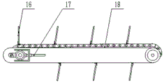
图3是本发明的辅助推送装置主视构造简图Figure 3 is a schematic diagram of the front view of the auxiliary push device of the present invention
图4是本发明辅助推送装置的俯视构造简图Figure 4 is a schematic top view of the structure of the auxiliary pushing device of the present invention
图5是本发明的洋葱切秧装置主视构造简图Figure 5 is a schematic diagram of the structure of the front view of the onion seedling cutting device of the present invention
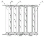
图6是本发明的洋葱切秧装置俯视构造简图FIG. 6 is a schematic plan view of the structure of the onion cutting device of the present invention.
图7是本发明输送上车装置的主视构造简图FIG. 7 is a schematic diagram of the front view of the conveying and loading device of the present invention.
图8是本发明输送上车装置的俯视构造简图FIG. 8 is a schematic top view of the structure of the conveying and loading device of the present invention.
图1中1.捡拾铲,2.悬挂架,3.机架,4.洋葱输送装置,5.辅助推送装置, 6.洋葱切秧装置,7.翻葱装置,8.输送上车装置。In Figure 1, 1. Picking up shovel, 2. Hanging frame, 3. Frame, 4. Onion conveying device, 5. Auxiliary pushing device, 6. Onion cutting device, 7. Onion turning device, 8. Conveying and loading device.
图2中9. 输送被动轴,10. 橡胶支撑辊1,11.栅条杆,12.输送主动轴,13. 主动橡胶轮1,14. 主动橡胶轮2,15.橡胶支撑轮2。In Figure 2, 9. Conveying passive shaft, 10.
图3中16.橡胶推送板,17.紧固螺杆,18.链节组。In Figure 3, 16. Rubber push plate, 17. Fastening screw, 18. Chain link group.
图4中19.被动链轮20.推送被动轴,21. 推送支撑梁2,22.推送支撑梁1,23. 推送主动轴,24. 主动链轮。In Figure 4, 19.
图5中25. 切秧链轮,26.切秧齿轮,27. 固定侧板。25. Cutting sprocket, 26. Cutting gear, 27. Fixed side plate in Figure 5.
图6中28. 切秧主动轴,29. 切秧螺旋杆,30. 切秧光杆,31.切秧被动轴。In Fig. 6, 28. Cutting active shaft, 29. Cutting screw, 30. Cutting smooth rod, 31. Cutting passive shaft.
图7中的32. 轴承座1,33. 翻葱主轴,34.翻葱侧板,35. 支板,36. 翻葱橡胶板,37. 轴承座2。In Figure 7, 32. Bearing seat 1, 33. Turning onion main shaft, 34. Turning onion side plate, 35. Support plate, 36. Turning onion rubber plate, 37. Bearing seat 2.
图8中的38. 输送架。38. Conveyor frame in Fig. 8.
图9中39.被动轮,40. 板带,41. 主动轮。In Figure 9, 39. passive wheel, 40. plate belt, 41. driving wheel.
具体实施方式Detailed ways
在图1所示的实施例中,首先将悬挂架(2)与拖拉机的液压悬挂系统对接,拖拉机行驶到作业现场时,驾驶员操作拖拉机液压分配器手柄,将机具放在地面,使安装在整体机架(3)前部的捡拾铲(1)接触地面,一档启动拖拉机,随拖拉机悬挂牵引着机具的前进,捡拾铲(1)将垄上的洋葱连带着一些土壤颗粒不断铲入机体内,进入洋葱输送装置(4),在洋葱输送装置运送洋葱的过程中,与洋葱一起裹入的土壤颗粒将在洋葱输送装置(4)的栅条杆(11)缝隙落入地面,辅助推送装置(5)转动将辅助洋葱输送装置(4)上运送的洋葱快速的推送到洋葱切秧装置(6),以防止洋葱在捡拾铲(1)和洋葱输送装置(6)交接位置发生壅堵现象,影响机具的正常行进工作,洋葱进入洋葱切秧装置(6)完成洋葱切秧的工作,安装在洋葱切秧装置(6)上方的翻葱装置(7)将遗漏没有切到残秧的洋葱进行翻动,将洋葱的残秧与洋葱切秧装置(6)中的切秧螺旋杆(29)和切秧光杆(30)接触完成切秧工作,同时将洋葱顺畅送达输送上车装置(8)位置,然后输送到农用运输车运送到目的地。In the embodiment shown in Fig. 1, the suspension frame (2) is first docked with the hydraulic suspension system of the tractor. When the tractor travels to the job site, the driver operates the handle of the hydraulic distributor of the tractor, puts the implement on the ground, and installs it on the ground. The pick-up shovel (1) at the front of the overall frame (3) touches the ground, starts the tractor in the first gear, and pulls the implement forward with the tractor suspension. The pick-up shovel (1) shovels the onions on the ridge together with some soil particles into the machine Inside, enter the onion conveying device (4), in the process of conveying the onion by the onion conveying device, the soil particles wrapped together with the onion will fall into the ground at the gap of the grid bar (11) of the onion conveying device (4), assisting the push The rotation of the device (5) quickly pushes the onions transported on the auxiliary onion conveying device (4) to the onion cutting device (6) to prevent the onion from being blocked at the handover position of the pick-up shovel (1) and the onion conveying device (6). The phenomenon affects the normal running of the machine. The onion enters the onion cutting device (6) to complete the work of cutting the onion. The onion is turned, and the residual onion is brought into contact with the cutting screw rod (29) and the smooth cutting rod (30) in the onion cutting device (6) to complete the cutting work, and at the same time, the onion is smoothly delivered to the conveying device (6). 8) Location, and then transported to the agricultural transport vehicle for delivery to the destination.
在图2所示的实施例中,橡胶支撑辊1(10)与橡胶支撑辊2(15)安装在输送被动轴(9)的两端,主动橡胶轮1(13)与主动橡胶轮2(14)安装在输送主动轴(12)的两端,工作时,输送主动轴(12)转动,输送主动轴(12)上安装的主动橡胶轮1(13)和主动橡胶轮2(14)通过与栅条杆(11)间隙相啮合而带动整个洋葱输送装置(4)开始向后上方运转,这套装置承接机器前方捡拾铲(1)捡拾上来的洋葱与土壤的混合物,在输送的过程中土壤颗粒在栅条杆(11)的缝隙落到地面,达到分离出土壤颗粒的作用。In the embodiment shown in FIG. 2, the rubber support roller 1 (10) and the rubber support roller 2 (15) are installed at both ends of the conveying driven shaft (9), the driving rubber wheel 1 (13) and the driving rubber wheel 2 ( 14) Installed on both ends of the conveying drive shaft (12), during operation, the conveying drive shaft (12) rotates, and the drive rubber wheel 1 (13) and the drive rubber wheel 2 (14) installed on the conveying drive shaft (12) pass through. It meshes with the gap of the grid bar (11) and drives the entire onion conveying device (4) to start running backward and upward. This device takes over the mixture of onion and soil picked up by the pick-up shovel (1) in front of the machine. During the conveying process The soil particles fall to the ground through the gaps of the grid bars (11) to achieve the effect of separating the soil particles.
在图3和图4所示的实施例中,两个主动链轮(24)分别安装在推送主动轴(23)左、右两端,两个被动链轮(19)分别安装在推送被动轴(20)左、右两端,两个链节组(18)分别啮合在左侧主、被动链轮和右侧主、被动链轮之间,并且在安装好的两链节组之间按一定距离安装橡胶推送板(16),工作时推送主动轴(23)转动,而推送主动轴(23)上两个主动链轮(24)通过与它们啮合的两套链节组带动整个辅助推送装置(5)开始运转,推送支撑梁1(22)与推送支撑梁2(21)支撑链条组(18),预防凹陷,橡胶推送板(16)向后运转将辅助洋葱输送装置(4)的输送工作,将其输送的洋葱顺利运送到下一个工作位置,这样在机器工作过程中,保证洋葱果实不会有壅堵甚至滑落返回地面的情况。In the embodiment shown in Figures 3 and 4, two driving sprockets (24) are respectively installed on the left and right ends of the pushing driving shaft (23), and two passive chain wheels (19) are respectively installed on the pushing driving shaft (20) On the left and right ends, the two chain link groups (18) are meshed between the left main and passive sprockets and the right main and passive sprockets, respectively, and press between the installed two chain link groups. The rubber push plate (16) is installed at a certain distance, the push drive shaft (23) rotates during operation, and the two drive sprockets (24) on the push drive shaft (23) drive the entire auxiliary push through the two sets of chain link groups that mesh with them. The device (5) starts to operate, the push support beam 1 (22) and the push support beam 2 (21) support the chain group (18) to prevent dents, and the rubber push plate (16) runs backwards to assist the onion conveying device (4). During the conveying work, the onions it conveyed are smoothly transported to the next working position, so that during the working process of the machine, it is guaranteed that the onion fruit will not be blocked or even slip back to the ground.
在图5和图6所示的实施例中,切秧主动轴(28)和切秧被动轴(31)安装在固定侧板(27)两端,按照交替排列规律,切秧螺旋杆(29)与切秧光杆(30)按一定距离交替安装5组,切秧链轮(25)安装在切秧主动轴(28)的两端,每根切秧螺旋杆(29)和切秧光杆(30)的两端安装有切秧齿轮(26),切秧齿轮(26)之间依次啮合,工作时,切秧链轮(25)转动驱动切秧主动轴(28)转动,安装在切秧主动轴(28)上的切秧齿轮(26)转动驱动与之相啮合的安装在切秧螺旋杆(29)的另一个切秧齿轮(26)转动,切秧螺旋杆(29)随之转动,切秧螺旋杆(29)上的切秧齿轮(26)驱动与之相啮合的切秧光杆(30)上的切秧齿轮(26)转动,切秧光杆(30)也随之转动,并且切秧螺旋杆(29)与切秧光杆(30)呈对向转动,将夹持的洋葱残秧夹持并切掉。In the embodiment shown in Figures 5 and 6, the cutting active shaft (28) and the passive cutting shaft (31) are installed at both ends of the fixed side plate (27), and the cutting screw rod (29) ) and the seedling cutting rod (30) are alternately installed in 5 groups at a certain distance, the seedling cutting sprocket (25) is installed on both ends of the seedling cutting driving shaft (28), each seedling cutting screw rod (29) and the seedling cutting rod ( 30) Both ends of the seedling cutting gear (26) are installed, and the seedling cutting gears (26) are meshed in sequence. During operation, the seedling cutting sprocket (25) rotates to drive the seedling cutting driving shaft (28) to rotate, and is installed on the cutting seedling. The seedling cutting gear (26) on the driving shaft (28) rotates to drive the other seedling cutting gear (26) installed on the seedling cutting screw rod (29) that meshes with it to rotate, and the seedling cutting screw rod (29) rotates accordingly. , the seedling cutting gear (26) on the seedling cutting screw rod (29) drives the seedling cutting gear (26) on the seedling cutting rod (30) meshed with it to rotate, and the seedling cutting rod (30) also rotates accordingly, and The seedling cutting screw rod (29) and the seedling cutting smooth rod (30) are rotated in opposite directions to clamp and cut off the retained onion residual seedlings.
图7所示的实施例中,轴承座1(32)和轴承座2(37)安装在翻葱主轴(33)的两端,轴承座1(32)和轴承座2(37)安装在机架(3)上,数根支板(35)焊接在两个翻葱侧板(34)的中间形成一个圆筒形结构,翻葱橡胶板(36)安装在支板(35)上,工作时,随着翻葱主轴(33)的转动,将洋葱切秧装置(6)上洋葱进行翻转,使没有被切到残秧的洋葱转动与洋葱切秧装置(6)接触完成切秧工作。In the embodiment shown in FIG. 7, the bearing seat 1 (32) and the bearing seat 2 (37) are installed on both ends of the turning shaft (33), and the bearing seat 1 (32) and the bearing seat 2 (37) are installed on the machine On the frame (3), several support plates (35) are welded to the middle of the two turning onion side plates (34) to form a cylindrical structure, and the turning onion rubber plate (36) is installed on the support plate (35) to work When the onion turning spindle (33) rotates, the onion on the onion seedling cutting device (6) is turned over, so that the onion that has not been cut into residual seedlings is rotated and contacted with the onion seedling cutting device (6) to complete the seedling cutting work.
在图8和图9所示的实施例中,输送上车装置(8)由输送架(38),主动轮(41),被动轮(39)和板带(40)组成,工作时可以调节输送角度以适应运输车的高度和位置。In the embodiment shown in Figures 8 and 9, the conveying and loading device (8) consists of a conveying frame (38), a driving wheel (41), a passive wheel (39) and a plate belt (40), which can be adjusted during operation Conveying angle to suit the height and position of the transporter.
Claims (4)
Priority Applications (1)
| Application Number | Priority Date | Filing Date | Title |
|---|---|---|---|
| CN202011004299.XA CN111937598A (en) | 2020-09-23 | 2020-09-23 | Onion picking and seedling cutting machine |
Applications Claiming Priority (1)
| Application Number | Priority Date | Filing Date | Title |
|---|---|---|---|
| CN202011004299.XA CN111937598A (en) | 2020-09-23 | 2020-09-23 | Onion picking and seedling cutting machine |
Publications (1)
| Publication Number | Publication Date |
|---|---|
| CN111937598A true CN111937598A (en) | 2020-11-17 |
Family
ID=73356366
Family Applications (1)
| Application Number | Title | Priority Date | Filing Date |
|---|---|---|---|
| CN202011004299.XA Pending CN111937598A (en) | 2020-09-23 | 2020-09-23 | Onion picking and seedling cutting machine |
Country Status (1)
| Country | Link |
|---|---|
| CN (1) | CN111937598A (en) |
Citations (4)
| Publication number | Priority date | Publication date | Assignee | Title |
|---|---|---|---|---|
| CN201393393Y (en) * | 2009-03-13 | 2010-02-03 | 任兰泽 | Self-propelled peanut combine harvester |
| CN207802774U (en) * | 2018-01-11 | 2018-09-04 | 酒泉华创戈壁农业科技有限公司 | One kind being convenient for clean onion harvester |
| CN211458027U (en) * | 2019-12-30 | 2020-09-11 | 山东农业大学 | Front-mounted garlic harvester |
| CN212812863U (en) * | 2020-09-23 | 2021-03-30 | 黑龙江省农业机械工程科学研究院齐齐哈尔农业机械化研究所 | Onion picking and cutting machine |
-
2020
- 2020-09-23 CN CN202011004299.XA patent/CN111937598A/en active Pending
Patent Citations (4)
| Publication number | Priority date | Publication date | Assignee | Title |
|---|---|---|---|---|
| CN201393393Y (en) * | 2009-03-13 | 2010-02-03 | 任兰泽 | Self-propelled peanut combine harvester |
| CN207802774U (en) * | 2018-01-11 | 2018-09-04 | 酒泉华创戈壁农业科技有限公司 | One kind being convenient for clean onion harvester |
| CN211458027U (en) * | 2019-12-30 | 2020-09-11 | 山东农业大学 | Front-mounted garlic harvester |
| CN212812863U (en) * | 2020-09-23 | 2021-03-30 | 黑龙江省农业机械工程科学研究院齐齐哈尔农业机械化研究所 | Onion picking and cutting machine |
Similar Documents
| Publication | Publication Date | Title |
|---|---|---|
| CN104396424B (en) | Self-propelled duplicate rows carrot combined harvester | |
| CN204408945U (en) | Self-propelled duplicate rows carrot combined harvester | |
| CN108633451B (en) | A new type of oblique roller ear-cracking fresh corn harvester | |
| CN115968629A (en) | A grading combine harvester for rhizome crops | |
| CN107836145B (en) | Machine for recovering residual film from field of large-root stubble crops such as sunflower and corn | |
| CN109997492A (en) | Double-row self-propelled green Chinese onion combine harvester and harvesting method | |
| CN114128476A (en) | A joint operation tool for potato digging and collecting | |
| CN102177783A (en) | Peanut combine harvester | |
| CN110121935A (en) | A kind of elastic claw rake topsoil incomplete film-recovering machine and application method | |
| CN111512764A (en) | Small self-propelled full-width seedling lifting harvester | |
| CN204653005U (en) | Double-deck shake chain potato harvester | |
| CN204317051U (en) | One elite stand fruit pick-up unit | |
| CN213029182U (en) | A small self-propelled full-width seedling harvester | |
| CN212812863U (en) | Onion picking and cutting machine | |
| CN110583203A (en) | Harvesting device of sole dioscorea | |
| CN204518466U (en) | A kind of seedling fruit separating mechanism of carrot reaping machine | |
| CN110537410B (en) | Two-section fritillary bulb harvester | |
| CN205431033U (en) | Potato digger transversal transport device | |
| CN206909139U (en) | A kind of root tuber class crop harvester | |
| CN219068916U (en) | tuber crop harvester | |
| CN109089511B (en) | Onion harvester with film removing and profiling conveying mechanisms | |
| CN216218856U (en) | A pick-up mechanism for peanut recycling | |
| CN210868757U (en) | Onion harvesting and film cleaning machine | |
| CN204408944U (en) | Toothed roller type carrot removes native device | |
| JP2004283139A (en) | Green onion harvester |
Legal Events
| Date | Code | Title | Description |
|---|---|---|---|
| PB01 | Publication | ||
| PB01 | Publication | ||
| SE01 | Entry into force of request for substantive examination | ||
| SE01 | Entry into force of request for substantive examination | ||
| WD01 | Invention patent application deemed withdrawn after publication | ||
| WD01 | Invention patent application deemed withdrawn after publication |
Application publication date: 20201117 |