CN210682392U - Tray carrying device adopting double manipulators to cooperatively operate - Google Patents
Tray carrying device adopting double manipulators to cooperatively operate Download PDFInfo
- Publication number
- CN210682392U CN210682392U CN201921378712.1U CN201921378712U CN210682392U CN 210682392 U CN210682392 U CN 210682392U CN 201921378712 U CN201921378712 U CN 201921378712U CN 210682392 U CN210682392 U CN 210682392U
- Authority
- CN
- China
- Prior art keywords
- clamping part
- transverse
- longitudinal
- manipulators
- rotating shaft
- Prior art date
- Legal status (The legal status is an assumption and is not a legal conclusion. Google has not performed a legal analysis and makes no representation as to the accuracy of the status listed.)
- Active
Links
Images
Landscapes
- Manipulator (AREA)
- Specific Conveyance Elements (AREA)
Abstract
The utility model discloses a tray carrying device adopting two manipulators to cooperatively work, which comprises at least two groups of carrying manipulators, wherein each group of carrying manipulators comprises a clamping part, a longitudinal moving component for controlling the lifting of the clamping part and a transverse moving component for controlling the horizontal movement of the clamping part; the clamping part is arranged on a rotating shaft, and the rotating shaft is controlled by a driving motor to drive the clamping part to horizontally rotate 360 degrees; the clamping part is provided with two claw ends which can move oppositely or oppositely. The utility model discloses set up at least two sets of transport manipulators, the round trip movement of tray is accomplished in the branch worker of transport manipulator, and whole process goes on in step, each other does not influence, and the effectual shut down latency with processing equipment shortens within 3s, makes the equipment of processing region produce always, has greatly improved production efficiency.
Description
Technical Field
The utility model relates to a material conveying system, in particular to adopt tray handling device of two manipulators collaborative operation.
Background
And along with automatic application, automatic transport handling system has appeared, including roller transfer chain, transport truss manipulator, positioning mechanism, stop gear and frock bearing mechanism, transport truss manipulator erects directly over the roller transfer chain, and positioning mechanism is located the rear of transport truss manipulator and installs in one side of roller transfer chain, and stop gear is located positioning mechanism's rear and installs on the roller transfer chain, and frock bearing mechanism is located the end of roller transfer chain is erect directly over the roller transfer chain, and the cooperation is equipped with frock climbing mechanism directly under the frock bearing mechanism, generally is used for replacing simple manually operation.
When the tray is used, a product to be processed is placed on the tray, the truss mechanical arm needs to be carried to move the tray from the conveying line to the processing equipment for processing, after the processing is completed, the truss mechanical arm needs to be carried to move the tray back to the conveying line from the processing equipment, and after the tray is moved back to the conveying line, the truss mechanical arm is carried to move a new tray to the processing equipment, and in the process, the processing equipment is always in an idle state, so that the overall working efficiency is greatly reduced.
Disclosure of Invention
The utility model aims at providing an adopt tray handling device of two manipulators collaborative operation can solve the tray and make a round trip the handling process time too long problem from the transfer chain to the processing equipment.
Therefore, the technical scheme of the utility model is that: the utility model provides an adopt tray handling device of two manipulators collaborative operation which characterized in that: the device comprises at least two groups of carrying manipulators, wherein each group of carrying manipulators comprises a clamping part, a longitudinal moving assembly for controlling the clamping part to ascend and descend and a transverse moving assembly for controlling the clamping part to horizontally move; the clamping part is arranged on a rotating shaft, and the rotating shaft is controlled by a driving motor to drive the clamping part to horizontally rotate 360 degrees; the clamping part is provided with two claw ends which can move oppositely or oppositely.
Furthermore, the clamping part is installed on a rotating support through a rotating shaft, one end of the rotating shaft is used for fixing the clamping part, and the other end of the rotating shaft is connected with a rotary driving motor through a synchronous pulley set.
Furthermore, the longitudinal moving assembly comprises a longitudinal cylinder, a longitudinal sliding rail and a longitudinal sliding block, the rotating support is fixedly mounted on the longitudinal sliding block, the longitudinal sliding block is movably matched with the longitudinal sliding rail, the longitudinal sliding block is connected with a cylinder rod of the longitudinal cylinder, and the longitudinal cylinder drives the longitudinal sliding block to move along the longitudinal sliding rail.
Further, the lateral shifting subassembly includes transverse motor, lead screw, transverse guide and horizontal movable block, and the transverse motor drives the rotation of horizontal lead screw, and horizontal movable block is installed on horizontal lead screw, and both normal running fit, and on transverse guide was arranged in to horizontal movable block, both sliding fit, the longitudinal movement subassembly was installed on horizontal movable block.
The single mechanical arm of the utility model drives the screw rod to rotate through the transverse motor, thereby controlling the transverse movement of the clamping part; the vertical position of the clamping part is directly adjusted by a longitudinal moving cylinder. The guide rails are respectively arranged in the longitudinal direction and the transverse direction, so that the clamping part can move stably and reliably. Meanwhile, the clamping part is controlled by a driving motor and a synchronous belt wheel to realize 360-degree rotation position adjustment; the synchronous belt wheel can be also provided with a tensioning mechanism to ensure the transmission effectiveness of the synchronous belt. The two claw ends of the clamping part can move oppositely or oppositely, the width of the clamping part can be automatically adjusted to adapt to trays with different specifications, and the direction of the tray can be rotated at any angle according to the requirement of processing equipment on the posture of a product; the adjustable degree range of the clamping part is 185 mm-500 mm, and the rotating angle precision of the clamping part is +/-0.1 degrees.
The utility model discloses set up at least two sets of transport manipulators, wherein a set of transport manipulator can press from both sides the tray and place the processing region, wait for preceding tray and accomplish processing, and the second group transport manipulator then presss from both sides the tray after accomplishing and takes back on conveying mechanism, and whole process goes on in step, each other does not influence, and effectual shut down latency with the processing equipment shortens within 3s, makes the regional equipment of processing always produce, has greatly improved production efficiency.
Drawings
The following detailed description is made with reference to the accompanying drawings and embodiments of the present invention
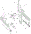
Fig. 1 is a schematic structural view of the present invention;
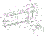
fig. 2 is a schematic structural view of a single handling robot.
Labeled as: the device comprises a first conveying manipulator 61, a second conveying manipulator 62, a clamping part 63, a rotating bracket 64, a synchronous pulley set 65, a rotating driving motor 66, a longitudinal cylinder 67, a longitudinal slide rail 68, a transverse motor 69, a transverse screw rod 70, a transverse drag chain 71, a longitudinal drag chain 72, a transverse guide rail 73 and a transverse movable block 74.
Detailed Description
See the drawings. This embodiment includes two sets of transport manipulators, and first transport manipulator 61 can press from both sides the tray and place the processing region, waits for preceding tray to accomplish processing, and second transport manipulator 62 then will accomplish the tray after press from both sides get back conveying mechanism on, whole process goes on in step, each other does not influence.
Each group of carrying manipulators comprises a clamping part 63 which is provided with two claw ends which can move oppositely or oppositely; the clamping part 63 is mounted on a rotating bracket 64 through a rotating shaft, one end of the rotating shaft is fixed with the clamping part, and the other end of the rotating shaft is connected with a rotating driving motor 66 through a synchronous pulley set 65 and is controlled by the driving motor to drive the clamping part 63 to horizontally rotate 360 degrees; and further comprises a longitudinal moving component for controlling the lifting of the clamping part 63 and a transverse moving component for controlling the horizontal movement of the clamping part 63.
The longitudinal moving assembly comprises a longitudinal cylinder 67, a longitudinal sliding rail 68 and a longitudinal sliding block, the rotating support 64 is fixedly mounted on the longitudinal sliding block, the longitudinal sliding block is movably matched with the longitudinal sliding rail, the longitudinal sliding block is connected with a cylinder rod of the longitudinal cylinder 67, and the longitudinal cylinder 67 drives the longitudinal sliding block to move along the longitudinal sliding rail, so that the clamping part 63 can move in the vertical direction.
The transverse moving assembly comprises a transverse motor 69, a transverse screw rod 70, a transverse guide rail 73 and a transverse moving block 74, wherein the transverse motor 69 drives the transverse screw rod 70 to rotate, the transverse moving block 74 is installed on the transverse screw rod 70 and is in rotating fit with the transverse screw rod 70, the transverse moving block 74 is arranged on the transverse guide rail 73 and is in sliding fit with the transverse screw rod 73, and therefore the transverse screw rod 70 rotates, and the transverse moving block 74 moves horizontally along the transverse guide rail 73. The longitudinal movement assembly is mounted on the lateral movable block 74 so as to effect the back and forth movement of the gripping portion 63 in the horizontal direction. The carrying robot is further provided with a transverse drag chain 71 and a longitudinal drag chain 72, cables are bound, and the clamping parts can conveniently move in the horizontal direction and the vertical direction.
Claims (4)
1. The utility model provides an adopt tray handling device of two manipulators collaborative operation which characterized in that: the device comprises at least two groups of carrying manipulators, wherein each group of carrying manipulators comprises a clamping part, a longitudinal moving assembly for controlling the clamping part to ascend and descend and a transverse moving assembly for controlling the clamping part to horizontally move; the clamping part is arranged on a rotating shaft, and the rotating shaft is controlled by a driving motor to drive the clamping part to horizontally rotate 360 degrees; the clamping part is provided with two claw ends which can move oppositely or oppositely.
2. The pallet conveying apparatus using the two robots cooperatively operated according to claim 1, wherein: the clamping part is installed on a rotating support through a rotating shaft, one end of the rotating shaft is used for fixing the clamping part, and the other end of the rotating shaft is connected with a rotary driving motor through a synchronous pulley set.
3. The pallet conveying apparatus using the two robots cooperatively operated according to claim 2, wherein: the longitudinal moving assembly comprises a longitudinal cylinder, a longitudinal sliding rail and a longitudinal sliding block, the rotating support is fixedly mounted on the longitudinal sliding block, the longitudinal sliding block is movably matched with the longitudinal sliding rail, the longitudinal sliding block is connected with a cylinder rod of the longitudinal cylinder, and the longitudinal cylinder drives the longitudinal sliding block to move along the longitudinal sliding rail.
4. The pallet conveying apparatus using the two robots cooperatively operated according to claim 1, wherein: the transverse moving assembly comprises a transverse motor, a screw rod, a transverse guide rail and a transverse moving block, the transverse motor drives the transverse screw rod to rotate, the transverse moving block is installed on the transverse screw rod and is in rotating fit with the transverse screw rod, the transverse moving block is arranged on the transverse guide rail and is in sliding fit with the transverse moving block, and the longitudinal moving assembly is installed on the transverse moving block.
Priority Applications (1)
| Application Number | Priority Date | Filing Date | Title |
|---|---|---|---|
| CN201921378712.1U CN210682392U (en) | 2019-08-23 | 2019-08-23 | Tray carrying device adopting double manipulators to cooperatively operate |
Applications Claiming Priority (1)
| Application Number | Priority Date | Filing Date | Title |
|---|---|---|---|
| CN201921378712.1U CN210682392U (en) | 2019-08-23 | 2019-08-23 | Tray carrying device adopting double manipulators to cooperatively operate |
Publications (1)
| Publication Number | Publication Date |
|---|---|
| CN210682392U true CN210682392U (en) | 2020-06-05 |
Family
ID=70889216
Family Applications (1)
| Application Number | Title | Priority Date | Filing Date |
|---|---|---|---|
| CN201921378712.1U Active CN210682392U (en) | 2019-08-23 | 2019-08-23 | Tray carrying device adopting double manipulators to cooperatively operate |
Country Status (1)
| Country | Link |
|---|---|
| CN (1) | CN210682392U (en) |
Cited By (3)
| Publication number | Priority date | Publication date | Assignee | Title |
|---|---|---|---|---|
| CN110540027A (en) * | 2019-08-23 | 2019-12-06 | 杭州优智物联科技有限公司 | Intelligent conveying system and method |
| CN111891743A (en) * | 2020-08-05 | 2020-11-06 | 陈卫华 | Transition transfer carrying device for milk tea machine |
| CN113501291A (en) * | 2021-07-21 | 2021-10-15 | 珠海格力智能装备有限公司 | Move and carry mechanism and have its production line |
-
2019
- 2019-08-23 CN CN201921378712.1U patent/CN210682392U/en active Active
Cited By (4)
| Publication number | Priority date | Publication date | Assignee | Title |
|---|---|---|---|---|
| CN110540027A (en) * | 2019-08-23 | 2019-12-06 | 杭州优智物联科技有限公司 | Intelligent conveying system and method |
| CN110540027B (en) * | 2019-08-23 | 2024-06-11 | 浙江优智物联科技有限公司 | Intelligent conveying system and method |
| CN111891743A (en) * | 2020-08-05 | 2020-11-06 | 陈卫华 | Transition transfer carrying device for milk tea machine |
| CN113501291A (en) * | 2021-07-21 | 2021-10-15 | 珠海格力智能装备有限公司 | Move and carry mechanism and have its production line |
Similar Documents
| Publication | Publication Date | Title |
|---|---|---|
| CN210682392U (en) | Tray carrying device adopting double manipulators to cooperatively operate | |
| CN103056874B (en) | Mechanical arm for high-speed carrying | |
| JP6174261B2 (en) | Conveyor for work | |
| JP4692163B2 (en) | Work positioning support device and work positioning support method | |
| CN204819563U (en) | Multidirectional arm | |
| KR101860195B1 (en) | the transfer robot and the transfer system therewith | |
| CN107685218B (en) | Welding processing line | |
| CN111653510B (en) | Graphite boat conveying equipment and conveying method | |
| CN104117734B (en) | Chamfer processing device | |
| CN110039280B (en) | Automatic assembling device and method for tensioner shaft pin | |
| CN109279341A (en) | A kind of supporting parts feeding, discharge equipment applying to ceramic rod production | |
| CN206886089U (en) | A kind of bin system | |
| CN210084414U (en) | Multi-axis moving and automatic feeding manipulator | |
| CN107472855A (en) | A kind of bin system | |
| CN216505182U (en) | Mechanical grabbing device for industrial robot | |
| CN114030849B (en) | Workpiece feeding device of steel pipe inner and outer wall coating production line | |
| CN115771734A (en) | Truss type stacking robot | |
| CN107159761A (en) | Horizontal bender | |
| CN211077623U (en) | Clamping and moving device | |
| CN209720930U (en) | Battery charging and discharging mechanism | |
| KR100837158B1 (en) | A robot for material transfer and forge upsetting method thereof | |
| CN108568692B (en) | Machine-position loading and unloading equipment | |
| CN221562152U (en) | Ten-axis servo manipulator | |
| CN220560842U (en) | Automatic assembly equipment for plastic package assembly | |
| CN202542372U (en) | Modular automatic production device |
Legal Events
| Date | Code | Title | Description |
|---|---|---|---|
| GR01 | Patent grant | ||
| GR01 | Patent grant |