CN216505182U - Mechanical grabbing device for industrial robot - Google Patents
Mechanical grabbing device for industrial robot Download PDFInfo
- Publication number
- CN216505182U CN216505182U CN202123161825.6U CN202123161825U CN216505182U CN 216505182 U CN216505182 U CN 216505182U CN 202123161825 U CN202123161825 U CN 202123161825U CN 216505182 U CN216505182 U CN 216505182U
- Authority
- CN
- China
- Prior art keywords
- top plate
- industrial robot
- driven roller
- conveying belt
- driving roller
- Prior art date
- Legal status (The legal status is an assumption and is not a legal conclusion. Google has not performed a legal analysis and makes no representation as to the accuracy of the status listed.)
- Active
Links
Images


Abstract
The utility model discloses a mechanical grabbing device for an industrial robot, which comprises a top plate and a plurality of fixing frames, wherein the fixing frames are arranged at the lower end of the top plate, a driving roller and a driven roller are respectively arranged in the fixing frames, conveying belts are respectively wound outside the driving roller and the driven roller, a plurality of connecting rods are arranged on the driven roller at one side, a baffle is uniformly fixed on the plurality of connecting rods, a panel is respectively arranged in the conveying belts, a plurality of sliding grooves are axially arranged on the bottom surface of the top plate, sliding blocks are respectively arranged at positions, opposite to the sliding grooves, of the fixing frame at the left side, the sliding blocks are respectively arranged in the sliding grooves in a sliding manner, and a driving mechanism for driving the sliding blocks to move is arranged on the top plate. The utility model has simple structure, can clamp the object inwards by the fixing frame through the driving mechanism, can convey the object upwards by the rotating conveying belt, increases the contact area between the object and the conveying belt, can synchronously drive the baffle plate in the conveying process, enables the baffle plate to automatically rotate to the position below the object, can connect the falling object, and increases the grabbing safety.
Description
Technical Field
The utility model relates to the technical field of mechanical grabbing, in particular to a mechanical grabbing device for an industrial robot.
Background
With the continuous development of science and technology, the number of robots used in industry is also increasing, and the application range is wider and wider, and an industrial robot is a multi-joint manipulator facing the industrial field or a multi-degree-of-freedom machine device, can automatically execute work, and is a machine which realizes various functions by means of self power and control capability. The industrial robot is usually provided with a mechanical gripping device for matching with the normal use of each functional module, the force of the general gripping device is not easy to control, when some objects with insufficient hardness are gripped, such as until objects such as a box body and a plastic box body, the object which is gripped can be damaged by too large force, and the object which is gripped by the small force can also fall off.
Disclosure of Invention
The technical problem to be solved by the present invention is to provide a mechanical grabbing device for an industrial robot, so as to solve the problems proposed in the background art.
The utility model is realized by the following technical scheme: the utility model provides an industrial robot uses mechanical grabbing device, including roof and a plurality of mount, the mount sets up in the roof lower extreme, inside drive roll and the driven voller of all being equipped with of mount, the outside of drive roll and driven voller all coils and is equipped with the conveyer belt, install many connecting rods on the driven voller of one side, many connecting rods are fixed with the baffle in unison, the baffle is "L" type structure setting, the inside of conveyer belt all is equipped with the panel, a side of panel all touches with the inner circle face of conveyer belt, the both sides of panel are all installed on the mount, the axial is equipped with many spouts on the bottom surface of roof, the slider is all installed to spout department just to left mount, the equal slidable mounting of slider is in the spout, the mount on right side is installed on the bottom surface of roof, install the actuating mechanism who drives the slider removal on the roof.
As the preferred technical scheme, actuating mechanism includes gear motor, screw rod and first bearing, is equipped with the screw hole that runs through the slider on the slider in the middle of, and middle spout one end is equipped with and communicates the shaft hole with the external world, and first bearing is embedded to be installed on the other end of spout, and screw rod threaded connection is in the screw hole, and screw rod one end is installed in the inner circle of first bearing, and the other end passes the shaft hole to pivot fixed connection through shaft coupling and gear motor, the cross-section of slider and spout all is the setting of dovetail structure.
As the preferred technical scheme, the fixing frames are all arranged in a U-shaped structure, second bearings are installed at the positions, opposite to rotating shafts of the driving roller and the driven roller, of the fixing frames in an embedded mode, the rotating shafts of the driving roller and the driven roller are installed in inner rings of the second bearings, servo motors are installed on one side face of each fixing frame, and the rotating shafts of the servo motors are welded and fixed with the rotating shaft at one end of the driving roller.
As preferred technical scheme, the conveyer belt is made by rubber materials, and inside equal cavity sets up, and the conveyer belt is inside all to be annotated with gas.
As preferred technical scheme, install a plurality of connecting seats of being connected with the arm on the top surface of roof.
As the preferred technical scheme, the driving roller is positioned on both sides of the conveying belt and is provided with a limiting ring.
The utility model has the beneficial effects that: the utility model has simple structure, can lead the fixed frame to clamp the object inwards through the driving mechanism, can lead the object to extrude the conveying belt after the object is contacted with the conveying belt, leads the contact part of the conveying belt and the object to form a concave groove, increases the positioning effect of the object, can lead the object to be conveyed upwards through the rotating conveying belt, increases the contact area of the object and the conveying belt, can synchronously drive the baffle plate in the conveying process, leads the baffle plate to be automatically rotated to the lower part of the object, can lead the fallen object to be connected, and increases the grabbing safety.
Drawings
In order to more clearly illustrate the embodiments of the present invention or the technical solutions in the prior art, the drawings used in the description of the embodiments or the prior art will be briefly described below, it is obvious that the drawings in the following description are only some embodiments of the present invention, and for those skilled in the art, other drawings can be obtained according to the drawings without creative efforts.
FIG. 1 is a schematic view of the overall structure of the present invention;
FIG. 2 is a cross-sectional view of the present invention;
fig. 3 is a schematic view of the installation structure of the panel of the present invention.
Detailed Description
Reference will now be made in detail to embodiments of the present invention, examples of which are illustrated in the accompanying drawings, wherein like or similar reference numerals refer to the same or similar elements or elements having the same or similar function throughout. The embodiments described below with reference to the accompanying drawings are illustrative only for the purpose of explaining the present invention, and are not to be construed as limiting the present invention.
In the description of the present invention, it is to be understood that the terms "center", "upper", "lower", "front", "rear", "left", "right", "vertical", "horizontal", "top", "bottom", "inner", "outer", etc., indicate orientations or positional relationships based on those shown in the drawings, and are only for convenience of description and simplicity of description, and do not indicate or imply that the devices or elements referred to must have a particular orientation, be constructed and operated in a particular orientation, and thus, are not to be construed as limiting the present invention.
In the description of the present invention, it should be noted that unless otherwise explicitly stated or limited, the terms "mounted," "connected," and "disposed" are to be construed broadly and can, for example, be fixedly connected, disposed, detachably connected, disposed, or integrally connected and disposed. The specific meanings of the above terms in the present invention can be understood in specific cases to those skilled in the art.
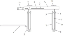
As shown in fig. 1, 2 and 3, the mechanical gripping device for an industrial robot according to the present invention is characterized in that: the device comprises a top plate 1 and a plurality of fixing frames 2, wherein the fixing frames 2 are arranged at the lower end of the top plate 1, a driving roller 3 and a driven roller 4 are respectively arranged in the fixing frames 2, a conveying belt 15 is respectively wound outside the driving roller 3 and the driven roller 4, a plurality of connecting rods 5 are arranged on the driven roller 4 at one side, a baffle 6 is uniformly fixed on the plurality of connecting rods 5, the baffle 6 is arranged in an L-shaped structure, a panel 7 is respectively arranged in the conveying belt 15, one side surface of the panel 7 is contacted with the inner circle surface of the conveying belt 15, two sides of the panel 7 are respectively arranged on the fixing frames 2, a plurality of sliding grooves 9 are axially arranged on the bottom surface of the top plate 1, a slide block 12 is respectively arranged at the position of the left fixing frame 2 opposite to the sliding grooves, the slide block 12 is respectively arranged in the sliding grooves, the right fixing frame 2 is arranged on the bottom surface of the top plate 1, a driving mechanism for driving the slide block to move is arranged on the top plate 1, wherein the middle of the conveying belt has a supporting effect through the baffle, the bending deformation in the middle of the conveying belt is avoided.
In this embodiment, actuating mechanism includes gear motor 13, screw rod 11 and first bearing, be equipped with the screw hole 17 that runs through the slider on the slider 12 in the middle of, 9 one end of middle spout is equipped with and communicates the shaft hole with the external world, the embedded installation of first bearing is on the other end of spout, 11 threaded connection of screw rod is in screw hole 17, 11 one end of screw rod is installed in the inner circle of first bearing, the other end passes the shaft hole, and pivot fixed connection through shaft coupling and gear motor 13, the cross-section of slider 12 and spout 9 all is the setting of dovetail structure.
In this embodiment, the fixing frame 2 is in a U-shaped structure, the second bearings 16 are installed in the positions of the fixing frame 2 opposite to the rotating shafts of the driving roller and the driven roller in an embedded manner, the rotating shafts of the driving roller 3 and the driven roller 4 are installed in the inner rings of the second bearings, the servo motors 18 are installed on one side faces of the fixing frame 2, and the rotating shafts of the servo motors 18 are welded and fixed with the rotating shaft of one end of the driving roller 3.
In this embodiment, 15 are made by rubber materials for the conveyer belt, and inside equal cavity sets up, and conveyer belt inside is all annotated has gas, has increased the flexibility of conveyer belt, also makes the object can extrude the conveyer belt, makes the corresponding region of conveyer belt sunken, increases the location effect.
In this embodiment, a plurality of connecting seats 14 connected to the robot arm are installed on the top surface of the top plate 1.
In this embodiment, the driving roller 3 is located the both sides of conveyer belt and all installs spacing ring 8, has avoided the conveyer belt to move toward both sides.
When in use, the device is arranged on the mechanical arm, the device is moved by the mechanical arm until the fixed frame is moved to two sides of an object, at the moment, the speed reducing motor is started, the screw rod is driven by the starting of the speed reducing motor, the slide block is driven by the rotation of the screw rod, the left fixed frame and the left conveying belt are driven by the slide block, the object can extrude the conveying belt after the object is contacted with the conveying belt, a concave groove is formed at the contact part of the conveying belt and the object, the positioning effect on the object is increased, the servo motor is started, the driving roller is driven by the starting of the servo motor, the conveying belt and the driven roller are driven by the rotation of the driving roller, the object can be conveyed upwards by the rotating conveying belt, the contact area between the object and the conveying belt is increased, the driven roller can synchronously drive the connecting rod and the baffle plate, the baffle plate rotates anticlockwise until the baffle plate is automatically rotated to the lower part, the dropped object can be contacted, the safety of grabbing is increased.
The above description is only an embodiment of the present invention, but the scope of the present invention is not limited thereto, and any changes or substitutions that are not thought of through the inventive work should be included in the scope of the present invention. Therefore, the protection scope of the present invention shall be subject to the protection scope defined by the claims.
Claims (6)
1. The utility model provides an industrial robot is with mechanical grabbing device which characterized in that: the device comprises a top plate (1) and a plurality of fixing frames (2), wherein the fixing frames (2) are arranged at the lower end of the top plate (1), a driving roller (3) and a driven roller (4) are arranged inside the fixing frames (2), a conveying belt (15) is arranged outside the driving roller (3) and the driven roller (4) in a coiling manner, a plurality of connecting rods (5) are arranged on the driven roller (4) at one side, a baffle (6) is uniformly fixed on the plurality of connecting rods (5), the baffle (6) is arranged in an L-shaped structure, a panel (7) is arranged inside the conveying belt (15), one side surface of the panel (7) is contacted with the inner circle surface of the conveying belt (15), two sides of the panel (7) are arranged on the fixing frames (2), a plurality of sliding grooves (9) are axially arranged on the bottom surface of the top plate (1), a sliding block (12) is arranged right at the sliding groove of the left fixing frame (2), and the sliding block (12) is arranged in the sliding manner, the fixed frame (2) on the right side is arranged on the bottom surface of the top plate (1), and a driving mechanism for driving the sliding block to move is arranged on the top plate (1).
2. The mechanical grasping apparatus for an industrial robot according to claim 1, characterized in that: actuating mechanism includes gear motor (13), screw rod (11) and first bearing, be equipped with screw hole (17) that run through the slider on middle slider (12), middle spout (9) one end is equipped with and communicates the shaft hole with the external world, the embedded installation of first bearing is on the other end of spout, screw rod (11) threaded connection is in screw hole (17), screw rod (11) one end is installed in the inner circle of first bearing, the other end passes the shaft hole, and pivot fixed connection through shaft coupling and gear motor (13), the cross-section of slider (12) and spout (9) all is the setting of dovetail structure.
3. The mechanical grasping apparatus for an industrial robot according to claim 1, characterized in that: the fixing frame (2) is of a U-shaped structure, the second bearing (16) is installed in the position, corresponding to the rotating shaft of the driving roller and the rotating shaft of the driven roller, of the fixing frame (2) in an embedded mode, the rotating shafts of the driving roller (3) and the rotating shaft of the driven roller (4) are installed in the inner ring of the second bearing, the servo motor (18) is installed on one side face of the fixing frame (2), and the rotating shaft of the servo motor (18) is welded and fixed with the rotating shaft of one end of the driving roller (3).
4. The mechanical grasping apparatus for an industrial robot according to claim 1, characterized in that: conveyer belt (15) are made by rubber materials, and inside all cavity sets up, and conveyer belt inside all is annotated has gas.
5. The mechanical grasping apparatus for an industrial robot according to claim 1, characterized in that: a plurality of connecting seats (14) connected with the mechanical arm are arranged on the top surface of the top plate (1).
6. The mechanical grasping apparatus for an industrial robot according to claim 1, characterized in that: limiting rings (8) are arranged on two sides of the conveying belt of the driving roller (3).
Priority Applications (1)
| Application Number | Priority Date | Filing Date | Title |
|---|---|---|---|
| CN202123161825.6U CN216505182U (en) | 2021-12-16 | 2021-12-16 | Mechanical grabbing device for industrial robot |
Applications Claiming Priority (1)
| Application Number | Priority Date | Filing Date | Title |
|---|---|---|---|
| CN202123161825.6U CN216505182U (en) | 2021-12-16 | 2021-12-16 | Mechanical grabbing device for industrial robot |
Publications (1)
| Publication Number | Publication Date |
|---|---|
| CN216505182U true CN216505182U (en) | 2022-05-13 |
Family
ID=81499326
Family Applications (1)
| Application Number | Title | Priority Date | Filing Date |
|---|---|---|---|
| CN202123161825.6U Active CN216505182U (en) | 2021-12-16 | 2021-12-16 | Mechanical grabbing device for industrial robot |
Country Status (1)
| Country | Link |
|---|---|
| CN (1) | CN216505182U (en) |
Cited By (1)
| Publication number | Priority date | Publication date | Assignee | Title |
|---|---|---|---|---|
| CN115724218B (en) * | 2022-11-03 | 2024-04-23 | 合肥哈工龙延智能装备有限公司 | Four-axis palletizing robot for intelligent packaging assembly line |
-
2021
- 2021-12-16 CN CN202123161825.6U patent/CN216505182U/en active Active
Cited By (1)
| Publication number | Priority date | Publication date | Assignee | Title |
|---|---|---|---|---|
| CN115724218B (en) * | 2022-11-03 | 2024-04-23 | 合肥哈工龙延智能装备有限公司 | Four-axis palletizing robot for intelligent packaging assembly line |
Similar Documents
| Publication | Publication Date | Title |
|---|---|---|
| CN113001311A (en) | Aluminum casting robot polishing workstation | |
| CN210081283U (en) | Automatic grabbing mechanical arm | |
| CN210389191U (en) | Lifting mechanism for grabbing | |
| JP2010094695A (en) | Workpiece conveying apparatus | |
| CN216154882U (en) | Plate planting machine with automatic plate turning function | |
| CN102528793A (en) | End effector overturnable mechanism for carrying plate-shaped workpiece | |
| JPH0531685A (en) | Multiarm turning type articulated robot | |
| CN210682392U (en) | Tray carrying device adopting double manipulators to cooperatively operate | |
| CN210996518U (en) | Flexible automatic production line for sucker rod coupling | |
| CN111136444B (en) | Full-automatic rotor shaft core pressing-in production line and working method thereof | |
| CN216505182U (en) | Mechanical grabbing device for industrial robot | |
| CN105691720A (en) | Feeding device | |
| CN211916825U (en) | Cross arm joint manipulator | |
| CN209815087U (en) | Corner machine with lifting function | |
| CN210527875U (en) | Robot end effector for stacking refractory bricks | |
| CN111960095A (en) | Aluminum ingot transfer device | |
| JP5098562B2 (en) | Workpiece transfer robot and transfer method | |
| CN110026975A (en) | A kind of universal manipulator of industrial automation assembly line | |
| CN217143941U (en) | Three-axis manipulator | |
| CN210418177U (en) | Feed mechanism is used in processing of optics electronic equipment part | |
| CN208613581U (en) | A kind of automatic charging machine of press bed | |
| CN112140097A (en) | Workpiece feeding manipulator | |
| CN214603517U (en) | Aluminum casting robot polishing workstation | |
| CN214494465U (en) | Jig backflow type assembly line | |
| CN218538409U (en) | Intelligent manipulator with automatic identification function |
Legal Events
| Date | Code | Title | Description |
|---|---|---|---|
| GR01 | Patent grant | ||
| GR01 | Patent grant |