CN211916825U - Cross arm joint manipulator - Google Patents
Cross arm joint manipulator Download PDFInfo
- Publication number
- CN211916825U CN211916825U CN201922118492.5U CN201922118492U CN211916825U CN 211916825 U CN211916825 U CN 211916825U CN 201922118492 U CN201922118492 U CN 201922118492U CN 211916825 U CN211916825 U CN 211916825U
- Authority
- CN
- China
- Prior art keywords
- motor
- guide rail
- elevating system
- base
- support frame
- Prior art date
- Legal status (The legal status is an assumption and is not a legal conclusion. Google has not performed a legal analysis and makes no representation as to the accuracy of the status listed.)
- Active
Links
Images
Landscapes
- Manipulator (AREA)
Abstract
The utility model discloses a xarm joint manipulator, include base, elevating system, horizontal migration mechanism, angle adjustment mechanism and snatch the mechanism, the base upper end is equipped with elevating system, and the elevating system upper end is equipped with horizontal migration mechanism, is equipped with angle adjustment mechanism on the horizontal migration mechanism, and angle adjustment mechanism one side is connected with snatchs the mechanism, snatchs the mechanism lower extreme and is connected with mechanical clamping jaw. The utility model discloses a direction and horizontal direction's removal about elevating system, horizontal migration mechanism realize through angle adjustment mechanism that mechanical clamping jaw is 270 degrees rotations in the horizontal direction, compares the not hard up of avoiding the belt pulley with the transmission of belt pulley through lead screw driven mode simultaneously, produces the influence to the precision of position.
Description
Technical Field
The utility model relates to an automation equipment technical field, concretely relates to multi-angle displacement manipulator.
Background
The manipulator is an automatic operating device for grabbing and carrying articles or operating tools according to a fixed program, can replace heavy labor of people to realize mechanization and automation of production, can operate in a harmful environment to protect personal safety, and is widely applied to stations of mechanical manufacturing, metallurgy, electronics, light industry, atomic energy and the like. At present, a plurality of mechanical arms are matched in a production workshop, so that workpieces with different angles and heights can be transferred or transferred, the production cost is increased, and the workpieces are easily damaged by clamping of a plurality of clamping jaws. At present, the transmission between the multi-axis manipulators adopts a speed reducer and a belt pulley to achieve the multi-dimensional action of the manipulators, but the belt pulley is easy to damage, so that the precision of the motion position is influenced.
Therefore, to the above problem, the utility model provides a new technical scheme.
SUMMERY OF THE UTILITY MODEL
The utility model aims at providing a rational in infrastructure adopts the lead screw conveying, realizes the manipulator of multidimension degree, multi-angle action.
The utility model discloses a realize through following technical scheme:
the utility model provides a xarm joint manipulator, includes base, elevating system, horizontal migration mechanism, angle adjustment mechanism and snatchs the mechanism, the base upper end is equipped with elevating system, the elevating system upper end is equipped with horizontal migration mechanism, the last angle adjustment mechanism that is equipped with of horizontal migration mechanism, angle adjustment mechanism one side is connected with snatchs the mechanism, it is connected with mechanical clamping jaw to snatch the mechanism lower extreme.
Further, elevating system includes support frame, first guide rail, first motor, first slider and first lead screw, support frame fixed mounting is on the base, fixed mounting has first guide rail on the support frame terminal surface, be equipped with first slider on the first guide rail, the support frame bottom is equipped with first motor, first motor is connected with the first lead screw that is located the support frame, first slider is connected to first lead screw, horizontal migration mechanism is installed to first slider upper end.
Further, the horizontal movement mechanism comprises a bottom plate, a second guide rail, a second motor, a second sliding block and a second lead screw, the bottom plate is fixedly installed on the first sliding block, the second guide rail is fixedly installed at the upper end of the bottom plate, the second motor is arranged on one side of the second guide rail, the second motor is connected with the second lead screw installed in the second guide rail, the second lead screw is connected with the second sliding block installed on the second guide rail, and an angle adjusting mechanism is arranged on the second sliding block.
Further, angle adjustment mechanism includes support, third motor, drive shaft and fly leaf, support fixed mounting is on the second slider, the support upper end is equipped with the third motor, the third motor lower extreme is connected with the drive shaft, the drive shaft lower extreme is connected with the fly leaf, the fly leaf other end is connected and is snatched the mechanism.
Further, snatch the mechanism and include base, fourth motor and actuating lever, the base is connected with the fly leaf, and the base upper end is equipped with the fourth motor, the fourth motor lower extreme is connected with the actuating lever, the actuating lever lower extreme is connected with mechanical clamping jaw.
The utility model has the advantages that: the utility model discloses a direction and horizontal direction's removal about elevating system, horizontal migration mechanism realize through angle adjustment mechanism that mechanical clamping jaw is 270 degrees rotations in the horizontal direction, compares the not hard up of avoiding the belt pulley with the transmission of belt pulley through lead screw driven mode simultaneously, produces the influence to the precision of position.
Drawings
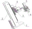
Fig. 1 is a schematic structural view of the present invention;
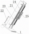
FIG. 2 is a schematic structural diagram of the lifting mechanism;
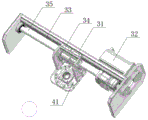
FIG. 3 is a schematic structural view of a horizontal moving mechanism;
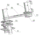
FIG. 4 is a schematic structural diagram of a multi-angle adjusting mechanism and a grabbing mechanism.
Wherein: 1. the base, 2, elevating system, 3, horizontal migration mechanism, 4, angle adjustment mechanism, 5, snatch the mechanism, 6, mechanical clamping jaw, 21, support frame, 22, first motor, 23, first lead screw, 24, first guide rail, 25, first slider, 31, bottom plate, 32, second motor, 33, second guide rail, 34, second slider, 35, second lead screw, 41, support, 42, third motor, 43, drive shaft, 44, fly leaf, 51, base, 52, fourth motor, 53, actuating lever.
Detailed Description
The present invention will be further described with reference to the accompanying drawings.
As shown in fig. 1 to 4, a transverse arm joint manipulator comprises a base 1, an elevating mechanism 2, a horizontal moving mechanism 3, an angle adjusting mechanism 4 and a grabbing mechanism 5, wherein the elevating mechanism 2 is arranged at the upper end of the base 1, the horizontal moving mechanism 3 is arranged at the upper end of the elevating mechanism 2, the angle adjusting mechanism 4 is arranged on the horizontal moving mechanism 3, the grabbing mechanism 5 is connected to one side of the angle adjusting mechanism 4, and a mechanical clamping jaw 6 is connected to the lower end of the grabbing mechanism 5. The lifting mechanism 2 comprises a support frame 21, a first guide rail 24, a first motor 22, a first slide block 25 and a first screw rod 23, the support frame 21 is fixedly installed on the base 1, the first guide rail 24 is fixedly installed on the end face of the support frame 21, the first slide block 25 is arranged on the first guide rail 24, the first motor 22 is arranged at the bottom of the support frame 21, the first motor 22 is connected with the first screw rod 23 positioned in the support frame 21, the first screw rod 23 is connected with the first slide block 25, and the horizontal moving mechanism 3 is installed at the upper end of the first slide block 25; the horizontal moving mechanism 3 comprises a bottom plate 31, a second guide rail 33, a second motor 32, a second sliding block 34 and a second screw rod 35, the bottom plate 31 is fixedly installed on the first sliding block 25, the second guide rail 33 is fixedly installed at the upper end of the bottom plate 31, the second motor 32 is arranged on one side of the second guide rail 33, the second motor 32 is connected with the second screw rod 35 installed in the second guide rail 33, the second screw rod 35 is connected with the second sliding block 34 installed on the second guide rail 33, the angle adjusting mechanism 4 is arranged on the second sliding block 34, the angle adjusting mechanism 4 comprises a support 41, a third motor 42, a driving shaft 43 and a movable plate 44, the support 41 is fixedly installed on the second sliding block, the third motor 42 is arranged at the upper end of the support 41, the driving shaft 43 is connected at the lower end of the third motor 42, the movable plate 44 is connected at the lower end of the; the grabbing mechanism 5 comprises a base 51, a fourth motor 52 and a driving rod, the base 51 is connected with the movable plate 44, the fourth motor 52 is arranged at the upper end of the base 51, the driving rod is connected to the lower end of the fourth motor 52, and the mechanical clamping jaw 6 is connected to the lower end of the driving rod.
In the technical scheme, the up-and-down movement of the horizontal moving mechanism 3 is realized through the matching of the first guide rail 24, the first motor 22, the first slider 25 and the first screw rod 23, the horizontal movement of the multi-angle adjusting mechanism 4 is realized through the matching of the second guide rail 33, the second motor 32, the second slider 34 and the second screw rod 35, the rotation of the grabbing mechanism 5 by taking the bracket as the center is realized through the matching of the third motor 42, the driving shaft 43 and the movable plate 44, the rotation angle of the movable plate 44 is 270 degrees, and the grabbing action of the mechanical clamping jaw 6 is realized through the action of the fourth motor 52 and the driving rod. The utility model discloses a direction and horizontal direction's removal about elevating system, horizontal migration mechanism realize through angle adjustment mechanism that mechanical clamping jaw is 270 degrees rotations in the horizontal direction, compares the not hard up of avoiding the belt pulley with the transmission of belt pulley through lead screw driven mode simultaneously, produces the influence to the precision of position.
The above embodiments are only used to illustrate the technical solution of the present invention, and not to limit the same; although the present invention has been described in detail with reference to the foregoing embodiments, it should be understood by those skilled in the art that: the technical solutions described in the foregoing embodiments may still be modified, or some technical features may be equivalently replaced; such modifications and substitutions do not depart from the spirit and scope of the present invention in its corresponding aspects.
Claims (5)
1. The utility model provides a xarm joint manipulator, includes base, elevating system, horizontal migration mechanism, angle adjustment mechanism and snatchs the mechanism, its characterized in that: the base upper end is equipped with elevating system, the elevating system upper end is equipped with horizontal migration mechanism, be equipped with angle adjustment mechanism on the horizontal migration mechanism, angle adjustment mechanism one side is connected with snatchs the mechanism, it is connected with mechanical clamping jaw to snatch the mechanism lower extreme.
2. The cross-arm joint manipulator of claim 1, wherein: elevating system includes support frame, first guide rail, first motor, first slider and first lead screw, support frame fixed mounting is on the base, fixed mounting has first guide rail on the support frame terminal surface, be equipped with first slider on the first guide rail, the support frame bottom is equipped with first motor, first motor is connected with the first lead screw that is located the support frame, first slider is connected to first lead screw, horizontal migration mechanism is installed to first slider upper end.
3. The cross-arm joint manipulator of claim 1, wherein: the horizontal movement mechanism comprises a bottom plate, a second guide rail, a second motor, a second sliding block and a second screw rod, the bottom plate is fixedly installed on the first sliding block, the second guide rail is fixedly installed at the upper end of the bottom plate, the second motor is arranged on one side of the second guide rail, the second motor is connected with the second screw rod installed in the second guide rail, the second screw rod is connected with the second sliding block installed on the second guide rail, and an angle adjusting mechanism is arranged on the second sliding block.
4. The cross-arm joint manipulator of claim 1, wherein: the angle adjusting mechanism comprises a support, a third motor, a driving shaft and a movable plate, the support is fixedly mounted on the second sliding block, the third motor is arranged at the upper end of the support, the lower end of the third motor is connected with the driving shaft, the lower end of the driving shaft is connected with the movable plate, and the other end of the movable plate is connected with the grabbing mechanism.
5. The cross-arm joint manipulator of claim 1, wherein: snatch mechanism includes base, fourth motor and actuating lever, the base is connected with the fly leaf, and the base upper end is equipped with the fourth motor, the fourth motor lower extreme is connected with the actuating lever, the actuating lever lower extreme is connected with mechanical clamping jaw.
Priority Applications (1)
| Application Number | Priority Date | Filing Date | Title |
|---|---|---|---|
| CN201922118492.5U CN211916825U (en) | 2019-12-02 | 2019-12-02 | Cross arm joint manipulator |
Applications Claiming Priority (1)
| Application Number | Priority Date | Filing Date | Title |
|---|---|---|---|
| CN201922118492.5U CN211916825U (en) | 2019-12-02 | 2019-12-02 | Cross arm joint manipulator |
Publications (1)
| Publication Number | Publication Date |
|---|---|
| CN211916825U true CN211916825U (en) | 2020-11-13 |
Family
ID=73324534
Family Applications (1)
| Application Number | Title | Priority Date | Filing Date |
|---|---|---|---|
| CN201922118492.5U Active CN211916825U (en) | 2019-12-02 | 2019-12-02 | Cross arm joint manipulator |
Country Status (1)
| Country | Link |
|---|---|
| CN (1) | CN211916825U (en) |
Cited By (2)
| Publication number | Priority date | Publication date | Assignee | Title |
|---|---|---|---|---|
| CN112570828A (en) * | 2020-12-05 | 2021-03-30 | 湖南宇晶机器股份有限公司 | Belt type transmission workbench feeding mechanism |
| CN113787199A (en) * | 2021-09-15 | 2021-12-14 | 南京铖联激光科技有限公司 | Shop's powder 3D prints base plate and snatchs equipment |
-
2019
- 2019-12-02 CN CN201922118492.5U patent/CN211916825U/en active Active
Cited By (2)
| Publication number | Priority date | Publication date | Assignee | Title |
|---|---|---|---|---|
| CN112570828A (en) * | 2020-12-05 | 2021-03-30 | 湖南宇晶机器股份有限公司 | Belt type transmission workbench feeding mechanism |
| CN113787199A (en) * | 2021-09-15 | 2021-12-14 | 南京铖联激光科技有限公司 | Shop's powder 3D prints base plate and snatchs equipment |
Similar Documents
| Publication | Publication Date | Title |
|---|---|---|
| CN204997665U (en) | Four degree of freedom low pressure electric appliances transfer robots | |
| CN203697003U (en) | Intelligent robot with high-speed feeding and blanking functions | |
| CN111591754B (en) | Shaft part conveying robot | |
| CN211916825U (en) | Cross arm joint manipulator | |
| CN104816294A (en) | Shifting manipulator | |
| CN210081283U (en) | Automatic grabbing mechanical arm | |
| CN204997674U (en) | Three degree of freedom servo manipulators of transport circuit breaker | |
| CN105800304A (en) | Machine body loading mechanism of limiting switch assembling machine | |
| CN108942909B (en) | Snatch and transport manipulator structure | |
| CN111653510B (en) | Graphite boat conveying equipment and conveying method | |
| CN106379736B (en) | A kind of flexibility punching press plate conveyer | |
| CN215478005U (en) | Turnover mechanism | |
| CN218138150U (en) | Automatic carrying manipulator for machining output rod | |
| CN104608124A (en) | Five-axis mechanical arm for hoisting | |
| CN208467875U (en) | A kind of three-shaft linkage electromagnetic adsorption type handling device | |
| CN204712045U (en) | A kind of shifting mechanical arm | |
| CN116697838A (en) | Visual detection equipment for electronic control module of industrial electronic detonator | |
| CN109434414B (en) | Movable tool of robot assembly demonstration system | |
| CN109506818B (en) | Weight loading device for Young modulus measurement | |
| CN217097806U (en) | Automatic feeding manipulator | |
| CN214454892U (en) | C-shaped spring setting machine | |
| CN212444211U (en) | Novel electric clamping jaw | |
| CN213439729U (en) | Manipulator jaw adjusting rod for loading and unloading | |
| CN211664196U (en) | Rotary carrying device and production line | |
| CN210704888U (en) | Novel three-axis manipulator |
Legal Events
| Date | Code | Title | Description |
|---|---|---|---|
| GR01 | Patent grant | ||
| GR01 | Patent grant |