CN210619360U - Tray feeding device - Google Patents
Tray feeding device Download PDFInfo
- Publication number
- CN210619360U CN210619360U CN201921170607.9U CN201921170607U CN210619360U CN 210619360 U CN210619360 U CN 210619360U CN 201921170607 U CN201921170607 U CN 201921170607U CN 210619360 U CN210619360 U CN 210619360U
- Authority
- CN
- China
- Prior art keywords
- tray
- bottom plate
- feeding
- jacking
- support
- Prior art date
- Legal status (The legal status is an assumption and is not a legal conclusion. Google has not performed a legal analysis and makes no representation as to the accuracy of the status listed.)
- Active
Links
Images


Landscapes
- Specific Conveyance Elements (AREA)
Abstract
The utility model discloses a material device is thrown to tray, throw material mechanism bottom plate and tray subassembly including the material transmission, the device is including throwing the material station, gets material station and tray recovery station, the material transmission is thrown and is equipped with material transmission on the material mechanism bottom plate and throws material mechanism, material transmission is thrown material mechanism and is included that the material snatchs and throw the material subassembly, and tray detection subassembly, transmission are thrown material mechanism and are lapped the support, get material station tray location jacking centre gripping subassembly, and the tray piles up jacking subassembly, and the spacing subassembly of tray transmission piles up jacking centre gripping subassembly and tray and puts in transmission subassembly. The utility model discloses a first-in first-out, the material mode of throwing of duplex position improves the utilization ratio in space effectively, and the cost is reduced has improved work efficiency.
Description
Technical Field
The utility model relates to a material field is thrown to the product, concretely relates to material device is thrown to tray.
Background
The stacking is a common feeding mode in daily production, the stacker crane can be intelligently operated and managed, is simple and convenient to master, can reduce labor force, and reduces labor intensity, so that the stacker crane is widely applied to material feeding.
SUMMERY OF THE UTILITY MODEL
For solving the above-mentioned problem that exists among the prior art, the utility model provides a material device is thrown to tray.
The technical scheme of the utility model as follows: a tray feeding device comprises a material conveying feeding mechanism bottom plate and a tray assembly, the device comprises a feeding station, a material taking station and a tray recovery station, the feeding station and the tray recovery station are respectively arranged on two sides above the material conveying feeding mechanism bottom plate, the material taking station is arranged between the feeding station and the tray recovery station, the material conveying feeding mechanism is arranged on the material conveying feeding mechanism bottom plate, the material conveying feeding mechanism comprises a material grabbing feeding assembly, a material taking station tray positioning jacking clamping assembly, a tray stacking jacking assembly, a tray conveying limiting assembly, a tray stacking feeding jacking clamping assembly and a tray stacking conveying assembly, the tray stacking jacking assembly and the tray stacking feeding jacking clamping assembly are arranged at the feeding station and the tray recovery station, the material taking station tray positioning clamping assembly and the material grabbing feeding assembly are arranged at the material taking station, the tray stack transmission assembly is used for connecting a feeding station, a material taking station and a tray recovery station, and the tray transmission limiting assembly is arranged on a central axis of a bottom plate of the material transmission feeding mechanism.
The material conveying and feeding mechanism further comprises a conveying and feeding mechanism cover plate support, a conveying and feeding mechanism cover plate and a tray detection assembly, the conveying and feeding mechanism cover plate support is arranged on a bottom plate of the material conveying and feeding mechanism, the conveying and feeding mechanism cover plate is arranged on the conveying and feeding mechanism cover plate support, and the tray detection assembly is arranged on the conveying and feeding mechanism cover plate.
The material snatchs and throws the material subassembly including snatching material Y to moving servo module, snatch material X to moving servo module, snatch material tool subassembly, snatch material X to moving servo module support and snatch material tool subassembly support, snatch material X and fix the top at material transmission feeding mechanism bottom plate to moving servo module support, snatch material X and be equipped with on the servo module support of snatching material X to moving servo module, it snatchs material Y to moving servo module to be connected with on the servo module to snatch material X, it snatchs material tool subassembly support to being connected with on the servo module of moving to snatch material Y, it snatchs material tool subassembly to being equipped with on the material tool subassembly support to snatch.
Get material station tray location jacking centre gripping subassembly and include backing plate, backing plate support, first jacking cylinder, first support material piece, first guide strip, first upper and lower regulating block, first fore-and-aft regulating block and first cylinder linking bridge, the backing plate is fixed in the top of material transmission feeding mechanism bottom plate, be equipped with the backing plate support on the backing plate, be equipped with first jacking cylinder on the backing plate support, first jacking cylinder top is connected with first cylinder linking bridge, first cylinder linking bridge top symmetry is equipped with two first fore-and-aft regulating blocks, be equipped with first upper and lower regulating block on the first fore-and-aft regulating block, one side of first upper and lower regulating block is equipped with first guide strip, the below of first guide strip is fixed with first support material piece.
The tray stacking and jacking assembly comprises a base plate, an air cylinder and a tray jacking plate, wherein the base plate is fixed above a bottom plate of the material conveying and feeding mechanism, the air cylinder is arranged on the base plate, and the tray jacking plate is connected above the air cylinder.
The tray transmission limiting assembly comprises a bottom plate, a cylinder support, a material blocking cylinder and a material blocking block, wherein the bottom plate is fixed above a bottom plate of the material transmission feeding mechanism, the cylinder support is arranged on the bottom plate, the material blocking cylinder is fixed on the cylinder support, and the material blocking block is connected above the material blocking cylinder.
The tray stacking and feeding jacking and clamping assembly comprises two jacking clamping pieces, a linear guide rail, two bottom plate supports, a first driving servo motor, a motor mounting plate, a driving motor synchronous wheel, a first synchronous belt, a driven wheel and a synchronous belt driving support which are symmetrically arranged, wherein the linear guide rail is fixed on a bottom plate of a material conveying and feeding mechanism, the linear guide rail is provided with the bottom plate supports, the jacking clamping pieces are arranged on the bottom plate supports, the two bottom plate supports are connected with the synchronous belt driving support through a first synchronous belt, one side of each bottom plate support is connected with the synchronous belt driving support, the synchronous belt driving support is connected with the first synchronous belt, the driven wheel and the driving motor synchronous wheel are connected with each other through the first synchronous belt, the first servo motor is connected below the driving motor synchronous wheel and fixed on the motor mounting plate, the jacking clamping piece comprises a cylinder base plate, a second jacking cylinder, a second cylinder connecting support, a front adjusting block and a rear adjusting block of the second, an upper adjusting block and a lower adjusting block of the second, a second material guiding strip and a second material supporting block, the cylinder base plate is arranged on the bottom plate support, the second jacking cylinder is arranged on the cylinder base plate, the second cylinder connecting support is connected above the second jacking cylinder, the two front adjusting blocks and the rear adjusting block of the second are symmetrically arranged on the second cylinder connecting support, the upper adjusting block and the lower adjusting block of the second are arranged on the front adjusting block and the rear adjusting block of the second, the second material guiding strip is arranged on one side of the upper adjusting block and the lower adjusting block of the second, and the second material guiding strip is fixed below the second material supporting block.
The tray is piled up and is put in jacking centre gripping subassembly still includes position photoelectric sensor support, position photoelectric sensor response piece, one side of bottom plate support is equipped with position photoelectric sensor support, be equipped with position photoelectric sensor on the position photoelectric sensor support, be equipped with position photoelectric sensor response piece on the bottom plate support.
The tray is piled transmission assembly and is included the hold-in range action wheel, and the hold-in range is from the driving wheel, and the second hold-in range, the transmission support, the transmission shaft fixed plate, the transmission shaft, second servo motor, transmission support and second servo motor fix the top of throwing material mechanism bottom plate at material transmission, be fixed with the transmission shaft fixed plate on the transmission support, be equipped with the transmission shaft on the transmission shaft fixed plate, be equipped with hold-in range action wheel and hold-in range on the transmission shaft from the driving wheel, hold-in range action wheel and hold-in range are connected through the second hold-in range between the driving wheel, second servo motor passes through belt drive.
The material taking stations are two and are arranged adjacently.
The utility model has the characteristics of it is following:
1. the feeding mode of the tray feeding device is adopted, the turnover rate in the production process is reduced, the production efficiency is improved, and the working intensity of workers is reduced.
2. The double-station feeding area is adopted, the feeding switching time is shortened, the feeding amount is increased, the production working hours are effectively saved, the production period is shortened, the production efficiency is effectively improved, the utilization rate of the space is improved, the waste of the structural space is reduced, and the equipment cost is reduced.
3. The double-channel servo motor triaxial module is adopted, and the implementation of high-precision positioning feeding is effectively realized; the reduced feeding positioning error can be controlled below +/-0.05 mm, and the uncontrollable factors in the production process are reduced.
4. A reverse feeding mode is adopted, the effect of first-in first-out is achieved, the production quality requirement is improved, and the production defects are reduced.
5. The feeding mode of the tray feeding device is adopted, intelligent production is achieved, controllability in the production process is improved, production efficiency is improved, working hours, personnel and quality cost are reduced, and cost controllability is achieved.
Drawings
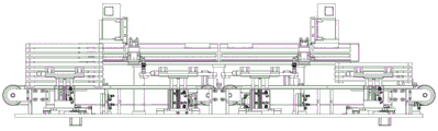
Fig. 1 is a schematic structural diagram of the present invention;
fig. 2 is a schematic structural diagram of the present invention;
fig. 3 is a schematic structural diagram of the present invention;
fig. 4 is an exploded view of the present invention;
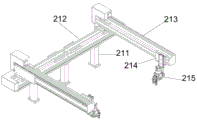
FIG. 5 is a schematic structural view of a material grasping and feeding assembly;
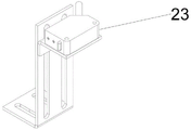
FIG. 6 is a schematic structural view of a pallet detection assembly;
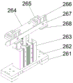
FIG. 7 is a schematic structural view of a reclaiming station tray positioning jacking clamping assembly;
FIG. 8 is a schematic structural view of a pallet stack jacking assembly;
FIG. 9 is a schematic structural view of a tray transfer stop assembly;
FIG. 10 is a schematic structural view of a pallet stack launch jacking clamp assembly;
FIG. 11 is a schematic structural view of a pallet stack transfer assembly;
in the figure: 1-a tray component, 2-a material conveying and feeding mechanism, 3-a feeding station, 4-a material taking station, 5-a tray recovery station, 21-a material grabbing and feeding component, 22-a transmission belt guide, 23-a tray detection component, 24-a conveying and feeding mechanism cover plate, 25-a conveying and feeding mechanism cover plate support, 26-a material taking station tray positioning, jacking and clamping component, 27-a tray stacking, jacking component, 28-a tray conveying and limiting component, 29-a tray stacking, jacking and clamping component, 30-a tray stacking, conveying component, 31-a material conveying and feeding mechanism bottom plate, 211-a material grabbing X-direction moving servo module support, 212-a material grabbing X-direction moving servo module, 213-a material grabbing Y-direction moving servo module, 214-a material grabbing jig component support, 215-grabbing material jig assembly, 261-bottom plate, 262-bottom plate support, 263-first jacking cylinder, 264-first cylinder connecting support, 265-first front and rear adjusting block, 266-first upper and lower adjusting block, 267-first guide strip, 268-first support block, 271-bottom plate, 272-cylinder, 273-tray jacking plate, 281-bottom plate, 282-cylinder support, 283-stop cylinder, 284-stop block, 2901-linear guide rail, 2902-bottom plate support, 2903-synchronous belt driving support, 2904-first synchronous belt, 2905-driven wheel, 2906-driving motor synchronous wheel, 2907-first servo motor, 2908-motor mounting plate, 2909-cylinder plate, 2910-second jacking cylinder, 2911-second cylinder connecting support, 2912-second front and back adjusting block, 2913-second upper and lower adjusting block, 2914-second material guiding strip, 2915-second material supporting block, 2916-position photoelectric sensor support, 2917-position photoelectric sensor, 2918-position photoelectric sensor sensing piece, 301-transmission support, 302-transmission shaft fixing plate, 303-transmission shaft, 304-synchronous belt driven wheel, 305-synchronous belt driving wheel, 306-second synchronous belt, 307-second servo motor, 31-material transmission feeding mechanism bottom plate.
Detailed Description
The present invention will be further explained with reference to the accompanying drawings:
as shown in fig. 1-4, a tray feeding device comprises a material conveying feeding mechanism bottom plate 31 and a tray assembly 1, the device comprises a feeding station 3, two material taking stations 4 and a tray recovery station 5, the feeding station 3 and the tray recovery station 5 are respectively arranged at two sides above the material conveying feeding mechanism bottom plate 4, the two material taking stations 4 are arranged between the feeding station 3 and the tray recovery station 5, the material conveying feeding mechanism bottom plate 31 is provided with a material conveying feeding mechanism 2, the material conveying feeding mechanism 2 comprises a material grabbing feeding assembly 21, a material taking station tray positioning jacking clamping assembly 26, a tray stacking jacking assembly 27, a tray conveying limiting assembly 28, a tray stacking jacking clamping assembly 29 and a tray stacking conveying assembly 30,
the tray stacking jacking assembly 27 and the tray stacking, throwing jacking and clamping assembly 29 are arranged at the feeding station 3 and the tray recovery station 5, the material taking station tray positioning jacking assembly 26 and the material grabbing, throwing assembly 21 are arranged at the material taking station 4, the tray stack transmission assembly 30 is used for being connected with the feeding station 3, the material taking station 4 and the tray recovery station 5, and the tray transmission limiting assembly 28 is arranged on a central axis of a material transmission and throwing mechanism bottom plate 31.
The material conveying and feeding mechanism 2 further comprises a conveying and feeding mechanism cover plate support 25, a conveying and feeding mechanism cover plate 24 and a tray detection assembly 23, the conveying and feeding mechanism cover plate support 25 is arranged on the material conveying and feeding mechanism bottom plate 31, the conveying and feeding mechanism cover plate 24 is arranged on the conveying and feeding mechanism cover plate support 25, and the tray detection assembly 23 is arranged on the conveying and feeding mechanism cover plate 24.
As shown in fig. 5, the material grabbing and feeding assembly 21 includes a grabbing material X to a moving servo module support 211, a grabbing material X to a moving servo module 212, a grabbing material Y to a moving servo module 213, a grabbing material jig assembly support 214 and a grabbing material jig assembly 215, the grabbing material X to the moving servo module support 211 is fixed above the material conveying and feeding mechanism bottom plate 31, the grabbing material X to the moving servo module support 211 is provided with the grabbing material X to the moving servo module 212, the grabbing material X to the moving servo module 212 is connected with the grabbing material Y to the moving servo module 213, the grabbing material Y to the moving servo module 213 is connected with the grabbing material jig assembly support 214, and the grabbing material jig assembly support 214 is provided with the grabbing material jig assembly 215.
As shown in fig. 7, the picking station pallet positioning and jacking clamp assembly includes a bottom plate 261, a bottom plate bracket 262, a first jacking cylinder 263, a first cylinder connecting bracket 264, a first front-back adjusting block 265, a first upper-lower adjusting block 266, a first guiding strip 267 and a first material supporting block 268, the bottom cushion plate 261 is fixed above the bottom plate 31 of the material conveying and feeding mechanism, a bottom cushion plate bracket 262 is arranged on the bottom cushion plate 261, a first jacking cylinder 263 is arranged on the bottom cushion plate bracket 262, a first cylinder connecting bracket 264 is connected above the first jacking cylinder 263, two first front and rear adjusting blocks 265 are symmetrically arranged above the first cylinder connecting bracket 264, the first front-back adjusting block 265 is provided with a first up-down adjusting block 266, one side of the first up-down adjusting block 266 is provided with a first material guiding strip 267, and a first material supporting block 268 is fixed below the first material guiding strip 267.
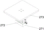
As shown in fig. 8, the tray stacking and jacking assembly 27 includes a backing plate 271, an air cylinder 272 and a tray jacking plate 273, the backing plate is fixed above the bottom plate 31 of the material conveying and feeding mechanism, the air cylinder 272 is arranged on the backing plate 271, and the tray jacking plate 273 is connected above the air cylinder 272.
As shown in fig. 9, the tray conveying and limiting assembly 28 includes a bottom plate 281, an air cylinder support 282, a material blocking air cylinder 283 and a material blocking block 284, the bottom plate 281 is fixed above the bottom plate 31 of the material conveying and feeding mechanism, the air cylinder support 282 is arranged on the bottom plate 281, the material blocking air cylinder 283 is fixed on the air cylinder support 282, and the material blocking block 284 is connected above the material blocking air cylinder 283.
As shown in fig. 10, the tray stacking, dropping, lifting and clamping assembly 29 includes two lifting and clamping members symmetrically disposed, a linear guide 2901, two bottom plate brackets 2902, a first driving servo motor 2907, a motor mounting plate 2908, a driving motor synchronous wheel 2906, a first synchronous belt 2904, a driven wheel 2905 and a synchronous belt driving bracket 2903, the linear guide 2901 is fixed on the material conveying and feeding mechanism bottom plate 31, the linear guide 2901 is provided with the bottom plate brackets 2902, the bottom plate brackets 2902 are provided with the lifting and clamping members, the two bottom plate brackets 2902 are connected through the first synchronous belt 2904 and the synchronous belt driving bracket 2903, one side of the bottom plate bracket 2902 is connected with the synchronous belt driving bracket 2903, the synchronous belt driving bracket 2903 is connected with the first synchronous belt 2904, the driven wheel 2905 and the driving motor synchronous wheel 2906 are connected through the first synchronous belt 2904, the first servo motor 2907 is connected below the driving motor synchronous wheel 2906, the first servo motor 2907 is fixed to the motor mounting plate 2908.
The jacking clamping piece comprises an air cylinder base plate 2909, a second jacking air cylinder 2910, a second air cylinder connecting support 2911, a second front-back adjusting block 2912, a second upper-lower adjusting block 2913, a second material guiding strip 2914 and a second material supporting block 2915, the air cylinder base plate 2909 is arranged on the bottom plate support 2902, the second jacking air cylinder 2910 is arranged on the air cylinder base plate 2909, the second air cylinder connecting support 2912 is connected to the upper portion of the second jacking air cylinder 2911, the two second front-back adjusting blocks 2913 are symmetrically arranged on the second air cylinder connecting support 2912, the second upper-lower adjusting block 2914 is arranged on the second front-back adjusting block 2913, the second material guiding strip 2915 is arranged on one side of the second upper-lower adjusting block 2914, and a second material supporting block 2916 is fixed below the second material guiding strip 2915.
The tray stacking, releasing, jacking and clamping assembly 29 further includes a position photoelectric sensor support 2916, a position photoelectric sensor 2917 and a position photoelectric sensor sensing chip 2918, wherein the position photoelectric sensor support 2916 is disposed on one side of the bottom plate support 2902, the position photoelectric sensor 2917 is disposed on the position photoelectric sensor support 2916, and the position photoelectric sensor sensing chip 2918 is disposed on the bottom plate support 2902.
As shown in fig. 11, the tray stack conveying assembly 30 includes a conveying support 301, a conveying shaft fixing plate 302, a conveying shaft 303, a synchronous belt driving wheel 305, a synchronous belt driven wheel 304, a second synchronous belt 306 and a second servo motor 307, the conveying support 301 and the second servo motor 307 are fixed above the material conveying feeding mechanism bottom plate 31, the conveying support 301 is fixed with the conveying shaft fixing plate 302, the conveying shaft fixing plate 302 is provided with the conveying shaft 303, the conveying shaft 303 is provided with the synchronous belt driving wheel 305 and the synchronous belt driven wheel 304, the synchronous belt driving wheel 305 and the synchronous belt driven wheel 304 are connected through the second synchronous belt 306, the second servo motor 307 drives the synchronous belt driving wheel 305 to rotate through a belt, and the second synchronous belt 306 is connected with the conveying belt guide 22.
The working process of the utility model is as follows:
firstly, when the equipment is started, the stacked feeding tray is put into the feeding station 3, the terminal controller receives a feeding completion instruction transmitted by the photoelectric sensor of the tray detection assembly 23, and the terminal controller sends an instruction to the tray stacking jacking assembly 27, and then the air cylinder 272 of the tray stacking jacking assembly 27 jacks up the feeding tray in the feeding station 11 to jack up the feeding tray. Meanwhile, the terminal controller sends an instruction to the tray stacking, releasing, jacking and clamping assembly 29, a first servo motor 2907 of the tray stacking, releasing, jacking and clamping assembly 29 drives a driving motor synchronous wheel 2906, a first synchronous belt 2904 and a driven wheel 2905 to drive a synchronous belt driving support 2903 to push a bottom plate support 2902 to move on a linear guide rail 2901, and a second material supporting block 2915 is separated towards two sides; meanwhile, the position photoelectric sensor sensing piece 2918 is mounted on the bottom plate support 2902 and moves along with the bottom plate support 2902, the photoelectric sensor sensing piece 2918 triggers the position photoelectric sensor 2917 to transmit a position signal to the terminal controller in the moving process, at this time, the tray stacking and jacking assembly 27 jacks up and supports the feeding tray in the feeding station 3, and the second jacking cylinders 2910 on the two sides of the tray stacking, launching and jacking assembly 29 are pushed up and jacked out. The terminal controller sends an instruction to the tray stacking, releasing, jacking and clamping assembly 29 again, and the first servo motor 2907 of the tray stacking, releasing, jacking and clamping assembly 29 drives the synchronous wheel 2906 of the driving motor, drives the first synchronous belt 2904 and the driven wheel 2905, and drives the synchronous belt driving support 2903 to push the bottom plate support 2902 to move on the linear guide 2901; the second material supporting block 2915 is clamped inwards to clamp the feeding tray in the feeding station 3, at this time, the second material supporting block 2915 supports the tray at a position on the feeding tray stack, and meanwhile, the tray lifting plate 273 of the tray stacking and lifting assembly 27 supports one feeding tray at the bottom to move downwards along with the air cylinder 272 so as to feed the feeding tray onto the tray stack transmission assembly 30; one feeding tray is conveyed out in a circulating mode in sequence. After the tray stacking, throwing and jacking clamping assembly 29 drops the throwing trays onto the tray stack conveying assembly 30; the terminal controller sends an instruction to the tray stack transmission assembly 30 to drive the second servo motor 307 to drive the synchronous belt driving wheel 305, the second synchronous belt 306, the transmission shaft 303 and the synchronous belt driven wheel 304 to convey the feeding tray to the position of the material taking station 4; at this time, the terminal controller sends an instruction to the tray transmission limiting assembly 28 at the material taking station 4, and the tray transmission limiting assembly 28 blocks the feeding tray. Meanwhile, the terminal controller sends an instruction to the material taking station tray positioning and jacking clamping assemblies 26, and at the moment, the two symmetrically arranged material taking station tray positioning and jacking clamping assemblies 26 jack the material taking station 4 position feeding tray. The terminal controller sends an instruction to the servo motor driver of the material grabbing and feeding module 21 for driving the two modules to cooperate with each other, so as to drive the material grabbing jig module 215 to sequentially feed the materials on the feeding tray at the position of the material taking station 4 into the production line for production; and sequentially and circularly feeding a material into a production line for production. When the material on the feeding tray at the position of the material taking station 4 is completely fed, the terminal controller sends an instruction to the material taking station tray positioning and jacking clamping component 26, the material taking station tray positioning and jacking clamping component 26 descends, the tray transmission limiting component 28 at the material taking station descends, the tray transmission limiting component 28 at the tray recovery station 5 ascends to block, the tray stack transmission component 30 transmits the feeding tray to the tray recovery station 5, the terminal controller sends an instruction to the tray stacking and jacking component 27, at the moment, the air cylinder 272 of the tray stacking and jacking component 27 jacks up the feeding tray in the tray recovery station 5, meanwhile, the first servo motor 2907 of the tray stacking and jacking clamping component 29 drives the driving motor synchronous wheel 2906 to drive the first synchronous belt 2904 and the driven wheel 2905 to drive the synchronous belt driving bracket 2903 to push the bottom plate bracket 2902 to move on the linear guide rail 2901, the second material supporting block 2915 is separated towards two sides, the second jacking cylinders 2910 on two sides of the tray stacking, throwing and jacking clamping assembly 29 descend, then the terminal controller sends an instruction again to the tray stacking, throwing and jacking clamping assembly 29, the first servo motor 2907 of the tray stacking, throwing and jacking clamping assembly 29 drives the driving motor synchronizing wheel 2906 to drive the first synchronizing belt 2904 and the driven wheel 2905 to drive the synchronizing belt driving support 2903 to push the bottom plate support 2902 to move on the linear guide rail 2901, the second material supporting block 2915 clamps the material feeding tray to be recovered inwards, and the second jacking cylinders 2910 on two sides of the tray stacking, throwing and jacking clamping assembly 29 lift the material feeding tray in the tray recovery stacking area 14 upwards; at the moment, the empty feeding trays are stacked and recycled after feeding is finished; and sequentially and circularly stacking and recovering an empty feeding tray after feeding.
Claims (10)
1. The utility model provides a material device is thrown to tray, includes that material transmission throws material mechanism bottom plate (31) and tray subassembly (1), its characterized in that: the device comprises a feeding station (3), a material taking station (4) and a tray recovery station (5), wherein the feeding station (3) and the tray recovery station (5) are respectively arranged at two sides above a material conveying and feeding mechanism bottom plate (31), the material taking station (4) is arranged between the feeding station (3) and the tray recovery station (5), a material conveying and feeding mechanism (2) is arranged on the material conveying and feeding mechanism bottom plate (31), the material conveying and feeding mechanism (2) comprises a material grabbing and feeding component (21), a material taking station tray positioning and jacking clamping component (26), a tray stacking and jacking component (27), a tray conveying limiting component (28), a tray stacking and feeding jacking clamping component (29) and a tray stack conveying component (30), the tray stacking and feeding jacking component (27) and the tray stacking and feeding clamping component (29) are arranged at the feeding station (3) and the tray recovery station (5), the material taking station tray positioning jacking clamping assembly (26) and the material grabbing and feeding assembly (21) are arranged at the material taking station (4), the tray stack transmission assembly (30) is used for connecting the material feeding station (3), the material taking station (4) and the tray recovery station (5), and the tray transmission limiting assembly (28) is arranged on a central axis of a material transmission and feeding mechanism bottom plate (31).
2. A pallet feeding device as claimed in claim 1, wherein: the material conveying and feeding mechanism (2) further comprises a conveying and feeding mechanism cover plate support (25), a conveying and feeding mechanism cover plate (24) and a tray detection assembly (23), the conveying and feeding mechanism cover plate support (25) is arranged on a material conveying and feeding mechanism bottom plate (31), the conveying and feeding mechanism cover plate support (25) is provided with a conveying and feeding mechanism cover plate (24), and the conveying and feeding mechanism cover plate (24) is provided with the tray detection assembly (23).
3. A pallet feeding device as claimed in claim 1, wherein: the material grabbing and feeding assembly (21) comprises a material grabbing X-direction moving servo module bracket (211), a material grabbing X-direction moving servo module (212), a material grabbing Y-direction moving servo module (213), a material grabbing jig assembly bracket (214) and a material grabbing jig assembly (215), the material grabbing X-direction moving servo module bracket (211) is fixed above a material conveying and feeding mechanism bottom plate (31), the material grabbing X-direction moving servo module bracket (211) is provided with a material grabbing X-direction moving servo module (212), the material grabbing X-direction moving servo module (212) is connected with a material grabbing Y-direction moving servo module (213), the material grabbing Y-direction moving servo module (213) is connected with a material grabbing jig component support (214), and a material grabbing jig component (215) is arranged on the material grabbing jig component support (214).
4. A pallet feeding device as claimed in claim 1, wherein: the material taking station tray positioning and jacking clamping assembly comprises a bottom base plate (261), a bottom base plate support (262), a first jacking cylinder (263), a first cylinder connecting support (264), a first front and rear adjusting block (265), a first upper and lower adjusting block (266), a first material guiding strip (267) and a first material supporting block (268), wherein the bottom base plate (261) is fixed above a material conveying and feeding mechanism bottom plate (31), the bottom base plate (261) is provided with the bottom base plate support (262), the bottom base plate support (262) is provided with the first jacking cylinder (263), the first jacking cylinder (263) is connected above the first air cylinder connecting support (264), the two first front and rear adjusting blocks (265) are symmetrically arranged above the first air cylinder connecting support (264), the first front and rear adjusting block (265) is provided with the first upper and lower adjusting block (266), one side of the first upper and lower adjusting block (266) is provided with the first material guiding strip (267), a first material supporting block (268) is fixed below the first material guiding strip (267).
5. A pallet feeding device as claimed in claim 1, wherein: the tray stacking and jacking assembly (27) comprises a base plate (271), a cylinder (272) and a tray jacking plate (273), wherein the base plate is fixed above a material conveying and feeding mechanism bottom plate (31), the cylinder (272) is arranged on the base plate (271), and the tray jacking plate (273) is connected above the cylinder (272).
6. A pallet feeding device as claimed in claim 1, wherein: the tray transmission limiting assembly (28) comprises a bottom plate (281), an air cylinder support (282), a material blocking air cylinder (283) and a material blocking block (284), wherein the bottom plate (281) is fixed above a material transmission feeding mechanism bottom plate (31), the air cylinder support (282) is arranged on the bottom plate (281), the material blocking air cylinder (283) is fixed on the air cylinder support (282), and the material blocking block (284) is connected above the material blocking air cylinder (283).
7. A pallet feeding device as claimed in claim 1, wherein: the tray stacking, releasing, lifting and clamping assembly (29) comprises two lifting and clamping pieces, a linear guide rail (2901), two bottom plate brackets (2902), a first servo motor (2907), a motor mounting plate (2908), a driving motor synchronous wheel (2906), a first synchronous belt (2904), a driven wheel (2905) and a synchronous belt driving bracket (2903), wherein the linear guide rail (2901) is fixed on a bottom plate (31) of the material conveying and feeding mechanism, the bottom plate bracket (2902) is arranged on the linear guide rail (2901), the lifting and clamping pieces are arranged on the bottom plate bracket (2902), the two bottom plate brackets (2902) are connected with the synchronous belt driving bracket (2903) through the first synchronous belt (2904), one side of the bottom plate bracket (2902) is connected with the synchronous belt driving bracket (2903), and the synchronous belt driving bracket (2903) is connected with the first synchronous belt (2904), the driven wheel (2905) is connected with the driving motor synchronous wheel (2906) through a first synchronous belt (2904), a first servo motor (2907) is connected below the driving motor synchronous wheel (2906), the first servo motor (2907) is fixed on a motor mounting plate (2908),
the jacking clamping piece comprises a cylinder backing plate (2909), a second jacking cylinder (2910), a second cylinder connecting support (2911), a second front-back adjusting block (2912), a second upper-lower adjusting block (2913), a second material guiding strip (2914) and a second material supporting block (2915), the bottom plate bracket (2902) is provided with an air cylinder base plate (2909), the air cylinder base plate (2909) is provided with a second jacking air cylinder (2910), a second cylinder connecting bracket (2911) is connected above the second jacking cylinder (2910), two second front and back adjusting blocks (2912) are symmetrically arranged on the second cylinder connecting support (2911), a second up-and-down adjusting block (2913) is arranged on the second front-and-back adjusting block (2912), one side of the second up-down adjusting block (2913) is provided with a second material guiding strip (2914), a second material supporting block (2915) is fixed below the second material guiding strip (2914).
8. The tray feeding device according to claim 7, wherein: the tray stacking, releasing, jacking and clamping assembly (29) further comprises a position photoelectric sensor support (2916), a position photoelectric sensor (2917) and a position photoelectric sensor sensing piece (2918), wherein the position photoelectric sensor support (2916) is arranged on one side of the bottom plate support (2902), the position photoelectric sensor (2917) is arranged on the position photoelectric sensor support (2916), and the position photoelectric sensor sensing piece (2918) is arranged on the bottom plate support (2902).
9. A pallet feeding device as claimed in claim 1, wherein: the tray stack transmission assembly (30) comprises a transmission bracket (301), a transmission shaft fixing plate (302), a transmission shaft (303), a synchronous belt driving wheel (305), a synchronous belt driven wheel (304), a second synchronous belt (306) and a second servo motor (307), the transmission bracket (301) and the second servo motor (307) are fixed above the material transmission feeding mechanism bottom plate (31), a transmission shaft fixing plate (302) is fixed on the transmission bracket (301), a transmission shaft (303) is arranged on the transmission shaft fixing plate (302), a synchronous belt driving wheel (305) and a synchronous belt driven wheel (304) are arranged on the transmission shaft (303), the synchronous belt driving wheel (305) and the synchronous belt driven wheel (304) are connected through a second synchronous belt (306), the second servo motor (307) drives a synchronous belt driving wheel (305) to rotate through a belt, and the second synchronous belt (306) is connected with a conveying belt guide piece (22).
10. A pallet feeding device as claimed in claim 1, wherein: the material taking stations (4) are two, and the two material taking stations (4) are arranged adjacently.
Priority Applications (1)
| Application Number | Priority Date | Filing Date | Title |
|---|---|---|---|
| CN201921170607.9U CN210619360U (en) | 2019-07-24 | 2019-07-24 | Tray feeding device |
Applications Claiming Priority (1)
| Application Number | Priority Date | Filing Date | Title |
|---|---|---|---|
| CN201921170607.9U CN210619360U (en) | 2019-07-24 | 2019-07-24 | Tray feeding device |
Publications (1)
| Publication Number | Publication Date |
|---|---|
| CN210619360U true CN210619360U (en) | 2020-05-26 |
Family
ID=70750729
Family Applications (1)
| Application Number | Title | Priority Date | Filing Date |
|---|---|---|---|
| CN201921170607.9U Active CN210619360U (en) | 2019-07-24 | 2019-07-24 | Tray feeding device |
Country Status (1)
| Country | Link |
|---|---|
| CN (1) | CN210619360U (en) |
Cited By (2)
| Publication number | Priority date | Publication date | Assignee | Title |
|---|---|---|---|---|
| CN110316536A (en) * | 2019-07-24 | 2019-10-11 | 珠海市鼎谌智能科技有限公司 | A kind of pallet charging device |
| CN112340425A (en) * | 2020-11-03 | 2021-02-09 | 武汉智汇芯科技有限公司 | Full-automatic laser Bar feeding and discharging method and device |
-
2019
- 2019-07-24 CN CN201921170607.9U patent/CN210619360U/en active Active
Cited By (3)
| Publication number | Priority date | Publication date | Assignee | Title |
|---|---|---|---|---|
| CN110316536A (en) * | 2019-07-24 | 2019-10-11 | 珠海市鼎谌智能科技有限公司 | A kind of pallet charging device |
| CN110316536B (en) * | 2019-07-24 | 2024-02-23 | 珠海市鼎谌智能科技有限公司 | Pallet feeding device |
| CN112340425A (en) * | 2020-11-03 | 2021-02-09 | 武汉智汇芯科技有限公司 | Full-automatic laser Bar feeding and discharging method and device |
Similar Documents
| Publication | Publication Date | Title |
|---|---|---|
| CN110316536B (en) | Pallet feeding device | |
| CN109501115B (en) | Feeding and discharging system of injection molding machine | |
| CN210619360U (en) | Tray feeding device | |
| CN109894739A (en) | Fully-automatic laser marking press equipment for cylinder circle | |
| CN207645370U (en) | A kind of full-automatic cardboard Palletizer | |
| CN201186351Y (en) | Intelligent arrangement apparatus | |
| CN213622289U (en) | Charging tray blanking equipment | |
| CN217837512U (en) | Continuous feeding mechanism | |
| CN108747048B (en) | Automatic feeding and discharging laser processing system and laser processing method | |
| CN216470884U (en) | Film tearing and blanking machine for glass | |
| CN217555153U (en) | Full-automatic robot bottle unloading machine | |
| CN114572698B (en) | Automatic stacking equipment for tobacco packages | |
| CN110842071A (en) | Truss type robot stamping system | |
| CN113843417B (en) | Automatic feeding and discharging production line of boat pushing furnace | |
| CN215905365U (en) | Automatic workpiece feeding device | |
| CN213650806U (en) | Intelligent three-dimensional storage cotton distribution conveying system | |
| CN212502541U (en) | Automatic feeding and discharging equipment of pad printing machine | |
| CN213111579U (en) | Automatic feeding and recycling device for tray | |
| CN212923542U (en) | Insulation board buttress group separation transfer system | |
| CN210548821U (en) | Full-automatic laser engraving device for engine cylinder ring | |
| CN210794977U (en) | Full-automatic stacking device for PP (polypropylene) plates | |
| CN114313766A (en) | Automatic feeding and discharging mechanism of production line | |
| CN211545064U (en) | Automatic material machine of receiving of supplying of full-automatic ink jet numbering machine Tray | |
| CN210647965U (en) | Automatic workpiece stamping carrying and film laminating system | |
| CN106865195B (en) | Panel transfer robot system |
Legal Events
| Date | Code | Title | Description |
|---|---|---|---|
| GR01 | Patent grant | ||
| GR01 | Patent grant |