CN210615721U - Rotary disc type automatic screw locking device - Google Patents
Rotary disc type automatic screw locking device Download PDFInfo
- Publication number
- CN210615721U CN210615721U CN201921151967.4U CN201921151967U CN210615721U CN 210615721 U CN210615721 U CN 210615721U CN 201921151967 U CN201921151967 U CN 201921151967U CN 210615721 U CN210615721 U CN 210615721U
- Authority
- CN
- China
- Prior art keywords
- plate
- feeding
- screw
- machine table
- discharging
- Prior art date
- Legal status (The legal status is an assumption and is not a legal conclusion. Google has not performed a legal analysis and makes no representation as to the accuracy of the status listed.)
- Active
Links
Images


Abstract
The utility model relates to a turntable type automatic screw locking device, which comprises a machine table; the turntable conveying mechanism is arranged on the machine table and used for bearing and conveying products; the detection pressing mechanism is arranged on the machine table and used for detecting and pressing the product; the screw locking mechanism is arranged on the machine table and used for locking screws; the spring plate conveying mechanism is used for conveying the spring plates to the screw locking mechanism; the discharging mechanism is arranged on the machine table and used for discharging the product; and the feeding mechanism is arranged on the machine table and used for providing the elastic sheet for the elastic sheet conveying mechanism. The utility model discloses set up lock screw mechanism, shell fragment conveying mechanism, discharge mechanism, can be automatically with screw locking for the shell fragment to the product on, lock screw mechanism is when taking the shell fragment, and the criticism head of electricity criticizing takes the screw to penetrate the screw hole that the shell fragment was predetermine, and the profile modeling adsorbs the head and can cause the part of interference to strut and adsorb the shell fragment with the shell fragment, on fixing the product with shell fragment locking fast, has improved work efficiency, has reduced manufacturing cost, has guaranteed the yields.
Description
Technical Field
The invention relates to the field of screw locking machines, in particular to a rotary disc type automatic screw locking device.
Background
In the manufacturing industry, a wide variety of products are involved. Some more complex products require multiple parts to be manufactured and assembled into a complete product. When the components are assembled, the components are connected with each other by screws, nuts and the like. In a traditional operation mode, a common screwdriver or an electric screwdriver is generally adopted manually to perform screwing operation of screws. With advances in technology, manufacturing industries are beginning to gradually shift to automation. At present, equipment capable of automatically locking screws begins to appear on the market, but most of the equipment capable of automatically locking screws can only lock screws on products without interference on a common operation surface, and the operation of automatically locking screws cannot be finished on some products which can interfere with the action of the screwdriver. For example, in the production of producing a clamping product component, the elastic sheet for clamping needs to be installed on the clamping component, the elastic sheet is generally formed by bending a metal sheet, when the included angle between two bent arms after the elastic sheet is bent is small, the electric screwdriver acts vertically, and the elastic sheet can interfere with the action of the electric screwdriver at the moment, so that the screw locking operation is still performed manually for the situation, the manual operation firstly eliminates the interference when the screw is locked, one bent arm of the elastic sheet is extruded, the included angle between the two arms is enlarged to avoid the interference, and then the screw locking operation is performed.
Disclosure of Invention
In order to solve the problem, the utility model provides a.
The utility model discloses a following scheme realizes:
the utility model provides a carousel formula automatic screw locking device for to installing and locking the shell fragment with the screw on the product part, its characterized in that includes: a machine platform; the turntable conveying mechanism is arranged on the machine table and used for bearing and conveying products; the detection pressing mechanism is arranged on the machine table and used for detecting and pressing the product; the screw locking mechanism is arranged on the machine table and used for locking screws; the spring plate conveying mechanism is used for conveying the spring plates to the screw locking mechanism; the discharging mechanism is arranged on the machine table and used for discharging the product; the feeding mechanism is arranged on the machine table and used for providing the elastic sheets for the elastic sheet conveying mechanism; the detection pressing mechanism, the screw locking mechanism and the discharging mechanism are sequentially arranged around the turntable conveying mechanism; the screw locking mechanism comprises a supporting plate arranged on the machine table, a fixed plate arranged at a position, close to the upper end, of the supporting plate, a movable plate movably connected to the fixed plate, a first vertical guide rail vertically arranged on the front surface of the movable plate, an electric batch fixing seat movably connected with the first vertical guide rail, and an electric batch arranged on the electric batch fixing seat; a profiling adsorption head for adsorbing the elastic sheet is arranged at the position, close to the lower end, of the movable plate, and an electric screwdriver hole for allowing a screwdriver head of the electric screwdriver to penetrate is formed in the profiling adsorption head; the first vertical guide rail can be movably connected with an electric screwdriver traction seat, the electric screwdriver traction seat is positioned above the electric screwdriver fixing seat and is connected with the electric screwdriver fixing seat through a plurality of guide pillars, and the electric screwdriver traction seat moves along the first vertical guide rail under the driving of a first electric lead screw arranged on the front surface of the movable plate; the elastic sheet conveying mechanism is arranged at the position, close to the lower end, of the supporting plate.
Furthermore, the elastic sheet conveying mechanism comprises a feeding support arranged on the supporting plate, a feeding plate movably connected to the feeding support, and a feeding suction head arranged on one side, close to the electric screwdriver, of the feeding plate and used for adsorbing the elastic sheets, wherein the feeding suction head is rotatably connected to the feeding plate; the feed plate is movably connected to the feeding support through a feeding guide rail horizontally arranged on one side of the feeding support, and the feed plate is driven by a feeding cylinder arranged on the feeding support to move along the horizontal direction.
Furthermore, the both sides of feed plate are provided with first locating part and the second locating part that is used for restricting feed plate mobile position respectively, be provided with first buffer and the second buffer that matches with first locating part and second locating part on the feed support.
Further, the movable plate is connected with the fixed plate through a second vertical guide rail vertically arranged on the back of the movable plate, and the movable plate moves along the vertical direction under the driving of a second electric screw rod arranged on the back of the movable plate; the first electric screw and the second electric screw are identical in structure and respectively comprise a screw motor arranged on the movable plate and a screw connected with a rotating shaft of the screw motor, and the screw is connected with the movable plate through a screw support piece; and the fixed plate is provided with a threaded sleeve for connecting a second electric screw rod.
Further, feed mechanism is including setting up the material loading seat on the board, setting up the vibration dish on the material loading seat to and be used for leading shell fragment direction shell fragment conveying mechanism's guide way.
Furthermore, the guide post cover is equipped with the spring, and the both ends of spring are connected with the electricity and criticize fixing base, electricity respectively and criticize the seat of pulling, and the position department that the seat corresponds is pull with the electricity in the top of fly leaf and criticize and be provided with the stopper is criticized to electricity that is used for restricting the electricity and criticizes the seat shift position.
Furthermore, the discharging mechanism comprises a discharging upright post arranged on the machine table, a discharging plate arranged on the discharging upright post, a discharging guide rail horizontally arranged on the discharging plate, a cylinder seat movably connected to the discharging guide rail, a pressing cylinder vertically fixed on the cylinder seat, a clamping jaw cylinder connected with a piston rod of the pressing cylinder and used for clamping a product, and a discharging conveyor belt arranged on the base station and used for conveying the product; the cylinder seat is driven by a discharging cylinder arranged on the discharging plate to move along the discharging guide rail.
Furthermore, the turntable conveying mechanism comprises a cam divider arranged on the machine table, a turntable connected with the cam divider, and a plurality of jigs arranged on the turntable and used for placing products, wherein the jigs are uniformly distributed around the center of the turntable; the machine table is also provided with a turntable motor for driving the cam divider.
Furthermore, the detection pressing mechanism comprises a stand column arranged on the base platform, a pressing plate arranged on the stand column, a sensor arranged on the pressing plate and used for detecting a product, a pressing cylinder vertically arranged on the pressing plate, and a pressing block connected with a piston rod of the pressing cylinder and used for pressing the product.
Further, carousel transports mechanism and encircles and be provided with four stations, and the position that the definition detected hold-down mechanism place is the second station, and the position that lock screw mechanism place is the third station, and the position that discharge mechanism place is the fourth station, and the position relative with lock screw mechanism is for supplying the first station of product material loading, is provided with the grating that is used for safety protection in the position department that the platform corresponds first station, still be provided with both hands switch on the board of first station department.
Compared with the prior art, the invention has the following beneficial effects:
the invention is provided with the screw locking mechanism, the elastic sheet conveying mechanism and the discharging mechanism, the elastic sheet can be automatically locked on a product by screws, the elastic sheet conveying mechanism can convey the elastic sheet to the position below the screwdriver of the screw locking mechanism, the screw locking mechanism can conveniently and quickly take the elastic sheet, simultaneously when the screw locking mechanism takes the elastic sheet, the screwdriver head of the screwdriver drives the screws to penetrate into the preset screw holes of the elastic sheet, the profiling adsorption head can prop open the interference part of the elastic sheet and adsorb the elastic sheet, and the elastic sheet is quickly locked and fixed on the product.
Drawings
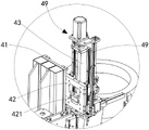
Fig. 1 is a schematic view of the overall structure of a rotary disc type automatic screw locking device provided by the invention.
Fig. 2 is a schematic structural view of a screw locking mechanism of the present embodiment.
Fig. 3 is another angle diagram of the screw locking mechanism according to the present embodiment.
Fig. 4 is a schematic structural diagram of the spring plate conveying mechanism of this embodiment.
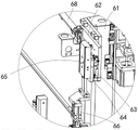
Fig. 5 is a schematic structural diagram of the discharging mechanism in this embodiment.
Fig. 6 is a schematic structural diagram of a pressing mechanism detecting portion in the present embodiment.
Fig. 7 is a schematic view illustrating the profiling suction head of the present embodiment sucking the elastic sheet.
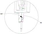
FIG. 8 is a schematic view showing the structure of the copying adsorption head part of the present embodiment.
Detailed Description
To facilitate understanding of the present invention for those skilled in the art, the present invention will be described in further detail with reference to the following detailed description and accompanying drawings.
Referring to fig. 1 to 8, the utility model provides a carousel formula automatic screw locking device for to installing and locking the shell fragment with the screw on the product part, include: the machine table comprises a machine table 1, a turntable conveying mechanism 2 arranged on the machine table and used for bearing and conveying products, a detection pressing mechanism 3 arranged on the machine table and used for detecting and pressing the products, a lock screw mechanism 4 arranged on the machine table and used for locking screws, an elastic sheet conveying mechanism 5 used for conveying elastic sheets to the lock screw mechanism, a discharging mechanism 6 arranged on the machine table and used for discharging the products, and a feeding mechanism 7 arranged on the machine table and used for providing the elastic sheets to the elastic sheet conveying mechanism.
The detection pressing mechanism, the screw locking mechanism and the discharging mechanism are sequentially arranged around the turntable conveying mechanism. The screw locking mechanism 4 comprises a supporting plate 41 arranged on the machine table, a fixed plate 42 arranged at a position of the supporting plate close to the upper end, a movable plate 43 movably connected to the fixed plate, a first vertical guide rail 431 vertically arranged on the front surface of the movable plate, an electric screwdriver fixing seat 44 movably connected with the first vertical guide rail, and an electric screwdriver 45 arranged on the electric screwdriver fixing seat; a profiling adsorption head 46 for adsorbing the elastic sheet is arranged at a position, close to the lower end, of the movable plate, an electric screwdriver hole 461 for allowing a screwdriver head of an electric screwdriver to penetrate is arranged on the profiling adsorption head, the first vertical guide rail is further movably connected with an electric screwdriver traction seat 47, the electric screwdriver traction seat is located above the electric screwdriver fixing seat and is connected with the electric screwdriver fixing seat through a plurality of guide pillars 441, and the electric screwdriver traction seat is driven by a first electric screw 48 arranged on the front face of the movable plate to move along the first vertical guide rail; the elastic sheet conveying mechanism is arranged at the position, close to the lower end, of the supporting plate. In this embodiment, the electric screwdriver in the prior art is adopted, and the electric screwdriver is a mature prior art and will not be described in detail here. The bottom of fly leaf is connected with a connection plate, and the profile modeling adsorption head is fixed in the bottom surface department of connecting the plate through a support. Simultaneously, screw feeder supplies the screw to the screwdriver, for example the screw feeder of air blowing type, in this embodiment, be provided with a feed block of being connected with screw feeder between connecting plate and the support that is used for fixed profile modeling adsorption head, the screwdriver head of screwdriver can insert this feed block, passes and passes the support that is used for fixed profile modeling adsorption head from the feed block behind the absorption screw, and insert the profile modeling hole of profile modeling adsorption head, finally wear out from the lower extreme of profile modeling adsorption head. The shape of the profiling adsorption head is matched with that of the elastic sheet, and the other arm can be opened after one arm of the elastic sheet is pressed, so that the screwdriver head and the screw can be conveniently inserted into the mounting hole in the elastic sheet.
The movable plate 43 is connected to the fixed plate by a second vertical rail 432 vertically provided at the back of the movable plate, and the movable plate moves in the vertical direction by being driven by a second electric screw 49 provided at the back of the movable plate.
The first electric lead screw 48 and the second electric lead screw 49 have the same structure, and each of them includes a lead screw motor 481 disposed on the movable plate, and a screw 482 connected to the rotating shaft of the lead screw motor, and the screw is connected to the movable plate through a screw support 483, in this embodiment, the lead screw motor of the first electric lead screw is disposed on the front surface of the movable plate near the lower end, and the motor of the second electric lead screw is disposed on the top end of the back surface of the movable plate. The fixed plate 42 is provided with a threaded sleeve 421 for connecting the second electric screw, and the threaded sleeve is fixed, so that the whole movable plate can move in the vertical direction when the screw motor drives the screw to rotate.
The elastic sheet conveying mechanism 5 comprises a feeding support 51 arranged on the support plate 41, a feeding plate 52 movably connected on the feeding support, and a feeding suction head 53 arranged on one side of the feeding plate close to the electric screwdriver and used for adsorbing the elastic sheet, wherein the feeding suction head is rotatably connected on the feeding plate. The feed plate 52 is movably attached to the feed stand by a feed rail 54 horizontally disposed on a side facing the feed stand, and the feed plate is moved in a horizontal direction by a feed cylinder 55 disposed on the feed stand. In this embodiment, the feeding cylinder drives the feeding plate to move towards a direction close to or away from the turntable mechanism (i.e. the feeding suction head is moved to the lower part of the electric screwdriver bit, so that the screwdriver bit with the screw passes through a preset screw hole on the elastic sheet, and the elastic sheet is sucked away through the profiling adsorption head). The feeding suction head can automatically rotate for a certain angle (driven by a small stepping motor or a servo motor, not shown in the figure), and avoids interference when the screwdriver head sleeves the screw into the elastic sheet.
A first limiting member 56 and a second limiting member 57 for limiting the moving position of the feeding plate are respectively arranged on two sides of the feeding plate 52, and a first buffer 58 and a second buffer 59 matched with the first limiting member and the second limiting member are arranged on the feeding bracket.
The guide post 441 is sleeved with a spring 442, two ends of the spring are respectively connected with the electric screwdriver fixing seat 44 and the electric screwdriver traction seat 47, and an electric screwdriver limiting block 433 for limiting the moving position of the electric screwdriver traction seat is arranged at the position, corresponding to the electric screwdriver traction seat, of the top of the movable plate 43. The guide pillar is provided with two in this embodiment, and the guide pillar lower extreme is fixed on the electricity is criticized the fixing base, upper end and electricity criticize traction seat movably connected, and the top of guide pillar is provided with the stopper simultaneously.
The discharging mechanism 6 comprises a discharging upright post 61 arranged on the machine table 1, a discharging plate 62 arranged on the discharging upright post, a discharging guide rail 63 horizontally arranged on the discharging plate, a cylinder seat 64 movably connected on the discharging guide rail, a pressing cylinder 65 vertically fixed on the cylinder seat, a clamping jaw cylinder 66 connected with a piston rod of the pressing cylinder and used for clamping a product, and a discharging conveyor belt 67 arranged on the base table and used for conveying the product; the cylinder block moves along the discharge guide rail under the drive of a discharge cylinder 68 arranged on the discharge plate.
The feeding mechanism 7 comprises a feeding seat 71 arranged on the machine table 1, a vibrating disc 72 arranged on the feeding seat, and a material guide channel 73 used for guiding the elastic sheet to the elastic sheet conveying mechanism. The vibrating disk is widely applied to the prior art, and is not described in a redundant way, and the material guide channel is connected with a material outlet of the vibrating disk to guide the elastic sheet to the material supply suction head.
The turntable conveying mechanism 2 comprises a cam divider 21 arranged on the machine table 1, a turntable 22 connected with the cam divider, and a plurality of jigs 23 arranged on the turntable and used for placing products, wherein the jigs are uniformly distributed around the center of the turntable; the machine table is also provided with a turntable motor 24 for driving the cam divider. Be provided with four tools in this embodiment, encircle carousel center evenly distributed. The turntable rotates 90 ° each time.
The detection pressing mechanism 3 comprises a stand column 31 arranged on the base platform, a pressing plate 32 arranged on the stand column, a sensor 33 (a photoelectric sensor is adopted in the embodiment, a visual sensor, a distance sensor and the like are also adopted, and the main detection jig is mainly used for detecting whether products are placed or not) arranged on the pressing plate, a pressing cylinder 34 vertically arranged on the pressing plate, and a pressing block 35 connected with a piston rod of the pressing cylinder and used for pressing the products. This embodiment is provided with two stands, and the pressure strip both ends are connected respectively at two stand tops.
Carousel conveying mechanism 2 encircles and is provided with four stations, and the position that the definition detected hold-down mechanism 3 place is the second station, and the position at lock screw mechanism 4 place is the third station, and the position at discharge mechanism 6 place is the fourth station, and the position relative with lock screw mechanism is for supplying the first station of product material loading, is provided with the grating 11 that is used for safety protection in the position department that platform 1 corresponds first station, still be provided with both hands switch 12 on the board of first station department.
In this embodiment, the part that contacts with each guide rail all is connected with the guide rail that corresponds through the slider, and the quantity of guide rail and slider can set up according to specific demands. When the device is in operation, the loading mechanism provides the elastic sheet for the elastic sheet conveying mechanism, a manual or loading manipulator places a product on the jig, then the switch is pressed down by two hands, the turntable rotates 90 degrees, the sensor of the pressing mechanism detects whether the product exists or not, if the product exists, the pressing cylinder is started (if the product does not exist, a signal is sent, the jig is skipped by subsequent operation), the product is pressed and fixed, and then the turntable rotates 90 degrees. The screw feeder that sets up in addition sends the screw to the confession stub bar department of electricity batch below, and the electricity batch moves down under the drive of second electric lead screw and passes confession stub bar absorption screw (magnetic force adsorbs). The feed cylinder of shell fragment conveying mechanism drives the feed board and removes, and the feed suction head that adsorbs to have the shell fragment removes the below of criticizing the head, and the electricity is criticized and is moved down under the electronic lead screw drive of second this moment, penetrates the screw in the shell fragment screw hole of predetermineeing, and the feed suction head loosens the shell fragment, and the first shell fragment of having inhaled of profile modeling is simultaneously adsorbed, and feed mechanism resets afterwards. And then the first electric screw rod and the second electric screw rod are started, the movable plate moves downwards, the electric screwdriver also moves downwards, the screw is inserted into the threaded hole of the product and locked, the elastic sheet is locked and fixed on the product, and then the screw locking mechanism resets. The turntable continues to rotate 90 degrees, a pressing cylinder (the initial position is positioned above a jig of the turntable) of the discharging mechanism drives the clamping jaw cylinder to move downwards to clamp a product, a piston rod of the discharging cylinder retracts to turn over the product onto the conveyor belt to be sent out, a processing cycle is completed, and the operation is repeated to continue to the next processing cycle. The conveyor belt may be connected to other processes. The screwdriver has a torque feedback function, whether the screw is locked on a product or not can be judged according to the feedback of the torque, and the industrial personal computer gives an alarm through the buzzer to remind a worker when the screw is not locked.
The invention is provided with the screw locking mechanism, the elastic sheet conveying mechanism and the discharging mechanism, the elastic sheet can be automatically locked on a product by screws, the elastic sheet conveying mechanism can convey the elastic sheet to the position below the screwdriver of the screw locking mechanism, the screw locking mechanism can conveniently and quickly take the elastic sheet, simultaneously when the screw locking mechanism takes the elastic sheet, the screwdriver head of the screwdriver drives the screws to penetrate into the preset screw holes of the elastic sheet, the profiling adsorption head can prop open the interference part of the elastic sheet and adsorb the elastic sheet, and the elastic sheet is quickly locked and fixed on the product.
In the description of the present invention, it is to be understood that the indicated orientations or positional relationships are based on the orientations or positional relationships shown in the drawings and are only for convenience in describing the present invention and simplifying the description, but are not intended to indicate or imply that the indicated devices or elements must have a particular orientation, be constructed and operated in a particular orientation, and are not to be construed as limiting the present invention.
In the description of the present invention, "plurality" or "a plurality" means two or more unless specifically defined otherwise.
In the present invention, unless otherwise expressly stated or limited, the terms "connected," "secured," and the like are to be construed broadly, e.g., as meaning permanently attached, removably attached, or integral to one another; can be mechanically or electrically connected; either directly or indirectly through intervening media, either internally or in any other relationship. The specific meanings of the above terms in the present invention can be understood by those skilled in the art according to specific situations.
While the invention has been described in conjunction with the specific embodiments set forth above, it is evident that many alternatives, modifications, and variations will be apparent to those skilled in the art in light of the foregoing description. Accordingly, it is intended to embrace all such alternatives, modifications, and variations that fall within the scope of the included claims.
Claims (10)
1. The utility model provides a carousel formula automatic screw locking device for to installing and locking the shell fragment with the screw on the product part, its characterized in that includes:
a machine table (1);
a turntable conveying mechanism (2) arranged on the machine table and used for bearing and conveying products;
a detection pressing mechanism (3) which is arranged on the machine table and is used for detecting and pressing the product;
a screw locking mechanism (4) arranged on the machine table and used for locking screws;
the spring plate conveying mechanism (5) is used for conveying the spring plates to the screw locking mechanism;
a discharging mechanism (6) arranged on the machine table and used for discharging the product;
the feeding mechanism (7) is arranged on the machine table and used for providing the elastic sheets for the elastic sheet conveying mechanism;
the detection pressing mechanism, the screw locking mechanism and the discharging mechanism are sequentially arranged around the turntable conveying mechanism; the screw locking mechanism (4) comprises a supporting plate (41) arranged on the machine table, a fixed plate (42) arranged at the position, close to the upper end, of the supporting plate, a movable plate (43) movably connected to the fixed plate, a first vertical guide rail (431) vertically arranged on the front face of the movable plate, an electric screwdriver fixing seat (44) movably connected with the first vertical guide rail, and an electric screwdriver (45) arranged on the electric screwdriver fixing seat; a profiling adsorption head (46) for adsorbing the elastic sheet is arranged at the position, close to the lower end, of the movable plate, and an electric screwdriver hole (461) through which a screwdriver head of the electric screwdriver passes is arranged on the profiling adsorption head; the first vertical guide rail is also movably connected with an electric screwdriver traction seat (47), the electric screwdriver traction seat is positioned above the electric screwdriver fixing seat and is connected with the electric screwdriver fixing seat through a plurality of guide pillars (441), and the electric screwdriver traction seat is driven by a first electric lead screw (48) arranged on the front surface of the movable plate to move along the first vertical guide rail; the elastic sheet conveying mechanism is arranged at the position, close to the lower end, of the supporting plate.
2. The rotary disc type automatic screw locking device is characterized in that the elastic sheet conveying mechanism (5) comprises a feeding support (51) arranged on a support plate (41), a feeding plate (52) movably connected to the feeding support, a feeding suction head (53) arranged on one side of the feeding plate close to the electric screwdriver and used for sucking the elastic sheet, and the feeding suction head is rotatably connected to the feeding plate; the feeding plate (52) is movably connected to the feeding support through a feeding guide rail (54) horizontally arranged on one side facing the feeding support, and the feeding plate is driven by a feeding cylinder (55) arranged on the feeding support to move along the horizontal direction.
3. The rotary disk type automatic screw locking device as claimed in claim 2, wherein a first limiting member (56) and a second limiting member (57) for limiting the moving position of the feeding plate are respectively arranged on both sides of the feeding plate (52), and a first buffer (58) and a second buffer (59) matched with the first limiting member and the second limiting member are arranged on the feeding bracket.
4. The rotary disc type automatic screw locking device as claimed in claim 1, wherein the movable plate (43) is connected with the fixed plate through a second vertical guide rail (432) vertically arranged at the back of the movable plate, and the movable plate moves in the vertical direction driven by a second electric lead screw (49) arranged at the back of the movable plate; the first electric lead screw (48) and the second electric lead screw (49) are the same in structure and respectively comprise a lead screw motor (481) arranged on the movable plate and a screw rod (482) connected with the lead screw motor in a rotating shaft mode, and the screw rods are connected with the movable plate through screw rod supporting pieces (483); the fixing plate (42) is provided with a threaded sleeve (421) used for connecting a second electric lead screw.
5. The rotary disc type automatic screw locking device as claimed in claim 1, wherein the feeding mechanism (7) comprises a feeding seat (71) arranged on the machine table (1), a vibrating disc (72) arranged on the feeding seat, and a material guiding channel (73) for guiding the shrapnel to the shrapnel conveying mechanism.
6. The rotary disc type automatic screw locking device as claimed in claim 1, wherein the guide post (441) is sleeved with a spring (442), two ends of the spring are respectively connected with the electric screwdriver fixing seat (44) and the electric screwdriver traction seat (47), and an electric screwdriver limiting block (433) for limiting the moving position of the electric screwdriver traction seat is arranged at a position corresponding to the electric screwdriver traction seat on the top of the movable plate (43).
7. The rotating disc type automatic screw locking device as claimed in claim 1, wherein the discharging mechanism (6) comprises a discharging upright post (61) arranged on the machine table (1), a discharging plate (62) arranged on the discharging upright post, a discharging guide rail (63) horizontally arranged on the discharging plate, a cylinder seat (64) movably connected to the discharging guide rail, a pressing cylinder (65) vertically fixed on the cylinder seat, a clamping jaw cylinder (66) connected with a piston rod of the pressing cylinder and used for clamping a product, and a discharging conveyor belt (67) arranged on the machine table and used for conveying the product; the cylinder block moves along the discharging guide rail under the driving of a discharging cylinder (68) arranged on the discharging plate.
8. The rotary disc type automatic screw locking device is characterized in that the rotary disc conveying mechanism (2) comprises a cam divider (21) arranged on the machine table (1), a rotary disc (22) connected with the cam divider, and a plurality of jigs (23) arranged on the rotary disc and used for placing products, wherein the jigs are uniformly distributed around the center of the rotary disc; the machine table is also provided with a turntable motor (24) for driving the cam divider.
9. The rotating disc type automatic screw locking device as claimed in claim 1, wherein the detection pressing mechanism (3) comprises a column (31) arranged on the base, a pressing plate (32) arranged on the column, a sensor (33) arranged on the pressing plate and used for detecting the product, a pressing cylinder (34) vertically arranged on the pressing plate, and a pressing block (35) connected with a piston rod of the pressing cylinder and used for pressing the product.
10. The automatic screw locking device of carousel formula of claim 1, characterized in that carousel conveying mechanism (2) encircles and is provided with four stations, and the definition detects that the position that hold-down mechanism (3) is located is the second station, and the position that lock screw mechanism (4) is located is the third station, and the position that discharge mechanism (6) is located is the fourth station, and the position relative with lock screw mechanism is the first station that supplies the product material loading, is provided with grating (11) that are used for safety protection in the position department that board (1) corresponds first station, still be provided with both hands switch (12) on the board of first station department.
Priority Applications (1)
| Application Number | Priority Date | Filing Date | Title |
|---|---|---|---|
| CN201921151967.4U CN210615721U (en) | 2019-07-22 | 2019-07-22 | Rotary disc type automatic screw locking device |
Applications Claiming Priority (1)
| Application Number | Priority Date | Filing Date | Title |
|---|---|---|---|
| CN201921151967.4U CN210615721U (en) | 2019-07-22 | 2019-07-22 | Rotary disc type automatic screw locking device |
Publications (1)
| Publication Number | Publication Date |
|---|---|
| CN210615721U true CN210615721U (en) | 2020-05-26 |
Family
ID=70745872
Family Applications (1)
| Application Number | Title | Priority Date | Filing Date |
|---|---|---|---|
| CN201921151967.4U Active CN210615721U (en) | 2019-07-22 | 2019-07-22 | Rotary disc type automatic screw locking device |
Country Status (1)
| Country | Link |
|---|---|
| CN (1) | CN210615721U (en) |
Cited By (1)
| Publication number | Priority date | Publication date | Assignee | Title |
|---|---|---|---|---|
| CN110181279A (en) * | 2019-07-22 | 2019-08-30 | 惠州市维尔康精密部件有限公司 | A kind of rotating disc type automatic lock screw device |
-
2019
- 2019-07-22 CN CN201921151967.4U patent/CN210615721U/en active Active
Cited By (1)
| Publication number | Priority date | Publication date | Assignee | Title |
|---|---|---|---|---|
| CN110181279A (en) * | 2019-07-22 | 2019-08-30 | 惠州市维尔康精密部件有限公司 | A kind of rotating disc type automatic lock screw device |
Similar Documents
| Publication | Publication Date | Title |
|---|---|---|
| CN106826173B (en) | Full-automatic modularized assembly system | |
| CN106391926B (en) | A kind of electronic component pin molding machine | |
| CN112276550B (en) | Assembly equipment for conductive PAD | |
| CN111069902A (en) | Automatic man-machine combination assembling line for mainboard controller | |
| CN210615721U (en) | Rotary disc type automatic screw locking device | |
| CN112496712A (en) | Full-automatic bag and hook assembling machine | |
| CN110181279A (en) | A kind of rotating disc type automatic lock screw device | |
| CN110153697A (en) | Button switch automatic assembling apparatus and its assembly method | |
| CN213857974U (en) | Remote controller shell assembling device | |
| CN113458749A (en) | Automatic assembly production line for touch screen | |
| CN205723238U (en) | Limit switch head kludge | |
| CN217800110U (en) | Screw locking machine for automatic screw locking process | |
| CN109202444B (en) | Assembly equipment of cylinder dabber | |
| CN110809396A (en) | Automatic production line of circuit board | |
| CN215358509U (en) | Equipment for producing ceiling nail | |
| CN206982130U (en) | A kind of bolt and nut full automatic assembly machine | |
| CN115464364A (en) | Automatic assembling equipment for stepping motor | |
| CN215830901U (en) | Automatic assembly production line for touch screen | |
| CN113909354A (en) | Elastic sheet bending equipment and bending method | |
| CN210209367U (en) | Full-automatic buzzer assembling machine | |
| CN210959328U (en) | Automatic production line of circuit board | |
| CN114700321A (en) | Intelligent automatic all-in-one machine for 5G and new energy automobile inductance paint stripping and bending forming | |
| CN210997407U (en) | Holding device for rivet screw assembling machine | |
| CN112810887A (en) | Automatic cover net equipment of fastener | |
| CN216802374U (en) | Automated device for covering a module box |
Legal Events
| Date | Code | Title | Description |
|---|---|---|---|
| GR01 | Patent grant | ||
| GR01 | Patent grant |