CN210126082U - Automatic change structure is got to clamp of device - Google Patents
Automatic change structure is got to clamp of device Download PDFInfo
- Publication number
- CN210126082U CN210126082U CN201921056461.5U CN201921056461U CN210126082U CN 210126082 U CN210126082 U CN 210126082U CN 201921056461 U CN201921056461 U CN 201921056461U CN 210126082 U CN210126082 U CN 210126082U
- Authority
- CN
- China
- Prior art keywords
- push
- pull
- moving
- groove
- mounting
- Prior art date
- Legal status (The legal status is an assumption and is not a legal conclusion. Google has not performed a legal analysis and makes no representation as to the accuracy of the status listed.)
- Active
Links
Images


Abstract
The utility model discloses an automatic change structure is got to device's clamp, the mounting panel comprises a mounting panel, the top side fixed mounting of mounting panel has the regulating box, the bottom side of regulating box is the opening setting, two removal holes have been seted up to the bottom side of mounting panel, remove downthehole movable mounting and have the carriage release lever, the both ends of carriage release lever all extend to outside removing the hole, the push-and-pull rod is all rotated and installed to the bottom of two carriage release levers, one side that two carriage release levers are close to each other is equipped with two splint of movable mounting on the mounting panel bottom side, the bottom of two push-and-pull rods is rotated respectively and is installed on one side that two splint kept away from. The utility model discloses simple structure, motor drive movable plate remove, and then drive splint and mechanical through the carriage release lever and grab each other and be close to, with the work piece centre gripping, the rotation range of control motor and axis of rotation can control the distance that splint and machinery grabbed, can press from both sides the work piece of getting equidimension not, has satisfied the user demand.
Description
Technical Field
The utility model relates to an automatic technical field especially relates to an automatic change clamp of device and get structure.
Background
The clamp is a device used for fixing a processing object to enable the processing object to occupy a correct position in the mechanical manufacturing process so as to accept construction or detection, a clamping device used in the current market is generally provided with a single clamp, only can clamp objects within a certain length and diameter range, if the length of the object is too long, two separated clamping devices are required to be started simultaneously, but synchronous operation of the two separated clamping devices cannot be guaranteed, the objects are easily damaged due to torque force in the clamping process, and therefore an automatic clamping device is provided for solving the problems.
The patent that publication is CN207258722U discloses an automatic change clamp and get device, including fixing base and control module, fixing base one end is equipped with the feeding seat, and the middle part of fixing base is equipped with the supporting seat, be equipped with on the feeding seat and put the silo, through drawing the flitch intercommunication between the discharge end of feeding seat and last process, draw flitch one end and last process discharge end intercommunication, this utility model discloses can effectively link up every process and conveyer belt, practiced thrift a large amount of manpowers, effectively improved the efficiency of production, but this automatic mechanical of getting the device of pressing from both sides is grabbed fixedly and is set up, only can adapt to the work piece of fixed size, consequently can not satisfy the user demand, has the improvement space.
SUMMERY OF THE UTILITY MODEL
The utility model aims at solving the defects existing in the prior art, and providing an automatic clamping device.
In order to achieve the above purpose, the utility model adopts the following technical scheme:
a clamping structure of an automatic device comprises a mounting plate, wherein an adjusting box is fixedly mounted on the top side of the mounting plate, the bottom side of the adjusting box is provided with an opening, two moving holes are formed in the bottom side of the mounting plate, moving rods are movably mounted in the moving holes, two ends of each moving rod extend out of the moving holes, push-pull rods are rotatably mounted at the bottom ends of the two moving rods, two clamping plates movably mounted on the bottom side of the mounting plate are arranged on one sides, close to each other, of the two moving rods, the bottom ends of the two push-pull rods are rotatably mounted on one sides, far away from each other, of the two clamping plates respectively, mechanical grippers are fixedly mounted at the bottom sides of the two clamping plates, cushion pads are fixedly mounted at one sides, close to each other, of the two moving rods are fixedly mounted at the top ends of the two moving rods, the utility model discloses a push-and-pull adjusting box, including adjusting box, push-and-pull strip, push-and-pull groove, push-and-pull inslot movable mounting has the push-and-pull piece, push-and-pull piece and push-and-pull piece, the one end fixed mounting that push-and-pull piece was kept away from to L type pole is on the one end that the axis of rotation is close to push-and-pull piece.
Preferably, the top side of the mounting plate is provided with a moving groove between the two moving rods, a limiting rod is movably mounted in the moving groove, and the top end of the limiting rod extends into the adjusting box and is fixedly mounted on the bottom side of the moving plate.
Preferably, the limiting grooves are formed in the inner walls of the two sides of the moving groove, the same limiting block is slidably mounted in the two limiting grooves, and the bottom end of the limiting rod is fixedly mounted on the top side of the limiting block.
Preferably, the bottom side of mounting panel has seted up the sliding tray, and the top side of two splint is all slidable mounting in the sliding tray.
Preferably, a motor is fixedly mounted on one side of the adjusting box, and one end, far away from the push-pull strip, of the rotating shaft is fixedly mounted on an output shaft of the motor through a coupler.
Preferably, a rotating groove is formed in one side, close to the rotating shaft, of the push-pull block, and one end, far away from the rotating shaft, of the L-shaped rod is rotatably installed in the rotating groove.
Compared with the prior art, the beneficial effects of the utility model are that:
in the utility model, the motor is started through the matching use of the movable plate, the rotating hole, the rotating shaft, the motor, the fixed rod, the push-pull strip, the push-pull groove, the push-pull block, the rotating groove and the L-shaped rod, the rotating shaft drives the L-shaped rod to rotate, the L-shaped rod drives the push-pull block to move in the push-pull groove and drives the push-pull strip to move up and down in the adjusting box, the push-pull rod drives the fixed rod to move, and then the movable plate is driven to move, the two movable rods are driven by the movable plate to respectively move up and down in the two movable holes on the mounting plate through the matching use of the mounting plate, the adjusting box, the movable holes, the movable rods, the clamping plate, the push-pull rod, the mechanical claw, the buffer cushion, the movable plate, the movable groove, the limiting block and the limiting rod, when the movable rods move downwards, the movable rods push the push-pull rod, the two clamping plates are further pushed to approach each other, and the two clamping plates respectively drive the two mechanical grippers to approach each other so as to clamp the workpiece;
the utility model discloses simple structure, motor drive movable plate remove, and then drive splint and mechanical through the carriage release lever and grab each other and be close to, with the work piece centre gripping, the rotation range of control motor and axis of rotation can control the distance that splint and machinery grabbed, can press from both sides the work piece of getting equidimension not, has satisfied the user demand.
Drawings
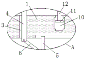
Fig. 1 is a schematic structural diagram of a clamping structure of an automatic device according to the present invention;
fig. 2 is a schematic structural diagram of a portion a in a clamping structure diagram 1 of an automatic device according to the present invention;
fig. 3 is a schematic structural diagram of a part B in the structure diagram 1 of a clamping structure of an automatic device according to the present invention;
fig. 4 is a schematic structural view of a structure pushing-pulling strip for clamping of an automatic device according to the present invention.
In the figure: the device comprises a mounting plate 1, an adjusting box 2, a moving hole 3, a moving rod 4, a clamping plate 5, a push-pull rod 6, a mechanical claw 7, a cushion pad 8, a moving plate 9, a moving groove 10, a limiting block 11, a limiting rod 12, a rotating hole 13, a rotating shaft 14, a motor 15, a fixed rod 16, a push-pull strip 17, a push-pull groove 18, a push-pull block 19, a rotating groove 20 and a 21L-shaped rod.
Detailed Description
The technical solutions in the embodiments of the present invention will be described clearly and completely with reference to the accompanying drawings in the embodiments of the present invention, and it is obvious that the described embodiments are only some embodiments of the present invention, not all embodiments.
Referring to fig. 1-4, an automatic device clamping structure comprises a mounting plate 1, a regulating box 2 is fixedly mounted on the top side of the mounting plate 1, the bottom side of the regulating box 2 is provided with an opening, two moving holes 3 are formed in the bottom side of the mounting plate 1, moving rods 4 are movably mounted in the moving holes 3, two ends of each moving rod 4 extend out of the moving holes 3, push-pull rods 6 are rotatably mounted at the bottom ends of the two moving rods 4, two clamping plates 5 movably mounted on the bottom side of the mounting plate 1 are arranged on one sides of the two moving rods 4 close to each other, the bottom ends of the two push-pull rods 6 are rotatably mounted on one sides of the two clamping plates 5 away from each other, mechanical grippers 7 are fixedly mounted at the bottom sides of the two clamping plates 5, cushion pads 8 are fixedly mounted at one sides of the two mechanical grippers 7 close to each other, and a moving plate 9 located in the regulating, a fixed rod 16 is fixedly installed on the top side of the moving plate 9, a push-pull strip 17 is fixedly installed at the top end of the fixed rod 16, a rotating hole 13 is formed in the inner wall of one side of the adjusting box 2, a rotating shaft 14 is rotatably installed in the rotating hole 13, both ends of the rotating shaft 14 extend out of the rotating hole 13, a push-pull groove 18 is formed in one side, close to the rotating shaft 14, of the push-pull strip 17, a push-pull block 19 is movably installed in the push-pull groove 18, one side of the push-pull block 19 extends out of the push-pull groove 18 and is rotatably installed with an L-shaped rod 21, one end, far away from the push-pull strip 17, of the L-shaped rod 21 is fixedly installed at one end, close to the push-pull strip 17, of the rotating shaft 14 is driven by a motor 15 to rotate in the rotating hole 13, the rotating shaft 14 drives the L-shaped rod 21 to rotate, and then the moving plate 9 is driven to move, and the moving plate 9 drives the two moving rods 4 to respectively move up and down in the two moving holes 3 on the mounting plate 1.
The top side of the mounting plate 1 is provided with a moving groove 10 positioned between the two moving rods 4, a limiting rod 12 is movably mounted in the moving groove 10, the top end of the limiting rod 12 extends into the adjusting box 2 and is fixedly mounted on the bottom side of the moving plate 9, the inner walls of the two sides of the moving groove 10 are respectively provided with a limiting groove, the two limiting grooves are internally and slidably mounted with the same limiting block 11, the bottom end of the limiting rod 12 is fixedly mounted on the top side of the limiting block 11, the bottom side of the mounting plate 1 is provided with a sliding groove, the top sides of the two clamping plates 5 are respectively and slidably mounted in the sliding grooves, one side of the adjusting box 2 is fixedly mounted with a motor 15, one end of the rotating shaft 14 far away from the push-pull strip 17 is fixedly mounted on an output shaft of the motor 15 through a coupler, one side of the push-pull block 19 close to the rotating shaft 14 is, the movable rod 4 pushes the push-pull rod 6, and then pushes two clamp plates 5 to be close to each other, the two clamp plates 5 respectively drive two mechanical grippers 7 to be close to each other, the workpiece is clamped, the arrangement of the cushion pads 8 enables the clamping mechanism to clamp the workpiece without damaging the workpiece due to over-tight clamping, when the movable rod 4 moves upwards, the movable rod 4 drives the two mechanical grippers 7 to be away from each other through the push-pull rod 6, the workpiece is put down, the distance between the clamp plates 5 and the mechanical grippers 7 can be controlled through the rotation range of the control motor 15 and the rotation shaft 14, and the workpieces with different sizes can be clamped.
The working principle is as follows: the motor 15 is started to drive the rotating shaft 14 to rotate in the rotating hole 13, the rotating shaft 14 drives the L-shaped rod 21 to rotate, the L-shaped rod 21 drives the push-pull block 19 to move in the push-pull groove 18 and drives the push-pull strip 17 to move up and down in the adjusting box 2, the push-pull rod 17 drives the fixed rod 16 to move and further drives the movable plate 9 to move, the movable plate 9 drives the two movable rods 4 to move up and down in the two movable holes 3 on the mounting plate 1 respectively, when the movable rod 4 moves downwards, the movable rod 4 pushes the push-pull rod 6 and further pushes the two clamping plates 5 to approach each other, the two clamping plates 5 drive the two mechanical grippers 7 to approach each other respectively to clamp a workpiece, and the cushion pad 8 is arranged to ensure that the clamping mechanism does not clamp the workpiece too tightly to damage the workpiece when clamping the workpiece, when the movable rod 4 moves upwards, the movable rod 4, therefore, the workpiece is put down, the distance between the clamping plate 5 and the mechanical claw 7 can be controlled by controlling the rotation amplitude of the motor 15 and the rotating shaft 14, workpieces with different sizes can be clamped, and the use requirement is met.
The above, only be the concrete implementation of the preferred embodiment of the present invention, but the protection scope of the present invention is not limited thereto, and any person skilled in the art is in the technical scope of the present invention, according to the technical solution of the present invention and the utility model, the concept of which is equivalent to replace or change, should be covered within the protection scope of the present invention.
Claims (6)
1. The clamping structure of the automatic device comprises a mounting plate (1) and is characterized in that an adjusting box (2) is fixedly mounted on the top side of the mounting plate (1), the bottom side of the adjusting box (2) is provided with an opening, two moving holes (3) are formed in the bottom side of the mounting plate (1), moving rods (4) are movably mounted in the moving holes (3), two ends of each moving rod (4) extend out of the moving holes (3), push-pull rods (6) are rotatably mounted at the bottom ends of the two moving rods (4), two clamping plates (5) movably mounted on the bottom side of the mounting plate (1) are arranged on the sides, close to each other, of the two moving rods (4), the bottom ends of the two push-pull rods (6) are rotatably mounted on the sides, far away from each other, of the two clamping plates (5) are fixedly mounted with mechanical grippers (7), cushion pads (8) are fixedly mounted on the sides, close to each other, of the two mechanical, the top ends of the two moving rods (4) are fixedly provided with the same moving plate (9) positioned in the adjusting box (2), the top side of the moving plate (9) is fixedly provided with a fixed rod (16), the top end of the fixed rod (16) is fixedly provided with a push-pull strip (17), the utility model discloses a push-pull mechanism of a motor vehicle, including regulating box (2), rotating hole (13) has been seted up on the one side inner wall of regulating box (2), rotating shaft (14) have been installed to rotating hole (13) internal rotation, the both ends of rotating shaft (14) all extend to outside rotating hole (13), push-pull groove (18) have been seted up to one side that push-pull strip (17) are close to rotating shaft (14), movable mounting has push-pull piece (19) in push-pull groove (18), one side of push-pull piece (19) extends to push-pull groove (18) and outer and rotation-mounting has L type pole (21), the one end fixed mounting that push-pull strip (17) was kept away from in L type pole (21) is.
2. The automatic device clamping structure as claimed in claim 1, wherein a moving groove (10) between the two moving rods (4) is formed in the top side of the mounting plate (1), a limiting rod (12) is movably mounted in the moving groove (10), and the top end of the limiting rod (12) extends into the adjusting box (2) and is fixedly mounted on the bottom side of the moving plate (9).
3. The automatic change device press from both sides get structure according to claim 2, characterized in that, the both sides inner wall of shifting chute (10) has all seted up the spacing groove, and slidable mounting has same stopper (11) in two spacing grooves, and the bottom fixed mounting of gag lever post (12) is on the top side of stopper (11).
4. The automatic clamping device as claimed in claim 1, wherein the bottom side of the mounting plate (1) is provided with a sliding groove, and the top sides of the two clamping plates (5) are slidably mounted in the sliding groove.
5. The gripping structure of an automated device according to claim 1, wherein a motor (15) is fixedly mounted on one side of the adjusting box (2), and one end of the rotating shaft (14) far away from the push-pull strip (17) is fixedly mounted on an output shaft of the motor (15) through a coupling.
6. The automatic clamping device as claimed in claim 1, wherein a rotating groove (20) is formed in one side of the push-pull block (19) close to the rotating shaft (14), and one end of the L-shaped rod (21) far away from the rotating shaft (14) is rotatably installed in the rotating groove (20).
Priority Applications (1)
| Application Number | Priority Date | Filing Date | Title |
|---|---|---|---|
| CN201921056461.5U CN210126082U (en) | 2019-07-08 | 2019-07-08 | Automatic change structure is got to clamp of device |
Applications Claiming Priority (1)
| Application Number | Priority Date | Filing Date | Title |
|---|---|---|---|
| CN201921056461.5U CN210126082U (en) | 2019-07-08 | 2019-07-08 | Automatic change structure is got to clamp of device |
Publications (1)
| Publication Number | Publication Date |
|---|---|
| CN210126082U true CN210126082U (en) | 2020-03-06 |
Family
ID=69664870
Family Applications (1)
| Application Number | Title | Priority Date | Filing Date |
|---|---|---|---|
| CN201921056461.5U Active CN210126082U (en) | 2019-07-08 | 2019-07-08 | Automatic change structure is got to clamp of device |
Country Status (1)
| Country | Link |
|---|---|
| CN (1) | CN210126082U (en) |
Cited By (1)
| Publication number | Priority date | Publication date | Assignee | Title |
|---|---|---|---|---|
| CN112498841A (en) * | 2020-12-07 | 2021-03-16 | 贵州精博高科科技有限公司 | Fuse-link anterior segment that location effect is good auxiliary fixtures for automatic assembly line |
-
2019
- 2019-07-08 CN CN201921056461.5U patent/CN210126082U/en active Active
Cited By (1)
| Publication number | Priority date | Publication date | Assignee | Title |
|---|---|---|---|---|
| CN112498841A (en) * | 2020-12-07 | 2021-03-16 | 贵州精博高科科技有限公司 | Fuse-link anterior segment that location effect is good auxiliary fixtures for automatic assembly line |
Similar Documents
| Publication | Publication Date | Title |
|---|---|---|
| WO2022021959A1 (en) | Multi-station fixing, clamping and automatic stamping apparatus based on multi-axis industrial robot | |
| CN105129418B (en) | A kind of feeding double-purpose clamping jaw | |
| CN105437451A (en) | Full-automatic injection molding production line of data wire ports | |
| CN109941765B (en) | Multipurpose feeding device and feeding method | |
| CN205086018U (en) | Full -automatic board separator | |
| CN102001030B (en) | Automatic material feeding/taking manipulator of double end surface grinding machine | |
| CN213444657U (en) | Automatic feeding device | |
| CN210126082U (en) | Automatic change structure is got to clamp of device | |
| CN110356156B (en) | Translation formula license plate printing device | |
| CN216638060U (en) | Clamping device | |
| CN105460603A (en) | Loading and unloading device of numerical control lathe for machining flange end plate | |
| CN104708303B (en) | Carry at a high speed the high speed method for carrying of module | |
| CN210635406U (en) | Loading attachment of multipurpose | |
| CN110586729B (en) | Automatic stamping device of complicated stamping workpiece of major axis class | |
| CN216575901U (en) | Sand casting deburring device | |
| CN107324052B (en) | Pole piece feeding device | |
| CN201655774U (en) | Feeding device of marking machine | |
| CN210436141U (en) | Automatic grabbing device | |
| CN210630176U (en) | Chuck mechanism for component inserter | |
| CN218776464U (en) | Clamp with limiting and combining functions | |
| CN208276659U (en) | A kind of handle automatic polishing equipment | |
| CN210335955U (en) | Automatic change robot hand sign indicating number aluminium ingot device | |
| CN211444125U (en) | Double-end automatic feed manipulator | |
| CN212738683U (en) | Circulation device for processing diffusion plate | |
| CN218706960U (en) | Grabbing device is used in cutting die production |
Legal Events
| Date | Code | Title | Description |
|---|---|---|---|
| GR01 | Patent grant | ||
| GR01 | Patent grant |